1
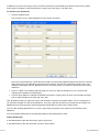
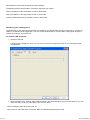
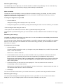
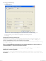
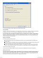
1 of 10
Maintaining your controller settings
Your Saitek X52 Pro Flight Control System (FCS) is supplied ready for use. However, we want you to use it in the
way that suits you best. We've therefore included the facility for you to change various settings on your stick and
throttle units. You can, for example, vary the brightness of the LED buttons, check your stick is working correctly or
change the way the date is displayed on your Multi-Functional Display (MFD).
You change your controller settings in the Saitek X52 Pro Flight Stick properties window. There are two ways you
can open this window. Either:
Double-click on the Game Controllers icon in the Control Panel and then click Properties in the Game
Controllers window that is displayed. Or,
If the SST programming software has been installed, right-click on the Saitek X52 Pro Flight Stick profiler
icon in your task bar and select Control Panel from the popup list of options displayed.
The Saitek X52 Pro Flight Stick properties window consists of five separate tabs. You can view and change
various controller settings in each tab. The settings you can change are described in the following sections.
Testing your controller
You can make sure that the various features of your controller are working correctly. You do this in the Test tab of
the Saitek X52 Pro Flight Stick properties window.
To test your controllers, follow the steps below:
1. Click the Test tab.
The controller features that you can test are displayed right.
2. Test each feature as required.
20/12/2006 08:47
2 of 10
The way you do this varies, depending on what the feature does. It may, for example, involve pressing the
corresponding button, or turning the corresponding rotary control.
The features you can test are explained in the following sections.
Testing axes
You can test the following axes and controls:
Feature Explanation
X/Y Axes Move the flight stick backwards and forwards or from left to right. The + symbol moves in the X/Y Axes
box, to show the drivers are picking up the stick movement correctly.
Twist The vertical gray line represents the center point of the flight stick. Rotate the flight stick clockwise or
anti-clockwise. This is the rudder that enables you to change direction outside the X and Y axes. If the drivers are
detecting the movement correctly a red band is displayed on either side of the center point line.
Throttle Move the throttle up or down to increase or decrease your acceleration. A red band shows the current rate
of acceleration, ranging from 0% (no red) to the maximum acceleration at 100% (the box is filled with red).
Rotary 1 and 2 Rotate the rotary controls on the throttle unit. These are user-defined via the SST programming
software or within each game. They range from 0% (no red) to 100% (the box is filled with red). You may, for
example, use them to control fuel mixture or radar gain.
Precision Slide Move the slide control on the throttle unit. This is user-defined via the SST programming software
or within each game, and ranges from 0% (no red) to 100% (the box is filled with red). You may, for example, use it
to control pitch or fuel mixture.
Testing buttons, toggle and mode switches
You can make sure button presses are being detected by the drivers. Press each button on your flight stick or
throttle unit that you want to test, in turn. The corresponding numbered disc lights up in the Buttons panel of the
Test tab.
Note: What each button does depends on the game in progress. You can, if you wish, assign functions to individual
buttons using the SST programming software. See the SST programming software manual for details.
The numbered boxes in the Toggle Switches panel illuminate when you press the toggle switches on your flight
stick unit.
The three red boxes in the Mode panel indicate which mode is currently selected. The top box represents mode 1,
the middle box mode 2 and the lower box mode 3. Make sure your mode selector switch is working correctly by
rotating the switch to change modes. The corresponding box in the Mode panel illuminates.
Testing POVs
Moving the POV controls on your flight stick in the various directions should illuminate the corresponding direction
arrows in the POV panel. POV 1 is used to look around the cockpit. POV 2 can be configured to trigger four or
eight different functions of your choice. See the SST programming software manual for details.
You can also make sure that movements of the Throttle Hat control cause the corresponding direction arrows in
the POV panel to illuminate. As for POV 2, the throttle hat control can be configured to trigger four or eight different
functions of your choice.
Testing the ministick
The ministick on the throttle unit is used to perform actions you would otherwise use your mouse for. Moving the
ministick moves the + symbol in the Mouse X/Mouse Y box.
Maintaining deadzones
You can create deadzones for each range and axis your controller features move in. They reduce interference that
may be caused by unintended movements of the flight stick and other controls. For example, you may want to
move your stick in the X axis only, but find it difficult to avoid moving it in the Y axis as you do so. You can set up a
deadzone in the Y axis so that these minor movements are not detected by the drivers.
What is a deadzone?
20/12/2006 08:47
3 of 10
A deadzone is a part of the range in which an axis moves that is not detected by the drivers and so has no effect
on the game in progress. It may be around the center point of the range, or at either end.
To maintain your deadzones
1. Click the Deadzone tab.
The controls you can create deadzones for are shown, as follows:
Each axis is represented by a white box that contains a red line that represents where the control is currently
sitting. Moving the corresponding control moves the red line. Use this line to determine exactly where your
deadzone must begin and end. Beneath each box is a sliding scale. You use this to specify the size of each
deadzone.
2. Click on a slider on the sliding scale and drag it to where you want the deadzone to end. The area that
represents the deadzone is shaded gray.
3. Use the center sliders to maintain the deadzone around the center point of an axis. Use the sliders at either
end to create deadzones at either end of the axis.
Tips: By default, clicking on either the right or the left slider in the pair moves both sliders. You can change this if
you just want to adjust one side of the deadzone. To do this, right-click anywhere in the white box and select Link
Deadzones from the popup list of options displayed. Repeat this to link the pairs of sliders again.
You can clear existing deadzones for an axis by right-clicking anywhere in the white box and selecting Clear
Deadzone.
You can maintain deadzones for the following features of the Saitek X52 Pro FCS:
Feature Explanation
X Axis Movements of the stick from left to right or right to left.
Y Axis Movements of the stick from back to front or front to back.
20/12/2006 08:47
4 of 10
Twist Rotations of the stick clockwise and anti-clockwise.
Throttle Movements of the throttle to increase or decrease your speed.
Rotary 1 Rotations of the small rotary control on the throttle.
Rotary 2 Rotations of the large rotary control on the throttle.
Precision Slide Movements of the slide control on the throttle.
Maintaining your LED brightness
The authenticity of the flight control experience provided by your Saitek X52 Pro FCS is enhanced by a number of
LEDs on the throttle unit and flight stick. You can control the appearance of these LEDs, making them brighter or
dimmer according to your preference.
To maintain LED brightness
1. Click the LEDs tab.
A sliding scale is displayed, which you can use to choose how brightly the LEDs on your stick and throttle
are displayed:
2. Move the slider on the scale to adjust LED brightness. The LEDs change as you move the slider, so you can
make sure they are as you want them to be. You can either:
• Click and drag the slider along the scale. Or:
• Click a point on the scale itself, to move the slider in graduated steps along the scale.
20/12/2006 08:47
5 of 10
Maintaining MFD settings
Your Saitek X52 Pro FCS flight stick unit includes an MFD, or Multi-Functional Display. You can control the way
information is displayed in your MFD by changing various settings in the MFD tab:
What is the MFD?
The MFD is a screen that displays a variety of different information including, for example, the mode currently
selected and today's date. It is part of the same unit as your throttle. The MFD itself and the way it works is
explained in more detail in Using the MFD.
To change the brightness of your MFD
1. Click the MFD tab.
A Brightness sliding scale is displayed at the top of the tab.
2. Change the brightness of your MFD by moving the slider along the scale. To move the slider, you can either:
• Click and drag the slider along the scale. Or:
• Click a point on the scale itself, to move the slider in graduated steps along the scale.
The brightness of your MFD changes as you move the slider. Use this to determine when the slider is in the right
place.
Maintaining clock settings
Your MFD can display the current time in any time zone. You can choose the time zones displayed and the format
in which the time for each zone is displayed.
You can have up to three different time zones available on your MFD. Greenwich Mean Time (GMT) is included by
default. You can choose up to two additional time zones. When using your MFD, you switch between the three
time zones, as required.
To change your clock settings
1. Click the MFD tab.
This tab includes three panels in which you change the way time is displayed on your MFD. They are called
Clock 1, Clock 2 and Clock 3.
Note: Clock 1 = GMT or local time.
2. Choose additional time zones that you want to be able to view on your MFD in the Clock 2 and Clock 3
panels. You do this by selecting an option from the corresponding Time Adjustment drop-down list.
Each option is a time relative to GMT, for example GMT +1:00 is GMT plus one hour, and so on. Each time
is also represented by an entry in the phonetic alphabet. For example, GMT is represented by 'Zulu' and
GMT +12:00 by 'Mike'.
3. Choose the format you want each time to be displayed in. To do this, either check or uncheck the
corresponding 12 Hour Format checkbox.
When the box is unchecked, the time is displayed in 24 hour clock format, i.e. between 00:00 and 23:59. If it
is checked, the time is shown in 12 hour clock format.
4. Click Apply.
You can now view the current times in your chosen time zones on your MFD. See Using the MFD for details.
Maintaining date settings
The current date is displayed in the bottom right-hand corner of your MFD. You can choose how this date is
displayed. You may, for example, prefer to see the month first, followed by day and year.
20/12/2006 08:47
6 of 10
To change your date settings
1. Click the MFD tab.
The format the date is currently displayed in on your MFD is shown in the Date Settings panel.
2. Select the format you want the date to be displayed in from the drop-down list.
3. Click Apply.
Changing the way your clutch button works
The clutch button on your throttle is used to temporarily deactivate the buttons in the game in progress. This
enables you to check what each button does without interrupting the game, and to select a different profile if
required. See Viewing button names in Using the MFD for more information.
To change the way your clutch works, check or uncheck the Latched Clutch Button checkbox in the Clutch Settings
panel and then click Apply.
When the box is checked, pressing and releasing the clutch deactivates the buttons in the game in progress. To
re-activate the buttons, you must press and release the clutch again.
When the box is unchecked, the buttons are deactivated in the game only as long as the clutch is depressed.
When you release the clutch, pressing buttons once again affects the game in progress.
Viewing notes and version information
Useful information about the SST programming software, along with a link by which you can download the latest
version of the software, is provided. You can also view details of the driver and software versions that you currently
have installed.
20/12/2006 08:47
7 of 10
To view this information, click the About tab. This tab is shown above:
Using the MFD
The MFD, or Multi-Functional Display, is an integral part of your throttle unit. It displays a variety of information
including button names, the current profile and today's date. It also provides a stopwatch feature.
You can change some of the settings that determine the way your MFD works. For example, you may want to
increase the brightness of the display, or change the way the date is shown. You do this in the MFD tab of the
Saitek X52 Pro Flight Stick Properties window. See Maintaining MFD settings in the section Maintaining your
controller settings for more information.
Features of the MFD
The MFD is divided into three sections:
The mode section is at the top of the MFD and shows the currently selected mode. See Working with
modes, below.
The center section of the MFD is used to view the names of buttons on your flight stick and throttle, and to
view and change the current profile. See Working with profile information, below.
The time and date display is at the bottom of the MFD. It can show the current time in up to three time
zones. It also includes the stopwatch. See Viewing the time and date and Using the stopwatch, below.
The layout of the MFD is shown right:
The three buttons beneath the MFD are used to change the time display and to operate the stopwatch.
Working with modes
The Saitek X52 Pro FCS offers extensive opportunities for you to configure your controller to work the way you
want it to. You do this by creating profiles, using the SST programming software. (See the SST programming
software manual for details.) Within each profile, you can create up to six different modes that determine the
actions performed when you press buttons on the flight stick and throttle.
20/12/2006 08:47
8 of 10
You can use your MFD to view the mode that is currently selected.
Changing the mode
You change the mode by rotating the mode selector switch on your flight stick. As you do this, the MODE number
displayed on the MFD changes to reflect your selection.
Using additional modes
Three modes are available by default. You can increase this to six using the pinkie switch on your flight stick. To do
this you must designate the pinkie switch to perform the same function as the Shift key, using the SST
programming software. You can then select one of the additional modes by holding down the pinkie switch as you
rotate the mode selector switch. When you do this, the word SHIFT is displayed in the mode section of your MFD.
Within each profile, you can use the following modes:
• Mode 1
• Mode 2
• Mode 3
• Mode 1 + Pinkie
• Mode 2 + Pinkie
• Mode 3 + Pinkie
Viewing the current mode
The mode that is currently selected is displayed in the top part of the MFD. This is shown in the following example:
If you have selected one of the three pinkie modes described above, the word SHIFT is displayed, because the
pinkie switch is acting as a Shift key.
Working with profile information
You can use the center section of the MFD to view the names assigned to buttons on your flight stick and throttle.
It also shows the names of the profile and mode currently selected.
Viewing button names
You can view the names assigned to buttons in the current mode. You may use the SST programming software to
create a number of profiles. Each profile may include up to six different modes, assigning different functions to
individual buttons for use in different games.
If you've created profiles, you can view the names you've given to buttons in the selected mode in the current
profile. If not, the standard name assigned to each button is displayed. The standard name reflects the function
assigned to each button when your Saitek X52 Pro FCS is supplied.
To view the name of a button, press it as you normally would. Its name is displayed in the centreline of the MFD.
If a game is in progress, use the clutch to deactivate the buttons in the game. You can then press them and view
their names without affecting the game. When supplied, the clutch is set up so that you must keep it depressed for
as long as you want the buttons to remain inactive in the current game. You can change the way the clutch button
works via the MFD tab of the Saitek X52 Pro Flight Stick properties window. See Changing the way your clutch
button works in Maintaining your controller settings for details.
Note: You cannot view button names if the Saitek X52 Pro Flight Stick properties window is open.
Changing the current profile
You can use the MFD to change the current profile 'on the fly'. You may, for example, realise that you're not
20/12/2006 08:47
9 of 10
working in the correct profile for the game in progress.
To change the profile on the fly
1. Press the clutch button. The LEDs on your clutch and on the main POV control on your flight stick begin to
flash on and off. Pressing buttons does not affect the game in progress when the clutch is engaged.
Note: When supplied, the clutch is set up so that you must keep it depressed for as long as you want it to be
engaged. You can change the way the clutch works via the MFD tab of the Saitek X52 Pro Flight Stick
properties window. See Changing the way your clutch button works in Maintaining your controller settings for
details.
2. Move the main POV control on your flight stick up (north) or down (south) to scroll through your profiles. As
you do this, the profile names are displayed in the bottom row of the centre section of the MFD.
Note: You can use the MFD to access any folder on your computer. To open a folder, push the POV to the
right (east). To move up a level, scroll through the files and folders in the current folder until [..] is displayed,
and then push the POV to the right (east).
3. Select the profile you want by moving the main POV control right (east) when the profile's name is displayed
on the MFD. It becomes the current profile and its settings are applied when you resume the game in
progress.
Tip: You can clear the current profile by moving the POV left (west). The buttons on your stick and throttle
return to their default settings.
4. Release the clutch. The way you do this depends on your clutch settings. Either stop pressing the clutch
button or press and release it.
Viewing the time and date
The lower part of the MFD displays the current time and date:
This part of the MFD can also be used as a stopwatch. You toggle between the two features by pressing the
Function button. See Using the stopwatch, below, for more information about this feature.
Viewing the time
You can choose the time zone for which the current time is displayed from up to three available time zones. To
move between the available time zones, press the up (Start/Stop) and down (Reset) buttons.
As you move between the three time zones, a number is displayed in the bottom right corner of the MFD (in place
of the date). This number disappears after a few seconds.
Greenwich Mean Time (GMT) is available by default, and is represented by the number 1. You can choose which
other time zones are available and the format in which each time is displayed. See Maintaining clock settings in the
section Maintaining your controller settings for an explanation of this procedure.
Viewing the date
The date is displayed in the bottom right-hand corner of the MFD. By default, it is shown in the format MMDDYY.
You can change the date format, for example to DDMMYY. See Maintaining date settings in the section
Maintaining your controller settings for an explanation of this procedure.
Using the stopwatch
The lower part of the MFD can also be used as a stopwatch. You toggle between the stopwatch and time displays
by pressing the Function button. When the stopwatch is selected, the following is displayed:
To use the stopwatch
1. Press Start/Stop once. The number of seconds begins to increase
2. Press Start/Stop again to stop the timer.
3. Press Reset to clear the time and return to 00:00.
Note: The timer initially shows minutes and seconds. If the time recorded reaches fifty-nine minutes and fifty-nine
20/12/2006 08:47
10 of 10
seconds, i.e. 59:59, it changes to show hours and minutes. This means the next reading after 59:59 is 01:00.
Using the rudder lock
You can deactivate the rudder feature on your flight stick by engaging the rudder lock. When you do this, the flight
stick no longer rotates.
To use the rudder lock
1. Position your flight stick unit with the three toggle switches (T1 to T6) facing you. The rudder lock can be
seen at the base of the flight stick, on the left hand side. If you look closer, you will see that it is labelled
RLOCK.
2. Pull out the RLOCK switch. You may find the easiest way to do this is by using the thumb on your left hand.
The twist action on the flight stick is now locked and you can no longer rotate it.
You can restore the rudder feature at any time by pushing the RLOCK switch back in.
Adjusting the handle
You can optimise your comfort when using the flight stick by adjusting the height of the hand rest and pinkie switch.
If your hands are small, you can place the hand rest and pinkie switch in the highest position available. This
reduces the distance between the trigger switch and pinkie switch, avoiding the need for you to stretch to reach
both. If you have larger hands, you can maximise this distance and operate the flight stick in greater comfort.
To adjust the handle
1. Position your flight stick unit with the three toggle switches (T1 to T6) facing away from you.
A metal screw is clearly visible about one third of the way up the back of the handle.
2. Loosen the screw by turning it anti-clockwise.
When the screw is loose enough, you can move it freely up and down within its slot on the back of the
handle.
Moving the screw also moves the hand rest and pinkie switch.
3. Move the screw until the hand rest and pinkie switch are at the height you want.
4. Place the screw in the position that best suits your preferred height. There are five positions for you to
choose from.
5. Tighten the screw in position by turning it clockwise.
20/12/2006 08:47

![[English] 450 KB](http://vs1.manualzilla.com/store/data/005878868_1-e5f7783ea728201c5d3bf440f5f55954-150x150.png)