1
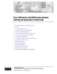
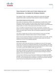
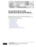
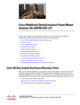
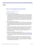
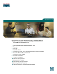
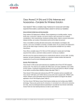
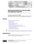
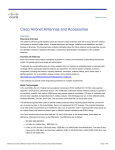
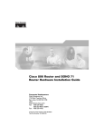
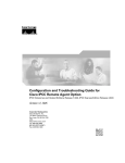
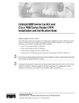
Cisco Multiband Wall-Mount Antenna
(AIR-ANTM5560P-R)
This document outlines the specifications and describes the AIR-ANTM5560P-R multiband wall-mount
antenna and contains the following sections:
•
Cisco 90-Day Limited Hardware Warranty Terms, page 1
•
Overview, page 3
•
Technical Specifications, page 3
•
System Requirements, page 7
•
Installation Guidelines, page 8
•
Safety Instructions, page 9
•
Installation Instructions, page 10
•
Obtaining Documentation, page 13
•
Documentation Feedback, page 14
•
Cisco Product Security Overview, page 14
•
Obtaining Technical Assistance, page 15
•
Obtaining Additional Publications and Information, page 17
Cisco 90-Day Limited Hardware Warranty Terms
There are special terms applicable to your hardware warranty and various services that you can use
during the warranty period. Your formal Warranty Statement, including the warranties and license
agreements applicable to Cisco software, is available on Cisco.com. Follow these steps to access and
download the Cisco Information Packet and your warranty and license agreements from Cisco.com.
1.
Launch your browser, and go to this URL:
http://www.cisco.com/univercd/cc/td/doc/es_inpck/cetrans.htm
The Warranties and License Agreements page appears.
Corporate Headquarters:
Cisco Systems, Inc., 170 West Tasman Drive, San Jose, CA 95134-1706 USA
© 2005 Cisco Systems, Inc. All rights reserved.
Cisco 90-Day Limited Hardware Warranty Terms
2.
To read the Cisco Information Packet, follow these steps:
a. Click the Information Packet Number field, and make sure that the part number
78-5235-03A0 is highlighted.
b. Select the language in which you would like to read the document.
c. Click Go.
The Cisco Limited Warranty and Software License page from the Information Packet appears.
d. Read the document online, or click the PDF icon to download and print the document in Adobe
Portable Document Format (PDF).
Note
3.
You must have Adobe Acrobat Reader to view and print PDF files. You can download
the reader from Adobe’s website: http://www.adobe.com
To read translated and localized warranty information about your product, follow these steps:
a. Enter this part number in the Warranty Document Number field:
78-5236-01C0
b. Select the language in which you would like to read the document.
c. Click Go.
The Cisco warranty page appears.
d. Review the document online, or click the PDF icon to download and print the document in
Adobe Portable Document Format (PDF).
You can also contact the Cisco service and support website for assistance:
http://www.cisco.com/public/Support_root.shtml.
Duration of Hardware Warranty
Ninety (90) days.
Replacement, Repair, or Refund Policy for Hardware
Cisco or its service center will use commercially reasonable efforts to ship a replacement part within ten
(10) working days after receipt of a Return Materials Authorization (RMA) request. Actual delivery
times can vary, depending on the customer location.
Cisco reserves the right to refund the purchase price as its exclusive warranty remedy.
To Receive a Return Materials Authorization (RMA) Number
Contact the company from whom you purchased the product. If you purchased the product directly from
Cisco, contact your Cisco Sales and Service Representative.
Complete the information below, and keep it for reference:
Company product purchased from
Company telephone number
Product model number
Product serial number
Maintenance contract number
Cisco Multiband Wall-Mount Antenna (AIR-ANTM5560P-R)
2
OL-6847-01
Overview
Overview
The AIR-ANTM5560P-R antenna operates in the 2.4- and 5-GHz bands, and is designed for use with
spatial-diversity access point (AP) systems. The AIR-ANTM5560P-R antenna is compatible with Cisco
802.11a/b/g radio products using a reverse-polarity threaded Neill-Concelman (RP-TNC) connector.
Figure 1 shows the AIR-ANTM5560P-R antenna.
Cisco AIR-ANTM5560P-R Antenna
135160
Figure 1
Technical Specifications
The following table lists the technical specifications for AIR-ANTM5560P-R.
Antenna type
Directional panel
Operating frequency range
1
Maximum VSWR bandwidth
Peak gain
Polarization
Azimuth plane beamwidth
Elevation plane 3 dB beamwidth (H-plane)
Elevation plane 3 dB beamwidth (E-plane)
2400 to 2500 MHz and 4900 to 5990 MHz
2.0:1
•
2.4-GHz: 5.5 dBi
•
5-GHz: 6 dBi
Linear vertical
•
2.4-GHz: 68 degrees
•
5-GHz: 52 degrees
•
2.4-GHz: 68 degrees
•
5-GHz: 52 degrees
•
2.4-GHz: 66 degrees
•
5-GHz: 60 degrees
Coaxial cable
10 ft (3 m) plenum rated
Dimensions
4.2 x 4.2 x 1.4 in. (106.7 x 106.7 x 35.6 mm)
Weight
0.5 lb (0.23 kg)
Cisco Multiband Wall-Mount Antenna (AIR-ANTM5560P-R)
OL-6847-01
3
Technical Specifications
Connector type
RP-TNC
Enclosure
Acrylic/PVC
Environment
Indoor only
Mounting
Wall-mount, pole-mount
1. VSWR = voltage standing wave ratio
Figure 2 shows the H-plane radiation pattern at 2.4- to 2.5-GHz for the AIR-ANTM5560P-R antenna.
Figure 2
H-Plane Pattern at 2.4- to 2.5-GHz
345
0
15
330
30
315
45
300
60
285
75
270
-30
-20
-10
90
dB
255
105
240
120
135
210
150
195
180
135126
225
165
Cisco Multiband Wall-Mount Antenna (AIR-ANTM5560P-R)
4
OL-6847-01
Technical Specifications
Figure 3 shows the E-plane radiation pattern at 2.4- to 2.5-GHz for the AIR-ANTM5560P-R antenna.
Figure 3
E-Plane Pattern at 2.4- to 2.5-GHz
345
0
15
330
30
315
45
300
60
285
75
270
-30
-20
-10
90
dB
255
105
240
120
135
210
150
195
180
135125
225
165
Cisco Multiband Wall-Mount Antenna (AIR-ANTM5560P-R)
OL-6847-01
5
Technical Specifications
Figure 4 shows the H-plane radiation pattern at 4.9- to 5.99-GHz for the AIR-ANTM5560P-R antenna.
Figure 4
H-Plane Pattern at 4.9- to 5.99-GHz
345
0
15
30
330
45
315
60
300
75
285
270
-30
-20
-10
90
dB
255
105
240
120
135
210
150
195
180
135127
225
165
Cisco Multiband Wall-Mount Antenna (AIR-ANTM5560P-R)
6
OL-6847-01
System Requirements
Figure 5 shows the E-plane radiation pattern at 4.9- to 5.99-GHz for the AIR-ANTM5560P-R antenna.
Figure 5
E-Plane Pattern at 4.9- to 5.99-GHz
345
0
15
30
330
45
315
60
300
75
285
270
-30
-20
-10
90
dB
255
105
240
120
135
210
150
195
180
135128
225
165
System Requirements
The AIR-ANTM5560P-R antenna requires a Cisco 802.11a/b/g radio product that uses a RP-TNC
connector.
Cisco Multiband Wall-Mount Antenna (AIR-ANTM5560P-R)
OL-6847-01
7
Installation Guidelines
Installation Guidelines
In addition to antenna orientation, wireless access point installation location with respect to all wireless
clients plays a significant role in determining overall network performance. Clients at the furthest
coverage points might have 10% to 50% of the bandwidth of clients close to it. Wireless network
coverage in one area or location might need to be lowered to improve the performance of other clients.
Because antennas transmit and receive radio signals, their performance can be adversely affected by the
surrounding environment including distance between access point and client, physical obstructions, or
radio frequency (RF) interference.
Follow these guidelines to ensure the best possible performance:
•
Mount the antenna to use its propagation characteristics. One way to do this is to orient the antenna
vertically and mount it as high as possible.
Note
This antenna must be mounted vertically in order to maximize its directional propagation
characteristics. Mounting it horizontally may noticeably decrease the antenna’s range and
overall performance.
•
Wherever possible, mount the AP HWIC and antenna where the wireless devices would be within
sight and avoid physical obstructions. Barriers along the line of sight between client and access point
will degrade the wireless radio signals. AP HWICs and antennas can be installed above floor level
in office environments or near the ceiling for better performance since most obstructions tend to be
near floor level.
•
The density of the materials used in a building's construction determines the number of walls the
signal must pass through and still maintain adequate coverage. Consider the following before
choosing the location to install your antenna:
– Paper and vinyl walls have very little effect on signal penetration.
– Solid and precast concrete walls limit signal penetration to one or two walls without degrading
coverage.
– Concrete and wood block walls limit signal penetration to three or four walls.
– A signal can penetrate five or six walls constructed of drywall or wood.
– A thick metal wall or wire-mesh stucco walls causes signals to reflect back and cause poor
penetration.
Caution
•
Avoid mounting the antenna next to a column or vertical support that could create a shadow zone
and reduce the coverage area.
•
Keep the antenna away from reflective metal objects such as heating and air-conditioning ducts,
large ceiling trusses, building superstructures, and major power cabling runs. If necessary, use an
extension cable to relocate the antenna away from these obstructions.
Install the AP HWIC and any antennas away from appliances that share the same frequency bands.
Microwave ovens, cordless telephones, and security monitors can temporarily interfere with wireless
performance.
Cisco Multiband Wall-Mount Antenna (AIR-ANTM5560P-R)
8
OL-6847-01
Safety Instructions
Caution
We recommend you avoid installing wireless antennas in or near rack-mounted installations that include
networking equipment and computer servers whose radiated noise emissions can severely degrade radio
performance.
•
To extend the coaxial cable included with your antenna, we recomend a low-loss or ultra-low-loss
coaxial cable for installation flexibility without a significant loss in range. The following table lists
transmission loss information about low-loss and ultra-low-loss extension coaxial cables available
from Cisco.
Cisco Product Number
Cable Length
AIR-CAB020LL-R
20 ft (6 m)
AIR-CAB050LL-R
AIR-CAB100ULL-R
AIR-CAB150ULL-R
50 ft (15 m)
100 ft (30 m)
150 ft (46 m)
Transmission Loss
•
2.4-GHz: 1.3 dBi
•
5-GHz: 2.5 dBi
•
2.4-GHz: 3.3 dBi
•
5-GHz: 5.75 dBi
•
2.4-GHz: 4.4 dBi
•
5-GHz: 7.25 dBi
•
2.4-GHz: 6.6 dBi
•
5-GHz: 11 dBi
Safety Instructions
Follow these safety precautions when installing your antenna.
Warning
In order to comply with FCC radio frequency (RF) exposure limits, antennas should be located at a
minimum of 7.9 inches (20 cm) or more from the body of all persons. Statement 332
•
Plan your installation procedure carefully and completely before you begin.
•
If you are installing an antenna for the first time, for your own safety as well as that of others, seek
professional assistance. Consult your dealer, who can explain which mounting method to use for the
location where you intend to install the antenna.
•
Choose your installation site with safety as well as performance in mind. Remember that electric
power lines and telephone lines look alike. For your safety, assume that any line is an electric power
line until determined otherwise.
•
Call your local power company or building maintenance organization if you are unsure about cables
close to your intended mounting location.
•
If an accident or emergency occurs with the power lines, call for qualified emergency help
immediately.
•
When installing your antenna in any location, do not use a metal ladder. Do dress properly: shoes
with rubber soles and heels, rubber gloves, and a long sleeved shirt or jacket. When drilling
mounting holes, wear safety glasses.
Cisco Multiband Wall-Mount Antenna (AIR-ANTM5560P-R)
OL-6847-01
9
Installation Instructions
Installation Instructions
The following sections contain procedures for installing the antenna on a wall or pole. The following
parts are included with your antenna:
•
Molded antenna mount
•
Molded wall mount
•
Articulating arm
•
Four 8-32 nylon lock nuts
•
Two 1/4-in. lock washers
•
Two 1/4-in. flat washers
•
Two 1/4-20 x 1-1/4-in. machine screws
•
Two 1/4-20 hex nuts
For mounting on a wall:
•
Four wall anchors
•
Four 8-18 x 3/4-in. self-tapping Phillips screws
For mounting on a pole:
•
Two worm tie clamps
Tools and Equipment Required
To install the antenna, you will need the following tools and equipment:
•
Adjustable wrench
•
A Phillips screwdriver
•
A pencil
For mounting on a wall:
•
A portable hand or electric drill
•
A 3/16 in. (4.7 mm) drill bit
For mounting on a pole:
•
A small flat-blade screwdriver
Mounting on a Wall
This section provides instructions for mounting the antenna on a wall. (See Figure 6.)
Cisco Multiband Wall-Mount Antenna (AIR-ANTM5560P-R)
10
OL-6847-01
Installation Instructions
Figure 6
Mounting the Antenna on a Wall
2
3
5
4
135159
1
3
1
Wall anchors
2
Molded wall mount
3
8-18 x 3/4-in. self-tapping Phillips screws
4
Articulating arm
5
Molded antenna mount
To mount the antenna on a wall, follow these steps:
Step 1
Choose a location for mounting.
Step 2
If an extension coaxial cable is used, connect it to the access point and extend the coaxial cable to the
location for mounting the antenna.
Step 3
Attach the antenna to the molded antenna mount using the four provided 8-32 nylon lock nuts.
Step 4
Attach the antenna mount to the articulating arm (all mounting hardware is provided):
a.
Place a 1/4-in. lock washer, then a 1/4-in. flat washer on a 1/4-20 x 1-1/4-in. machine screw.
b.
Insert the screw and washers, first through the molded antenna mount, then the articulating arm.
c.
Secure the articulating arm to the molded antenna mount using a 1/4-20 hex nut.
Step 5
Find the molded wall mount and position it on the mounting surface. Use a pencil to mark the location
of the mounting holes. There are four holes for wall-mounting, one in each corner.
Step 6
Using a 3/16-in. (4.7 mm) drill bit, drill holes for the screws at the locations you marked in Step 5.
Step 7
Route the cable either up or down from the wall or corner.
Step 8
Install a wall anchor in each hole.
Step 9
Line up the mounting holes on the molded wall mount with the pilot holes and start one of the provided
8-18 x 3/4-in. self-tapping Phillips screws in each hole.
Step 10
Tighten the screws with a Philips screwdriver.
Step 11
Attach the articulating arm to the molded wall mount (all hardware is provided):
a.
Place a 1/4-in. lock washer, then a 1/4-in. flat washer on a 1/4-20 x 1-1/4-in. machine screw.
b.
Insert the screw and washers, first through the molded wall mount, then the articulating arm.
c.
Secure the articulating arm to the molded wall mount using a 1/4-20 hex nut.
Cisco Multiband Wall-Mount Antenna (AIR-ANTM5560P-R)
OL-6847-01
11
Installation Instructions
Step 12
Loosen the screws on the articulating arm to position the antenna as desired. When you are finished
positioning the antenna, tighten all the screws.
Step 13
If an extension coaxial cable is used, connect it to the antenna cable.
Mounting on a Pole
This section provides instructions for mounting the antenna on a pole. (See Figure 7.)
Figure 7
Mounting the Antenna on a Pole
2
4
1
3
135161
1
1
Worm tie clamps
2
Molded wall mount
3
Articulating arm
4
Molded antenna mount
To mount the antenna on a pole, follow these steps:
Step 1
Choose a location for mounting. The diameter of the mast must be from 1.5 in. to 2.5 in. (25 mm to
70 mm).
Step 2
If an extension coaxial cable is used, connect it to the access point and extend the coaxial cable to the
location for mounting the antenna.
Step 3
Attach the antenna to the molded antenna mount using the four provided 8-32 nylon lock nuts.
Step 4
Attach the antenna mount to the articulating arm (all mounting hardware is provided):
a.
Place a 1/4-in. lock washer, then a 1/4-in. flat washer on a 1/4-20 x 1-1/4-in. machine screw.
b.
Insert the screw and washers, first through the molded antenna mount, then the articulating arm.
c.
Secure the articulating arm to the molded antenna mount using a 1/4-20 hex nut.
Step 5
Thread the two worm tie clamps provided through the four square holes of the molded wall mount.
Step 6
Wrap the worm tie clamps around the pole and tighten them using a small flat-head screwdriver.
Cisco Multiband Wall-Mount Antenna (AIR-ANTM5560P-R)
12
OL-6847-01
Obtaining Documentation
Step 7
Attach the articulating arm to the molded wall mount (all hardware is provided):
a.
Place a 1/4-in. lock washer, then a 1/4-in. flat washer on a 1/4-20 x 1-1/4” machine screw.
b.
Insert the screw and washers, first through the molded wall mount, then the articulating arm.
c.
Secure the articulating arm to the molded wall mount using a 1/4-20 hex nut.
Step 8
Loosen the screws on the articulating arm to position the antenna as desired. When you are finished
positioning the antenna, tighten all the screws.
Step 9
If an extension coaxial cable is used, connect it to the antenna cable.
Obtaining Documentation
Cisco documentation and additional literature are available on Cisco.com. Cisco also provides several
ways to obtain technical assistance and other technical resources. These sections explain how to obtain
technical information from Cisco Systems.
Cisco.com
You can access the most current Cisco documentation at this URL:
http://www.cisco.com/univercd/home/home.htm
You can access the Cisco website at this URL:
http://www.cisco.com
You can access international Cisco websites at this URL:
http://www.cisco.com/public/countries_languages.shtml
Documentation DVD
Cisco documentation and additional literature are available in a Documentation DVD package, which
may have shipped with your product. The Documentation DVD is updated regularly and may be more
current than printed documentation. The Documentation DVD package is available as a single unit.
Registered Cisco.com users (Cisco direct customers) can order a Cisco Documentation DVD (product
number DOC-DOCDVD=) from the Ordering tool or Cisco Marketplace.
Cisco Ordering tool:
http://www.cisco.com/en/US/partner/ordering/
Cisco Marketplace:
http://www.cisco.com/go/marketplace/
Cisco Multiband Wall-Mount Antenna (AIR-ANTM5560P-R)
OL-6847-01
13
Documentation Feedback
Ordering Documentation
You can find instructions for ordering documentation at this URL:
http://www.cisco.com/univercd/cc/td/doc/es_inpck/pdi.htm
You can order Cisco documentation in these ways:
•
Registered Cisco.com users (Cisco direct customers) can order Cisco product documentation from
the Ordering tool:
http://www.cisco.com/en/US/partner/ordering/
•
Nonregistered Cisco.com users can order documentation through a local account representative by
calling Cisco Systems Corporate Headquarters (California, USA) at 408 526-7208 or, elsewhere in
North America, by calling 1 800 553-NETS (6387).
Documentation Feedback
You can send comments about technical documentation to [email protected].
You can submit comments by using the response card (if present) behind the front cover of your
document or by writing to the following address:
Cisco Systems
Attn: Customer Document Ordering
170 West Tasman Drive
San Jose, CA 95134-9883
We appreciate your comments.
Cisco Product Security Overview
Cisco provides a free online Security Vulnerability Policy portal at this URL:
http://www.cisco.com/en/US/products/products_security_vulnerability_policy.html
From this site, you can perform these tasks:
•
Report security vulnerabilities in Cisco products.
•
Obtain assistance with security incidents that involve Cisco products.
•
Register to receive security information from Cisco.
A current list of security advisories and notices for Cisco products is available at this URL:
http://www.cisco.com/go/psirt
If you prefer to see advisories and notices as they are updated in real time, you can access a Product
Security Incident Response Team Really Simple Syndication (PSIRT RSS) feed from this URL:
http://www.cisco.com/en/US/products/products_psirt_rss_feed.html
Cisco Multiband Wall-Mount Antenna (AIR-ANTM5560P-R)
14
OL-6847-01
Obtaining Technical Assistance
Reporting Security Problems in Cisco Products
Cisco is committed to delivering secure products. We test our products internally before we release them,
and we strive to correct all vulnerabilities quickly. If you think that you might have identified a
vulnerability in a Cisco product, contact PSIRT:
Tip
•
Emergencies — [email protected]
•
Nonemergencies — [email protected]
We encourage you to use Pretty Good Privacy (PGP) or a compatible product to encrypt any sensitive
information that you send to Cisco. PSIRT can work from encrypted information that is compatible with
PGP versions 2.x through 8.x.
Never use a revoked or an expired encryption key. The correct public key to use in your correspondence
with PSIRT is the one that has the most recent creation date in this public key server list:
http://pgp.mit.edu:11371/pks/lookup?search=psirt%40cisco.com&op=index&exact=on
In an emergency, you can also reach PSIRT by telephone:
•
1 877 228-7302
•
1 408 525-6532
Obtaining Technical Assistance
For all customers, partners, resellers, and distributors who hold valid Cisco service contracts, Cisco
Technical Support provides 24-hour-a-day, award-winning technical assistance. The Cisco Technical
Support Website on Cisco.com features extensive online support resources. In addition, Cisco Technical
Assistance Center (TAC) engineers provide telephone support. If you do not hold a valid Cisco service
contract, contact your reseller.
Cisco Technical Support Website
The Cisco Technical Support Website provides online documents and tools for troubleshooting and
resolving technical issues with Cisco products and technologies. The website is available 24 hours a day,
365 days a year, at this URL:
http://www.cisco.com/techsupport
Access to all tools on the Cisco Technical Support Website requires a Cisco.com user ID and password.
If you have a valid service contract but do not have a user ID or password, you can register at this URL:
http://tools.cisco.com/RPF/register/register.do
Cisco Multiband Wall-Mount Antenna (AIR-ANTM5560P-R)
OL-6847-01
15
Obtaining Technical Assistance
Note
Use the Cisco Product Identification (CPI) tool to locate your product serial number before submitting
a web or phone request for service. You can access the CPI tool from the Cisco Technical Support
Website by clicking the Tools & Resources link under Documentation & Tools. Choose Cisco Product
Identification Tool from the Alphabetical Index drop-down list, or click the Cisco Product
Identification Tool link under Alerts & RMAs. The CPI tool offers three search options: by product ID
or model name; by tree view; or for certain products, by copying and pasting show command output.
Search results show an illustration of your product with the serial number label location highlighted.
Locate the serial number label on your product and record the information before placing a service call.
Submitting a Service Request
Using the online TAC Service Request Tool is the fastest way to open S3 and S4 service requests. (S3
and S4 service requests are those in which your network is minimally impaired or for which you require
product information.) After you describe your situation, the TAC Service Request Tool provides
recommended solutions. If your issue is not resolved using the recommended resources, your service
request is assigned to a Cisco TAC engineer. The TAC Service Request Tool is located at this URL:
http://www.cisco.com/techsupport/servicerequest
For S1 or S2 service requests or if you do not have Internet access, contact the Cisco TAC by telephone.
(S1 or S2 service requests are those in which your production network is down or severely degraded.)
Cisco TAC engineers are assigned immediately to S1 and S2 service requests to help keep your business
operations running smoothly.
To open a service request by telephone, use one of the following numbers:
Asia-Pacific: +61 2 8446 7411 (Australia: 1 800 805 227)
EMEA: +32 2 704 55 55
USA: 1 800 553-2447
For a complete list of Cisco TAC contacts, go to this URL:
http://www.cisco.com/techsupport/contacts
Definitions of Service Request Severity
To ensure that all service requests are reported in a standard format, Cisco has established severity
definitions.
Severity 1 (S1)—Your network is “down,” or there is a critical impact to your business operations. You
and Cisco will commit all necessary resources around the clock to resolve the situation.
Severity 2 (S2)—Operation of an existing network is severely degraded, or significant aspects of your
business operation are negatively affected by inadequate performance of Cisco products. You and Cisco
will commit full-time resources during normal business hours to resolve the situation.
Severity 3 (S3)—Operational performance of your network is impaired, but most business operations
remain functional. You and Cisco will commit resources during normal business hours to restore service
to satisfactory levels.
Severity 4 (S4)—You require information or assistance with Cisco product capabilities, installation, or
configuration. There is little or no effect on your business operations.
Cisco Multiband Wall-Mount Antenna (AIR-ANTM5560P-R)
16
OL-6847-01
Obtaining Additional Publications and Information
Obtaining Additional Publications and Information
Information about Cisco products, technologies, and network solutions is available from various online
and printed sources.
•
Cisco Marketplace provides a variety of Cisco books, reference guides, and logo merchandise. Visit
Cisco Marketplace, the company store, at this URL:
http://www.cisco.com/go/marketplace/
•
Cisco Press publishes a wide range of general networking, training and certification titles. Both new
and experienced users will benefit from these publications. For current Cisco Press titles and other
information, go to Cisco Press at this URL:
http://www.ciscopress.com
•
Packet magazine is the Cisco Systems technical user magazine for maximizing Internet and
networking investments. Each quarter, Packet delivers coverage of the latest industry trends,
technology breakthroughs, and Cisco products and solutions, as well as network deployment and
troubleshooting tips, configuration examples, customer case studies, certification and training
information, and links to scores of in-depth online resources. You can access Packet magazine at
this URL:
http://www.cisco.com/packet
•
iQ Magazine is the quarterly publication from Cisco Systems designed to help growing companies
learn how they can use technology to increase revenue, streamline their business, and expand
services. The publication identifies the challenges facing these companies and the technologies to
help solve them, using real-world case studies and business strategies to help readers make sound
technology investment decisions. You can access iQ Magazine at this URL:
http://www.cisco.com/go/iqmagazine
•
Internet Protocol Journal is a quarterly journal published by Cisco Systems for engineering
professionals involved in designing, developing, and operating public and private internets and
intranets. You can access the Internet Protocol Journal at this URL:
http://www.cisco.com/ipj
•
World-class networking training is available from Cisco. You can view current offerings at
this URL:
http://www.cisco.com/en/US/learning/index.html
CCVP, the Cisco logo, and the Cisco Square Bridge logo are trademarks of Cisco Systems, Inc.; Changing the Way We Work, Live, Play, and Learn is a
service mark of Cisco Systems, Inc.; and Access Registrar, Aironet, BPX, Catalyst, CCDA, CCDP, CCIE, CCIP, CCNA, CCNP, CCSP, Cisco, the Cisco
Certified Internetwork Expert logo, Cisco IOS, Cisco Press, Cisco Systems, Cisco Systems Capital, the Cisco Systems logo, Cisco Unity,
Enterprise/Solver, EtherChannel, EtherFast, EtherSwitch, Fast Step, Follow Me Browsing, FormShare, GigaDrive, HomeLink, Internet Quotient, IOS,
iPhone, IP/TV, iQ Expertise, the iQ logo, iQ Net Readiness Scorecard, iQuick Study, LightStream, Linksys, MeetingPlace, MGX, Networking Academy,
Network Registrar, PIX, ProConnect, ScriptShare, SMARTnet, StackWise, The Fastest Way to Increase Your Internet Quotient, and TransPath are
registered trademarks of Cisco Systems, Inc. and/or its affiliates in the United States and certain other countries.
All other trademarks mentioned in this document or Website are the property of their respective owners. The use of the word partner does not imply a
partnership relationship between Cisco and any other company. (0709R)
Copyright © 2005 Cisco Systems, Inc. All rights reserved.
Cisco Multiband Wall-Mount Antenna (AIR-ANTM5560P-R)
OL-6847-01
17
Obtaining Additional Publications and Information
Cisco Multiband Wall-Mount Antenna (AIR-ANTM5560P-R)
18
OL-6847-01