1
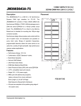
168PIN PC100 Unbuffered DIMM 512MB With 32MX8 CL2 TS64MLS64V8F2 Description Placement The TS64MLS64V8F2 is a 64M bit x 64 Synchronous Dynamic RAM high-density for PC-100. The TS64MLS64V8F2 consists of 16pcs CMOS 32Mx8 bits Synchronous DRAMs in TSOP-II 400mil packages and a 2048 bits serial EEPROM on a 168-pin printed circuit board. The TS64MLS64V8F2 is a Dual In-Line Memory Module and is intended for mounting into 168-pin edge connector sockets. Synchronous design allows precise cycle control with the use of system clock. I/O transactions are possible on every clock cycle. Range of operation frequencies, A programmable latencies allow the same device to be useful for a variety of high bandwidth, high performance memory system applications. B Features D • Performance Range: PC-100. • Conformed to JEDEC Standard Spec. E • Burst Mode Operation. C • Auto and Self Refresh. • CKE Power Down Mode. • DQM Byte Masking (Read/Write) H • Serial Presence Detect (SPD) with serial EEPROM G • LVTTL compatible inputs and outputs. F • Single 3.3V ± 0.3V power supply. PCB:09-7308 • MRS cycle with address key programs. Latency (Access from column address) Burst Length (1,2,4,8 & Full Page) Data Sequence (Sequential & Interleave) • All inputs are sampled at the positive going edge of the system clock. Transcend information Inc I E 1 168PIN PC100 Unbuffered DIMM 512MB With 32MX8 CL2 TS64MLS64V8F2 Pin Identification Dimensions Symbol Side Millimeters Inches A 133.35±0.40 5.250±0.016 B 65.67 2.585 C 23.49 0.925 D 8.89 0.350 E 3.00 0.118 F 29.21±0.20 1.150±0.008 G 19.80 0.788 H 15.80 0.622 I 1.27±0.10 0.050±0.004 (Refer Placement) Transcend information Inc Function A0~A12, BA0, BA1 Address input DQ0~DQ63 Data Input / Output CLK0~CLK3 Clock Input CKE0, CKE1 Clock Enable Input /CS0~/CS3 Chip Select Input /RAS Row Address Strobe /CAS Column Address Strobe /WE Write Enable DQM0~DQM7 Data (DQ) Mask SA0~SA2 Address in EEPROM SCL Serial PD Clock SDA Serial PD Add/Data input/output Vcc +3.3 Voltage Power Supply Vss Ground NC No Connection 2 168PIN PC100 Unbuffered DIMM 512MB With 32MX8 CL2 TS64MLS64V8F2 Pinouts: Pin Pin Pin Pin No Name No Name 01 Vss 43 Vss 02 DQ0 44 NC 03 DQ1 45 /CS2 04 DQ2 46 DQM2 05 DQ3 47 DQM3 06 Vcc 48 NC 07 DQ4 49 Vcc 08 DQ5 50 NC 09 DQ6 51 NC 10 DQ7 52 *C2 11 DQ8 53 *C3 12 Vss 54 Vss 13 DQ9 55 DQ16 14 DQ10 56 DQ17 15 DQ11 57 DQ18 16 DQ12 58 DQ19 17 DQ13 59 Vcc 18 Vcc 60 DQ20 19 DQ14 61 NC 20 DQ15 62 *Vref 21 *C0 63 *CKE1 22 *C1 64 Vss 23 Vss 65 DQ21 24 NC 66 DQ22 25 NC 67 DQ23 26 Vcc 68 Vss 27 /WE 69 DQ24 28 DQM0 70 DQ25 29 DQM1 71 DQ26 30 /CS0 72 DQ27 31 NC 73 Vcc 32 Vss 74 DQ28 33 A0 75 DQ29 34 A2 76 DQ30 35 A4 77 DQ31 36 A6 78 Vss 37 A8 79 *CLK2 38 A10/AP 80 NC 39 BA1 81 NC 40 Vcc 82 SDA 41 Vcc 83 SCL 42 CLK0 84 Vcc *Please refer Block Diagram Transcend information Inc Pin No 85 86 87 88 89 90 91 92 93 94 95 96 97 98 99 100 101 102 103 104 105 106 107 108 109 110 111 112 113 114 115 116 117 118 119 120 121 122 123 124 125 126 3 Pin Name Vss DQ32 DQ33 DQ34 DQ35 Vcc DQ36 DQ37 DQ38 DQ39 DQ40 Vss DQ41 DQ42 DQ43 DQ44 DQ45 Vcc DQ46 DQ47 *C4 *C5 Vss NC NC Vcc /CAS DQM4 DQM5 */CS1 /RAS Vss A1 A3 A5 A7 A9 BA0 A11 Vcc *CLK1 *A12 Pin No 127 128 129 130 131 132 133 134 135 136 137 138 139 140 141 142 143 144 145 146 147 148 149 150 151 152 153 154 155 156 157 158 159 160 161 162 163 164 165 166 167 168 Pin Name Vss CKE0 */CS3 DQM6 DQM7 *A13 Vcc NC NC *C6 *C7 Vss DQ48 DQ49 DQ50 DQ51 Vcc DQ52 NC *Vref *REGE Vss DQ53 DQ54 DQ55 Vss DQ56 DQ57 DQ58 DQ59 Vcc DQ60 DQ61 DQ62 DQ63 Vss *CLK3 NC SA0 SA1 SA2 Vcc 168PIN PC100 Unbuffered DIMM 512MB With 32MX8 CL2 TS64MLS64V8F2 Block Diagram CKE0 CKE /CAS /CAS /WE /WE /CS /CS CKE DQM1 DQM0 CKE /CAS /WE /CS CKE DQM2 DQM3 32Mx8 SDRAM CLK /CS0 /WE /CS /RAS 32Mx8 SDRAM DQM /WE /RAS 32Mx8 SDRAM CLK /CAS A0~A12, BA0,BA1 DQ0~DQ7 CLK /CAS 32Mx8 SDRAM A0~A12, BA0,BA1 DQ0~DQ7 DQM /RAS CLK /RAS A0~A12, BA0,BA1 DQ0~DQ7 /RAS DQM A0~A12, BA0,BA1 DQ0~DQ7 DQM A0~A12 BA0,BA1 DQ0~DQ63 /CS2 A0~A12, BA0,BA1 DQ0~DQ7 A0~A12, BA0,BA1 DQ0~DQ7 /RAS 32Mx8 /RAS /RAS /RAS 32Mx8 /CAS SDRAM /CAS /CAS SDRAM DQM7 A0~A12, BA0,BA1 DQ0~DQ7 A0~A12, BA0,BA1 DQ0~DQ7 A0~A12, BA0,BA1 DQ0~DQ7 A0~A12, BA0,BA1 DQ0~DQ7 /RAS 32Mx8 /RAS /CAS SDRAM /CAS /RAS DQM0 DQM1 DQM2 DQM3 A0~A12, BA0,BA1 DQ0~DQ7 A0~A12, BA0,BA1 DQ0~DQ7 A0~A12, BA0,BA1 DQ0~DQ7 A0~A12, BA0,BA1 DQ0~DQ7 DQM4 DQM5 SCL Serial EEPROM SCL SDA A0 A1 A2 CKE DQM6 /RAS /CAS /WE /CS CKE 32Mx8 SDRAM DQM CKE /WE /CS 32Mx8 SDRAM CLK /WE /CS /RAS /CAS DQM 32Mx8 SDRAM CLK CKE /RAS /CAS DQM /WE /CS 32Mx8 SDRAM CLK /RAS /CAS CLK CKE DQM CKE CLK /WE /CS DQM /WE /CS CKE 32Mx8 /CAS SDRAM /WE CLK CKE 32Mx8 SDRAM /CS DQM CKE1 CLK /WE /CS DQM /CS1 32Mx8 SDRAM CLK CLK DQM CLK DQM CLK DQM CKE DQM6 /RAS CLK1 CLK3 /WE /CS DQM5 /CAS /CS3 CKE 32Mx8 SDRAM DQM4 DQM CLK0 CLK2 CKE /CAS /WE /CS /WE /CS /WE /CS CKE 32Mx8 SDRAM CLK A0~A12, BA0,BA1 DQ0~DQ7 DQM A0~A12, BA0,BA1 DQ0~DQ7 DQM7 SDA SA0 SA1 SA2 This technical information is based on industry standard data and tests believed to be reliable. However, Transcend makes no warranties, either expressed or implied, as to its accuracy and assumes no liability in connection with the use of this product. Transcend reserves the right to make changes in specifications at any time without prior notice. Transcend information Inc 4 168PIN PC100 Unbuffered DIMM 512MB With 32MX8 CL2 TS64MLS64V8F2 ABSOLUTE MAXIMUM RATINGS Parameter Voltage on any pin relative to Vss Voltage on VDD supply to Vss Storage temperature Power dissipation Short circuit current Mean time between failure Temperature Humidity Burning Temperature Cycling Test Note: Symbol VIN, VOUT VDD, VDDQ TSTG PD IOS MTBF THB TC Value -1.0 ~ 4.6 -1.0 ~ 4.6 -55 ~ +150 16 50 50 85°C/85%, Static Stress 0°C ~ 125°C Cycling Unit V V °C W mA year °C-% °C Permanent device damage may occur if ABSOLUTE MAXIMUM RATINGS are exceeded. Functional operation should be restricted to recommended operating condition. Exposure to higher than recommended voltage for extended periods of time could affect device reliability. DC OPERATING CONDITIONS AND CHARACTERISTICS Recommended operating conditions (Voltage referenced to Vss = 0V, TA = 0 to 70°C) Parameter Symbol Min Typ Max Unit Supply voltage VDD 3.0 3.3 3.6 V Input high voltage VIH 2.0 3.0 VDD+0.3 V Input low voltage VIL -0.3 0 0.8 V Output high voltage VOH 2.4 V Output low voltage VOL 0.4 V Input leakage current (Inputs) IIL -10 10 uA Input leakage current (I/O pins) IIL uA Note 1 2 IOH=-2mA IOL=2mA 3 - Note: 1. VIH (max) = 5.6V AC .The overshoot voltage duration is ≤ 3ns. 2. VIL (min) = -2.0V AC .The undershoot voltage duration is ≤ 3ns. 3. Any input 0V ≤ VIN ≤ VDDQ. Input leakage currents include Hi-Z output leakage for all bi-directional buffers with Tri-State outputs. 4. Dout is disabled, 0V ≤ VOUT ≤ VDDQ. Transcend information Inc 5 168PIN PC100 Unbuffered DIMM 512MB With 32MX8 CL2 TS64MLS64V8F2 CAPACITANCE (VDD = 3.3V, TA = 20°C, f = 1MHz, VREF = 1.4V ± 200 mV) Parameter Input capacitance (A0~A12, BA0~ BA1) Input capacitance (/RAS, /CAS, /WE) Input capacitance (CKE0, CKE1) Input capacitance (CLK0~CLK3) Input capacitance (/CS0~/CS3) Input capacitance (DQM0~DQM7) Data input/output capacitance (DQ0~DQ63) Symbol Min Max Unit CIN1 CIN2 CIN3 CIN4 CIN5 CIN6 COUT1 45 45 25 15 15 10 13 85 85 45 21 25 15 18 pF pF pF pF pF pF pF DC CHARACTERISTICS (Recommended operating condition unless otherwise noted, TA = 0 to 70°C) Parameter Operating Current (One Bank Active) Symbol Test Condition Value (Typ) Unit Note ICC1 Burst Length =1 tRC≥tRC(min) IOL=0mA 1,120 mA 1 ICC2P Precharge Standby Current ICC2PS in power-down mode ICC2N Precharge Standby Current in non power-down mode Active Standby Current in power-down mode Active Standby Current in non power-down mode (One Bank Active) ICC2NS 32 CKE & CLK≤VIL(max), tCC=∞ 32 CKE≥VIH(min), /CS≥VIH(min), tCC=10ns Input signals are changed one time during 20ns CKE≥VIH(min), CLK≤VIL(max), tCC=∞ Input signals are stable 224 CKE≤VIL(max), tCC=10ns 96 ICC3PS CKE & CLK≤VIL(max), tCC=∞ 96 ICC3N ICC3NS ICC4 Refresh Current ICC5 Self Refresh Current ICC6 CKE≥VIH(min), /CS≥VIH(min), tCC=10ns Input signals are changed one time during 20ns CKE≥VIH(min), CLK≤VIL(max), tCC=∞ Input signals are stable IOL= 0 mA Page Burst tccD = 2CLKs mA mA 480 400 mA 1,160 mA 1 tRC≥tRC(min) 1,840 mA 2 CKE≤0.2V 80 mA 1. Measured with outputs open. 2. Refresh period is 64ms. Transcend information Inc mA 256 ICC3P Operating Current (Bust Mode) Note: CKE≤VIL(max), tCC=10ns 6 168PIN PC100 Unbuffered DIMM 512MB With 32MX8 CL2 TS64MLS64V8F2 AC OPERATING TEST CONDITIONS (VDD = 3.3V,0.3V, TA = 0 to 70°C) Parameter AC Input levels (VIH/VIL) Input timing measurement reference level Input rise and fall time Output timing measurement reference level Output load condition Value 2.4/0.4 1.4 tr/tf=1/1 1.4 See Fig. 2 Vtt=1.4V 3.3V 50 Ohm 1200 Ohm Output VOH (DC)=2.4V, IOH=-2mA VOL (DC)=0.4V, I OL=2mA Output Z0=50 Ohm 50pF 50pF 870 Ohm Unit V V ns V (Fig. 2) AC Output Load Circuit (Fig. 1) DC Output Load Circuit OPERATING AC PARAMETER (AC operating conditions unless otherwise noted) Parameter Symbol Value Unit Note Row active to row active delay tRRD(min) 20 ns 1 /RAS to /CAS delay tRCD(min) 20 ns 1 Row precharge time tRP(min) 20 ns 1 tRAS(min) 50 ns 1 tRAS(max) 100 us Row cycle time tRC(min) 70 ns 1 Last data in to new col. address delay tCDL(min) 1 CLK 2 Last data in to row precharge tRDL(min) 2 CLK 2 Last data in to burst stop tBDL(min) 1 CLK 2 Col. address to col. address delay tCCD(min) 1 CLK 3 Row active time Number of valid output data 2 ea Note: 1. The minimum number of clock cycles is determined by dividing the minimum time required with clock cycle time, and then rounding off to the next higher integer. 2. Minimum delay is required to complete write. 3. All parts allow every cycle column address change. 4. In case of row precharge interrupt, auto precharge and read burst stop. Transcend information Inc 7 4 168PIN PC100 Unbuffered DIMM 512MB With 32MX8 CL2 TS64MLS64V8F2 AC CHARACTERISTICS (AC operating conditions unless otherwise noted) Refer to the individual component, not the whole module. Parameter Symbol Min Max Unit Note CLK cycle time tCC 10 1000 ns 1 CLK to valid output delay tSAC - 6.0 ns 1, 2 Output data hold time tOH 3.0 - ns 2 CLK high pulse width tCH 3.0 - ns 3 CLK low pulse width tCL 3.0 - ns 3 Input setup time tSS 2.0 - ns 3 Input hold time tSH 1.0 - ns 3 CLK to output in Low-Z tSLZ 1.0 - ns 2 CLK to output in Hi-Z 6.0 ns tSHZ 1. Parameters depend on programmed CAS latency. Note: 2. If clock rising time is longer than 1ns, (tr/2-0.5)ns should be added to the parameter. 3. Assumed input rise and fall time (tr & tf)= 1ns. If tr & tf is longer than 1ns, transient time compensation should be considered, i.e., [(tr + tf)/2-1]ns should be added to the parameter. Transcend information Inc 8 168PIN PC100 Unbuffered DIMM 512MB With 32MX8 CL2 TS64MLS64V8F2 SIMPLIFIED TRUTH TABLE COMMAND Register Mode Register Set Refresh Auto Refresh Entry Self Refresh Exit CKEn-1 CKEn (V=Valid, X=Don’t Care, H=Logic High, L=Logic Low) A11, A12 DQM BA0,1 A10/AP Note A0~A9 /CS /RAS /CAS /WE H X L L L L X OP CODE H H L L L L H X X L H L H H X H X H X X X H X L L H H X V H X L H L H X V H X L H L L X V H X L H H L X H X L L H L X Clock Suspend or Entry Active Power Down Exit H L H L X V X V X V X L H X X X X X H X X X Entry H L L H H H H X X X L V V V Bank Active & Row Addr. Read & Column Address Auto Precharge Disable Write & Column Address Auto Precharge Disable Auto Precharge Enable Auto Precharge Enable Burst Stop Bank Selection Both Banks Precharge Precharge Power Down Mode 3 3 3 3 Row Address L H L H X L H Column Address (A0~A9) Column Address (A0~A9) 4 4, 5 4 4, 5 6 X X X X Exit L DQM H No Operation Command H Note: V X 1,2 H X X H X X X L H H H X V X X X 1. OP Code: Operand Code A0~A12, BA0~BA1: Program keys. (@MRS) 2. MRS can be issued only at both banks precharge state. A new command can be issued after 2 CLK cycles of MRS. 3. Auto refresh functions are as same as CBR refresh of DRAM. The automatical precharge without row precharge command is meant by “Auto”. Auto/self refresh can be issued only at both banks precharge state. 4. BA0~BA1: Bank select address. If both BA0 and BA1 are “Low” at read, write, row active and precharge, bank A is selected. If both BA0 is “Low” and BA1 is “High” at read, write, row active and precharge, bank B is selected. If both BA0 is “High” and BA1 is “Low” at read, write, row active and precharge, bank C is selected. If both BA0 and BA1 are “High” at read, write, row active and precharge, bank D is selected. If A10/AP is “High” at row precharge, BA0 and BA1 are ignored and both banks are selected. 5. During burst read or write with auto precharge, new read/write command cannot be issued. Another bank read/write command can be issued after the end of burst. New row active of the associated bank can be issued at tRP after the end of burst. 6. Burst stop command is valid at every burst length. 7. DQM sampled at positive going edged of a CLK masks the data-in at the very CLK (Write DQM latency is 0), but makes Hi-Z state the data-out of 2 CLK cycles after. (Read DQM latency is 2) Transcend information Inc 9 7 168PIN PC100 Unbuffered DIMM 512MB With 32MX8 CL2 TS64MLS64V8F2 SERIAL PRESENCE DETECT SPECIFICATION Serial Presence Detect Byte No. Function Described Standard Specification Vendor Part 0 # of Bytes Written into Serial Memory 128bytes 80 1 Total # of Bytes of S.P.D Memory 256bytes 08 2 Fundamental Memory Type SDRAM 04 3 # of Row Addresses on this Assembly 13 0D 4 # of Column Addresses on this Assembly 10 0A 5 # of Module Banks on this Assembly 2 bank 02 6 Data Width of this Assembly 64bits 40 7 Data Width Continuation - 00 8 Voltage Interface Standard of this Assembly LVTTL3.3V 01 9 SDRAM Cycle Time (highest CAS latency) 10.0ns A0 10 SDRAM Access from Clock (highest CL) 6.0ns 60 11 DIMM configuration type (non-parity, ECC) Non parity 00 12 Refresh Rate Type 7.8us/Self Refresh 82 13 Primary SDRAM Width X8 08 14 Error Checking SDRAM Width None 00 15 Min Clock Delay Back to Back Random Address 1 clock 01 16 Burst Lengths Supported 1,2,4,8 & Full page 8F 17 Number of banks on each SDRAM device 4 bank 04 18 CAS # Latency 2&3 06 19 CS # Latency 0 clock 01 20 Write Latency 0 clock 01 21 SDRAM Module Attributes Non Buffer 00 Prec All, Auto Prec, R/W Burst 0E 10.0ns A0 6.0ns 60 - 00 - 00 22 SDRAM Device Attributes: General 23 SDRAM Cycle Time (2nd highest CL) 24 25 nd SDRAM Access from Clock (2 highest CL) rd SDRAM Cycle Time (3 highest CL) rd 26 SDRAM Access from Clock (3 highest CL) 27 Minimum Row Precharge Time 20ns 14 28 Minimum Row Active to Row Activate 20ns 14 Transcend information Inc 10 168PIN PC100 Unbuffered DIMM 512MB With 32MX8 CL2 TS64MLS64V8F2 29 Minimum RAS to CAS Delay 20ns 14 30 Minimum RAS Pulse Width 50ns 32 31 Density of Each Bank on Module 1row of 256MB 40 32 Command/Address Setup Time 2.0ns 20 33 Command/Address Hold Time 1.0ns 10 34 Data Signal Setup Time 2.0ns 20 35 Data Signal Hold Time 1.0ns 10 00 12 3A 7F, 4F 54 36-61 62 63 64-71 72 Superset Information SPD Data Revision Code Checksum for Bytes 0-62 Manufacturers JEDEC ID Code per JEP-108E Manufacturing Location VER 1.2 Transcend T 54 53 36 34 4D 4C 73-90 Manufacturers Part Number TS64MLS64V8F2 53 36 34 56 38 46 91-92 93-94 95-98 99-125 126 127 128~ Revision Code Manufacturing Date Assembly Serial Number Manufacturer Specific Data Intel Specification Frequency Intel Specification CAS# Latency/Clock Signal Support Unused Storage Locations By Manufactory By Manufactory 100MHz CL=2, 3 Clock 0~3 Open 32 20 20 20 20 20 0 Variable Variable 0 64 F4 FF Transcend information Inc 11