1
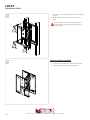
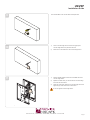
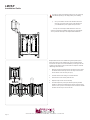
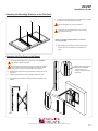
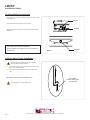
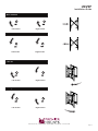
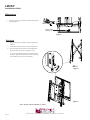
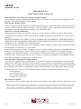
LMVSP
Installation Guide
Release Pop Out Ultra Slim Portrait Mount
www.mounts.com | North America 800.368.9700 | International +1-714-632-7100
1321 S. State College Blvd., Fullerton, CA 92831 USA
LMVSP
Maximum Flat Panel Weight:
100 lb. / 45.35 kg.
Installation Guide
Included Components
Wall Mount
(Qty 1)
5/16” Flat Washers
(Qty 4)
Universal Spacers
(Qty 12)
M6 x 12mm
(Qty 6)
M4 x 16mm
(Qty 6)
M4 x 25mm
M6 x 16mm
Bracket
(Qty 1 Pair)
Thread Depth Indicator
(Qty 1)
M5 Allen Driver
(Qty 1)
5/16” Concrete Wedge Anchors
(Qty 4)
5/16” x 3” Lag Bolts
(Qty 4)
M4 x 12mm
Extension Bracket
(Qty 1 Pair)
M8 Washers
(Qty 4)
(Qty 6)
(Qty 6)
M6 x 25mm
(Qty 6)
(Qty 6)
M8 x 25mm
(Qty 6)
M5 x 25mm
(Qty 6)
M8 x 16mm
(Qty 6)
M5 x 16mm
M8 Nylon Nut
(Qty 4)
M8 x 12mm
(Qty 6)
M5 x 12mm
Universal Washers
(Qty 6)
(Qty 6)
(Qty 6)
Required for installation
Electronic Stud Finder
Level
Page 2
Pencil
10mm Socket
Protective Eyewear
13mm or 1/2” Socket
M6 or 1/4” Drill Bit
Phillips Head Screwdriver
M8 or 5/16” Concrete Drill Bit
Socket Wrench
www.mounts.com | North America 800.368.9700 | International +1-714-632-7100
Portable Drill
LMVSP
Installation Guide
Wood Stud Installation
1
You must secure the mount to two (2) wall studs with four (4)
lag bolts (2 lag bolts for each stud found).
X
1)
Use a stud finder to determine the wall studs in the vicinity of the
mount.
2)
Use a pencil to mark each of the wall studs.
X
2
Two people are recommended for this step; one person to level the
mount and another person to mark the wall stud location.
1)
Place the mount against the wall in the desired viewing location.
2)
Use a pencil to mark the upper right mounting location
www.mounts.com | North America 800.368.9700 | International +1-714-632-7100
Page 3
LMVSP
Installation Guide
3
Drill a “pilot hole” on the upper right mark using a M6 or 1/4” drill bit and
power drill.
X
X
4
1)
Place the mount against the wall and align it with the pilot hole.
2)
Insert one (1) 5/16” x 3˝ lag bolt and one (1) 5/16”washer into the
upper right pilot hole.
3)
Use a socket wrench and a 13mm or 1/2” socket to tighten the lag
bolt.
Do not over tighten the lag bolt.
Page 4
www.mounts.com | North America 800.368.9700 | International +1-714-632-7100
LMVSP
Installation Guide
5
1)
Level the mount using a leveler
2)
Use a pencil to mark the remaining three (3) mounting locations
of each wall studs.
6
Drill a “pilot hole” on each of the marks with a power drill and a M6 or
1/4″ drill bit.
www.mounts.com | North America 800.368.9700 | International +1-714-632-7100
Page 5
LMVSP
Installation Guide
7
1)
Insert one (1) 5/16” x 3″ lag bolt and one (1) 5/16” washer into each
pilot hole
2)
Tighten all lag bolts using a socket wrench and 13mm or 1/2”
socket.
Do not over tighten the lag bolts when attaching the mount to
the wall. Improper installation may result in personal injury or
property damage.
8
Page 6
Concrete wall Installation
1)
Place the mount against the wall in the desired viewing location.
2)
Use a pencil to mark the upper right mounting location
www.mounts.com | North America 800.368.9700 | International +1-714-632-7100
LMVSP
Installation Guide
9
10
11
Use a drill and M8 or 5/16” concrete drill bit to drill a pilot hole.
1)
Insert a concrete wedge anchor into the hole. Lightly tap the
concrete wedge anchor into place with a hammer.
2)
Remove the nut and washer from the concrete wedge anchor.
1)
Place the LMVSP against the wall over the threaded shaft of the
concrete wedge anchor.
2)
Replace the washer which you removed from the concrete wedge
anchor with the 5/16” washer.
3)
Attach the nut and 5/16” washer to the concrete wedge anchor and
tighten using a socket wrench and a 10mm socket.
Do not over tighten concrete wedge anchor
www.mounts.com | North America 800.368.9700 | International +1-714-632-7100
Page 7
LMVSP
Installation Guide
12
1)
Level the LMVSP using a leveler
2)
Mark up the remaining three (3) mounting locations.
3)
Remove the LMVSP
13
Use a drill and M8 or 5/16” concrete drill bit to drill three (3) pilot holes.
14
1)
Insert the concrete wedge anchors into each hole. Lightly tap each
concrete wedge anchors into place with a hammer.
2)
Remove the nuts and washers from the concrete wedge anchors.
Page 8
www.mounts.com | North America 800.368.9700 | International +1-714-632-7100
LMVSP
Installation Guide
15
1)
Place the LMVSP against the wall over the threaded shafts of the
concrete wedge anchors.
2)
Replace the washers which you removed from the concrete wedge
anchors with the 5/16” washers.
3)
Attach the nuts and 5/16” washers to the concrete wedge anchors
and tighten using a socket wrench and a M10 socket.
Do not over tighten concrete wedge anchor
Installing OPTIONAL Model Specific Spacers
LMVSP ’s dedicated flat-panel spacers are engineered with the knowledge
that aligning each flat-panel on a large wall is time consuming and costly.
These model-specific spacers are available for most flat-panels, which
significantly reduces the installation time. (Call Customer Service to inquire
about model specific spacers.)
www.mounts.com | North America 800.368.9700 | International +1-714-632-7100
Page 9
LMVSP
Installation Guide
This spacer is shown for illustration purposes only. Your spacer may
look different depending on the display model you are installing.
1)
Once your LMVSP is mounted in the desired location and is
level, align your spacer to the top left or right (depending on
your install direction) corner register tabs of your mount.
You may use commercially available hardware to secure the
spacer to the wall during installation (depending on the wall material).
You may utilize the same spacer for multiple LMVSP installations.
Multiple LMVSP mounts can be installed using model specific spacers.
Simply repeat step one when installing each of the surrounding LMVSP
mounts. Use one spacer for each 2x2 installation by mounting it to the wall,
or utilize the same spacer as many times needed to complete an unlimited
LMVSP large matrix video wall.
Start
Page 10
1.
Make sure the spacer is plumb and level and mark each corner where
the LMVSP will be mounted (or secure to the wall). It is best to start
from the bottom corner and work your way up.
2.
Install the second mount working in a horizontal direction.
3.
Ensure that the mount remains plumb and level.
4.
Repeat this step for each mount horizontally
5.
To install multiple rows, place spacer between previously installed
LMVSP’s on the bottom row. Make sure the spacer is plumb and level,
mark the corners (or secure to the wall) to be sure of where the LMVSP
should be and secure your mount to the wall.
www.mounts.com | North America 800.368.9700 | International +1-714-632-7100
LMVSP
Installation Guide
Selecting the Mounting Hardware
1) Insert a small straw or toothpick into the threaded
inserts found on the back of the flat-panel.
2) Use a pencil to mark the depth of the threaded
insert on the small straw or toothpick.
3) Mark the straw or toothpick 1/8” above the depth of
the threaded insert, as shown in Figure 1.
4) Insert the small straw or toothpick into the remaining
threaded inserts to compare and verify their depth
using the straw or toothpick’s 1/8” allowance mark.
5) Locate the correct diameter screw for the threaded
insert.
Marking the 1/8”
Allowance
If the screw you selected is longer than the 1/8”
allowance mark on the small straw or toothpick,
as shown in Figure 2 and Figure 3, do not use
this screw. The screw length must not bypass the
mark.
6) Test each size of the screws provided.
Small Straw or Toothpick
Small Straw
or Toothpick
The correct screws should thread easily into the
mounting point and not pull out when tension is
applied.
Depth Plus 1/8” Allowance
Mark
Small Straw
or Toothpick
Depth Plus 1/8” Allowance
Mark
Securing the Adapters
Optional adapters are available with your LMVSP mount.
Secure the adapters to the LMVSP brackets with the supplied
TOP
(4) M8 washers and (4) M8 nuts.
P
TO
OM
TT
BO
www.mounts.com | North America 800.368.9700 | International +1-714-632-7100
BOTTOM
Page 11
LMVSP
Installation Guide
Universal Washer Installation
Premier Mounts’ Universal Washers are designed to
accommodate the various M4, M5, M6 and M8 hole sizes
required by flat-panels.
Do not place excessive pressure on the back of the
flat-panel, as this may damage your flat-panel.
M8
M5, M6
M4
The Universal Washer must be installed between
the head of the mounting screw and the mounting
bracket as shown.
Universal Spacer Installation
Mounting Screw
Universal Washer
Premier Mounts’ Universal Spacers allow you to attach the mounting
bracket to flat-panels which have recessed or uneven mount points. Each
Universal Spacer adds 1/4” to the distance between the mounting bracket
and your flat-panel.
The Universal Spacers must be stacked and oriented as shown.
Mounting Bracket
The Universal Spacers must only be installed between the
mounting bracket and your flat-panel.
Flat Panel
Universal Spacer
Mount Point
Page 12
www.mounts.com | North America 800.368.9700 | International +1-714-632-7100
LMVSP
Installation Guide
Attaching the Mounting Brackets to the Flat-Panel
1)
Secure each mounting bracket to your flat-panel by inserting
a minimum of two (2) screws per bracket.
Do not overtighten the mounting hardware.
Make sure the directional arrows on the mounting
brackets are facing up.
NOTE: For smaller vesa bolt patterns, reverse the
mounting brackets.
2)
Before tightening the screws, push the bracket up to
remove slack from the bracket, then tightened the
screw.
Attaching the Flat-Panel to the Mount
Mounting bracket adjustments are factory pre-set (see Note).
This section requires two people.
Do not release your flat-panel until you are certain that top and
bottom hooks of both mounting brackets are securely seated
on the upper and lower mounting rails of the wall panel.
1)
Raise the flat-panel past the top and bottom mounting rails on the
wall panel.
2)
Slide the flat-panel down slowly, keeping it close to the wall.
3)
Engage the top and bottom mounting brackets to the rails of the
mount.
www.mounts.com | North America 800.368.9700 | International +1-714-632-7100
Note: These registers must
align prior to installation.
They are factory set.
Check to determine proper
alignment
Page 13
LMVSP
Installation Guide
Post-Installation Adjustments
The LMVSP has a set of post-installation adjustments on each mounting
bracket (Figure 1).
See Note
Use the M5 Allen Driver (supplied) to fine-tune adjust.
See Note
Make sure the the locking safety screws are loosened before making
adjustments.
Note: Screws have a limited travel adjustment.
Do not overtighten or over adjust the screw to avoid damage to
threaded holes.
Figure 1
See Note
Locking Safety Screw Installation
The locking safety screws keep the flat-panel from being
accidently dislodged from the LMVSP.
1)
Locate the pre-installed security locking safety screw at the bottom
of each of the mounting brackets.
2)
Use the M5 Allen driver (supplied) to tighten the locking safety
screw.
Note: Tighten screw to surface, then tighten 1/4” turn
Do not overtighten the locking safety screws.
Page 14
www.mounts.com | North America 800.368.9700 | International +1-714-632-7100
Pre-installed
Locking Safety Screw
(1 per Bracket)
LMVSP
Installation Guide
Move Inward
Left Control
Right Control
Move Outward
Left Control
Right Control
Tilt Left
Left Control
Right Control
Tilt Right
Left Control
Right Control
www.mounts.com | North America 800.368.9700 | International +1-714-632-7100
Page 15
LMVSP
Installation Guide
Positive / Negative Tilt
Negative Tilt
control
Positive Tilt
Control
Post Leveling (Up)
Left Control
Right Control
Post Leveling (Down)
Left Control
Right Control
Push evenly on location as shown
C
L
C
L
Page 16
www.mounts.com | North America 800.368.9700 | International +1-714-632-7100
LMVSP
Installation Guide
Use the GAPit GO/No Go Gauge (supplied with model specific spacer) as a final step in the
process to inspect and adjust the gap to prevent costly replacement and extend the lifespan
of the displays.
Damage happens when weight is transferred to the ultra-thin bezels of
video wall installations, if the recommended gap specifications of .050” is
not maintained vertically and horizontally. This results in image distortion,
and costly repairs and replacement.
1. Swipe GAPit along vertical gap
2. Inspect for .050” gap & adjust if
needed
3. Swipe GAPit along horizontal gap
4. Inspect for .050” gap & adjust if
needed
www.mounts.com | North America 800.368.9700 | International +1-714-632-7100
Page 17
LMVSP
Installation Guide
Maintenance
1)
Push evenly in the front of the LMVSP to release the single latch
spring lock(Figure 1).
Single Latch
Spring Lock
Figure 1
Servicing
1)
Slowly pull the front of the LMVSP to extend the scissor arms
(Figure 2).
2)
Loosen the locking safety screws on both mounting brackets.
3)
Tilt up the bottom of the flat-panel, then set their kickstands
against the bottom tubing of the mount (Figures 2 & 3).
You can now reach behind the flat-panel for maintenance and
servicing or replacement. After servicing, make sure the spring
lock is locked again in the mount’s closed position.
Figure 2
Figure 3
Note: Shown without adapters for clarity.
Page 18
www.mounts.com | North America 800.368.9700 | International +1-714-632-7100
LMVSP
Installation Guide
PREMIER MOUNTS
LIMITED LIFETIME WARRANTY
What and Who is Covered by this Limited Lifetime Warranty
Premier Mounts warrants all mounting products to be free from defects in material and workmanship for the
lifetime of the original installation of the product.
What Premier Mounts Will Do
At the sole option of Premier Mounts, Premier Mounts will repair or replace any product or product part that is
defective. If Premier Mounts chooses to replace a defective product or part, a replacement product or part will
be shipped to you at no charge, but you must pay any related labor costs.
What is Not Covered: Limitations
Premier Mounts disclaims any liability for damage to mounts, adapters, displays, projectors, other property,
or personal injury resulting, in whole or in part, from improper installation, modification, use or misuse of its
products.
NOTWITHSTANDING ANYTHING TO THE CONTRARY IN THIS WARRANTY, THIS WARRANTY IS
LIMITED TO FIVE YEARS FROM THE DATE OF PURCHASE IN THE EVENT THAT THE WARRANTED PRODUCT IS COMMERCIALLY RENTED OUT.
Electrical products and components, such as amplifiers, speakers, motors, switches remote controls and related
electrical items, are backed by a 3-year warranty.
Premier Mounts disclaims all other warranties, express or implied, including warranties of merchantability and
fitness for a particular purpose. Premier Mounts is not responsible for incidental or consequential damages,
including but not limited to, inability to use its products or labor costs for removing and replacing defective
products or parts. Some states do not allow the exclusion or limitation of incidental or consequential damages,
so the above limitation or exclusion may not apply to you.
What Customers Must Do for Warranty Service
If you discover a problem that you think may be covered by the warranty, you must report it in writing to the
address below within thirty (30) days. Proof of purchase (an original sales receipt) from the original consumer
purchaser must accompany all warranty claims. Warranty claims must also include a description of the problem,
the purchaser’s name, address, and telephone number. General inquiries can be addressed to Premier Mounts
Customer Service at 1-800-368-9700. Warranty claims will not be accepted over the phone or by fax.
Premier Mounts
Attn: Warranty Claim
1321 S. State College Blvd.
Fullerton, CA 92831 USA
How State Law Applies
This warranty gives you specific legal rights, and you may also have other rights which vary from state to state.
Premier Mounts intends to make this manual accurate and complete. However, Premier Mounts makes no claim that the information contained herein covers all details,
conditions or variations, nor does it provide for every possible contingency in connection with the installation or use of this product. The information contained in this
document is subject to change without notice or obligation of any kind. Premier Mounts makes no representation of warranty, expressed or implied, regarding the
information contained herein. Premier Mounts assumes no responsibility for accuracy, completeness or sufficiency of the information contained in this document.
Page 19
www.mounts.com | North America 800.368.9700 | International +1-714-632-7100
9531-000-013-00 REV.0