1
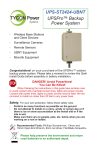
UPS-ST24 300W UBNT
UPSPro™ Backup
Power System
▫
Wireless Base Stations
▫
Surveillance Cameras
▫
Remote Gate Control
▫
Electric Fence
▫
Up to 192W loads
Congratulations! on your purchase of the UPSPro™ outdoor
backup power system. Please take a moment to review this Qwik
Install Guide before assembly or battery installation.
DANGER! Avoid Powerlines!
You Can Be Killed!
When following the instructions in this guide take extreme care
to avoid contact with overhead power lines, lights and power circuits.
Contact with power lines, lights or power circuits may be fatal. We recommend to install no closer than 20 feet to any power lines.
Safety: For your own protection, follow these safety rules.
▫
▫
▫
Perform as many functions as possible on the ground
Do not attempt to install on a rainy, windy or snowy day or if
there is ice or snow accumulation at the install site or if the
site is wet.
Make sure there are no people, pets, etc. below when you are
working on a roof or ladder.
Recommended Tools: Phillips Screwdriver, 13mm and
10mm Open End Wrench, 8mm nut driver, Flat Blade Screwdriv-
Please help preserve the environment and return
used batteries to an authorized depot
Qwik Install
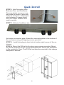
STEP 1: Add Grounding Wire
Between Door and Enclosure:
Remove plastic covers on copper studs on inside of door and
inside of enclosure. Add jumper
wire between 2 copper studs
and use copper washers and
nuts to secure.
STEP 2: Add wire feedthrus into
the bottom connector plate. Attach the connector plate to the bottom of
the enclosure using self tapping screws provided.
STEP 3: Install hole plug in drain hole in bottom right corner of the enclosure.
STEP 4: Mount the DIN rail to the door using screws provided. Mount
any extra equipment to the orange backplate and secure the backplate
in the enclosure. Note: The DIN rail can also be mounted to the orange
backplate if desired.
2
STEP 4: If pole mounting the enclosure, assemble the pole mount kit
to the back of the enclosure and
mount the enclosure to a pole using
the 6 hose clamps provided. The enclosure can also be wall mounted
using the 4 holes in the back of the
enclosure.
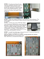
STEP 5: Insert the battery platform in the bottom of the enclosure. The
battery platform has cutouts so wires can be routed under the battery
as needed.
STEP 6: Attach the green DIN Rail adapters to the 8 port POE switch using the screws
provided. Clip the POE switch to the DIN rail.
Connect a cable from the controller LOAD
output to the 8 port POE switch green voltage
in connector V+ and V-. There are two V+
and two V– inputs. Either input is fine to use.
Just make sure polarity is correct.
STEP 7: Install the batteries in the enclosure. If using multiple batteries, connect in series for 24V output.
24V two battery and 24V four battery configurations are shown
below. Batteries are connected in series, with Plus(+) connected to Minus(-).
3
STEP 8: If batteries are installed on their side make
sure to apply an insulator to the top of the battery terminal to prevent the battery terminals from shorting to the
metal enclosure in case the battery shifts inside the enclosure during an earthquake.
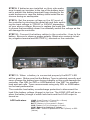
STEP 9: Set the proper voltage on the AC input of
the controller by removing the metal tab and then switching the input voltage to 120VAC or 240VAC depending
on your source voltage. Be sure to replace the metal tab
to ensure that somebody doesn’t accidentally switch the voltage as this
will damage the controller.
STEP 10: Connect the battery cables to the controller , then to the
battery. Be sure to observe proper polarity. Black wire connects to battery negative terminal and BATTERY(-) terminal on the controller.
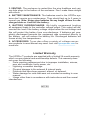
STEP 11: When a battery is connected properly the BATT LED
will be green. Make sure that the Battery Type is selected correctly and
never change the battery type during charging or this could damage the
controller. Use GEL for GEL or AGM batteries. Use WET for standard
lead acid wet cells. Tycon recommends using only GEL or AGM batteries for best performance.
The controller has battery overdischarge protection to disconnect the
load if the battery voltage (charge) is too low. The LOAD LED will be on
when the battery charge is within safe limits and the LOAD output is
turned on.
LED Indicators
LOAD (Load Power is Turned On = Green)
PWR (AC Power On = Yellow)
BATT ( Battery is Connected = Green)
CHD ( Battery is Fully Charged = Green)
CHG ( Battery is Charging = Yellow)
WET / GEL – Switch is positioned to WET(Green) or GEL
(Yellow)
4
STEP 12: Switch off controller and connect AC to the controller.
Be sure to follow local regulations for outdoor 120/240VAC connections.
STEP 13: Connect the load to the controller LOAD terminals. Be
sure to observe proper polarity. Switch on the controller to activate the
charging.
STEP 14: Plug or Tighten all wire feedthrus. If they don ’t tighten on
a small diameter wire, you can wrap some electrical tape around the
wire in the seal area to increase its diameter and make a better seal.
The enclosure needs some small amount of venting so be sure NOT to
seal all holes and feedthrus with silicon.
STEP 15: Make sure lid gasket is clean and free from any particles, then carefully close the cover, making sure that wires are clear of
the seam and hinge area. Use the special key to close the two cover
locks.
5
SPECIFICATIONS
Subject to change without notice
UPS-ST24-UBNT
Load Voltage (DC)
24V +/- 5%
Max Load Output
12A
Min Load Output
1A
2 battery 51Ah 1200VA
4 battery 102Ah 2400VA
Available Storage Capacities
Valve Regulated Sealed Lead Acid /
GEL
Battery Type
Battery Life
5 Years
WET Equalize = 28.8V, Float = 26.4V
GEL Equalize = 28.4V, Float = 27V
Charge Voltage
21.5V Load Off
25.2V Load On
Over-discharge protection
Self Consumption
POE Switch Output
<5.5W
7 POE Ports 24VDC @ 2A per port max
1 Uplink Port
10/100Mb IEEE802.3/802.3u Auto
Crossover
POE Switch
POE Protections
Over Temp, Over Current, Short, Over/
under voltage, Surge
VAC Input +/- 10%
Selector Switch 120VAC / 240VAC ,
50/60Hz
VAC Input Current
3.5A @ 115VAC / 1.8A @ 240VAC
Fuse
6A Internal Replaceable
Enclosure Type
Powder Coat Steel
Operating Temperature
-30°C to +60°C
TECH CORNER
Additional Information you may find useful
1. CONTROLLER: The controller turns off power to the load 21.5 and
reconnects when the battery reaches 25.2V. This protects battery from
overdischarge and increases battery life and performance. Note: The
load will turn on immediately as soon as AC power is restored.
2. CAPACITY: The UPSPro™ UPS-ST24 is rated at 192W load output. It can deliver 288W to the load but then the power available for battery charging is too small, so we recommend not to exceed 192W to the
load for best performance.
6
3. VENTING: The enclosure is vented thru the wire feedthrus and various hole plugs in the bottom of the enclosure. Don’t make these airtight
with silicon
4. BATTERY MAINTENANCE: The batteries used in the UPSPro systems don’t require any maintenance. They should last up to 5 years in
normal use. Note: Never store batteries for any length of time in a discharged state or it will kill the battery.
5. BATTERY OVERDISCHARGE: We highly recommend hooking
all equipment loads to the controller voltage output. This output will disconnect the load if the battery voltage drops below the set voltage and
this will protect the battery from over-discharge. If batteries get completely discharged because the equipment was connected directly to
the battery, you will reduce the battery life. Discharged batteries will
freeze at very low temperatures.
6. ACCESSORIES: Tycon also offers a variety of voltage conversion products to meet almost any need. Just visit tyconpower.com for
more info.
Limited Warranty
The UPSPro™ products are supplied with a limited 24 month warranty
which covers material and workmanship defects. This warranty does
not cover the following:
▫ Parts requiring replacement due to improper installation, misuse,
poor site conditions, faulty power, etc.
▫ Lightning or weather damage.
▫ Physical damage to the external & internal parts.
▫ Products that have been opened, altered, or defaced.
▫ Water damage for units that were not mounted according to user
manual.
▫ Usage other than in accordance with instructions and the normal
intended use.
NOTES
7
8000027 Rev 1 UPS-ST24 300W UBNT UPSPro™ Qwik Install Guide
8