Transcript
PYLE
www.pyleaudio.com
DIGITAL
TACHOMETER
MODEL: PST43
OPERATION
MANUAL
Your purchase of this DIGITAL TACHOMETER marks a
step forward for you in the field of precision measurement.
Although, this LASER TACHOMETER is a complex and
delicate instrument, its ruggedness will allow many years of
use if proper operating techniques are developed. Please
read the following instructions carefully and always keep
this manual within easy reach.
WARNING!
TO AVOID INHURIES TO ANIMAL OR HUMAN EYES,
PLEASE DO NOT POINT THE LASER BEAM IN EYES OR
LOOK DIRECTLY INTO BEAM.
1. FEATURES
* Wide measuring range from 5 to 100,000 RPM
* 0.1 RPM resolution for the measured value from 5 to 999
RPM.
* The last value/max and value/min value will be stored into
the memory automatically and can be obtained by pressing
memory call button.
* LCD display gives exact RPM reading with no guessing or
errors. Low battery consumption.
* This tachometer uses the exclusive chip, Micro-computer
LST circuit & crystal time base, which offers highly accurate
measurements and fast sampling time.
* The use of durable, long-lasting components including a
strong, light weight ABS-plastic housing that assures
maintenance free performance for many years.
*The housing cabinet has been carefully shaped to fit
comfortably in either hand.
2. SPECIFICATIONS
DISPLAY 5 digits, 10mm (0.4") LCD
Measurement & Range 5 to 99,999RPM
Accuracy (73.4 +
0.1RPM (<1000RPM) 1RPM (=1000RPM)
41)
Time base quartz crystal: 4194MHZ
Circuit exclusive chip: micro-computer LSI circuit
Operating temp. 0-50°C (32-122)
Operating humidity less than 80%R.H
Memory last, maximum, minimum value
Battery 4*1.5V AA (UM-3) battery
Power consumption approx. 153mA DC
Size 190*72*37mm (7.5*2.8*1.5inch)
Weight 235g (0.521bs) / including batteries
carrying case ............... 1 piece
Accessories included reflecting tape marks(600m) ............ 1 piece
Operation manual ............... 1piece
3. FRONT PANEL DESCRIPTION
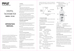
Fig 1
3-1 Reflective mark 3-2 Photo Signal light beam
3-3 Target indicator 3-4 Display
3-5 Operation Button 3-6 Memory call button
3-7 Battery Compartment/Cover
4. MEASURING PROCEDURE
Apply a reflecting mark to the object being measured.
Depress the “Operation button” (3-5 Fig 1) and align the
visible “photo signal Light beam” (3-2 fig1) with the applied
target. Verify that the “Target indicator” (3-3 fig 1) lights when
the target passes through the light beam. Release the
“operation button” when the reading stabilizes (about 2
seconds).
Consideration:
If measuring very low RPM values, attach more
‘REFLECTIVE MARKS” evenly spaced apart from each other.
Then divide the reading shown by the number of
“REFLECTIVE MARKS” to get the real RPM.
5. MEMORY CALL BUTTON OPERATION
1) The minimum, maximum and the last (final) readings are
automatically stored during measurement. These values can
be recalled anytime by pressing the “Memory call button” (3-6
fig1 ).
A Max value
Display Last value
readin :
9 Min value
У
Measuring time
Fig. 2
2) To recall the stored value, follow these procedures:
Release the “operation button” (3-5 fig 1) first.
a) Press the “memory call button” (3-6 fig1) once to display
the last reading. The symbol “LA” will appear on the display.
b) Press the “memory call button”(3-6 fig1) once again to
display the maximum value. The symbol “UP” will appear on
the display.
c) Press the “memory call button”(3-6 fig1) once more to
display the maximum value. The symbol “DN” will appear on
the display.
6. BATTERY REPLACEMENT
1) When “LO” appears on the LCD display, it indicates a
battery output of approximately less than 4.5v. ltis
recommended to replace the battery; however in-spec
measurement may still be made for several hours after low
battery indicator appears before the instrument becomes
inaccurate.
2) Open the “battery cover” (3-7 Fig. 1). Inside the battery
compartment, replace with new batteries and reinstate the
cover.