1
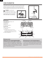
Instruction Manual
Bedienungsanleitung
Manuel d’utilisation
Manuale di istruzioni
EN
NOTICE
All instructions, warranties and other collateral documents are subject to change at the sole discretion of Horizon Hobby, Inc.
For up-to-date product literature, visit horizonhobby.com and click on the support tab for this product.
Meaning of Special Language
The following terms are used throughout the product literature to indicate various levels of potential harm when operating this
product:
NOTICE: Procedures, which if not properly followed, create a possibility of physical property damage AND a little or no possibility
of injury.
CAUTION: Procedures, which if not properly followed, create the probability of physical property damage AND a possibility of
serious injury.
WARNING: Procedures, which if not properly followed, create the probability of property damage, collateral damage, and serious
injury OR create a high probability of superficial injury.
WARNING: Read the ENTIRE instruction manual to become familiar with the features of the product before operating.
Failure to operate the product correctly can result in damage to the product, personal property and cause serious injury.
This is a sophisticated hobby product. It must be operated with caution and common sense and requires some basic mechanical
ability. Failure to operate this Product in a safe and responsible manner could result in injury or damage to the product or other
property. This product is not intended for use by children without direct adult supervision. Do not attempt disassembly, use with
incompatible components or augment product in any way without the approval of Horizon Hobby, Inc. This manual contains instructions for safety, operation and maintenance. It is essential to read and follow all the instructions and warnings in the manual, prior to
assembly, setup or use, in order to operate correctly and avoid damage or serious injury.
WARNING AGAINST COUNTERFEIT PRODUCTS
Thank you for purchasing a genuine Spektrum product. Always purchase from a Horizon Hobby, Inc. authorized dealer
to ensure authentic high-quality Spektrum product. Horizon Hobby, Inc. disclaims all support and warranty with regards,
but not limited to, compatibility and performance of counterfeit products or products claiming compatibility with DSM2 or
Spektrum.
WARRANTY REGISTRATION
Visit www.spektrumrc.com/registration today to register your product.
GENERAL NOTES
• Radio controlled models provide pleasurable skill challenges
and opportunity for increasing mastery of piloting.
• Models are hazardous when operated and maintained incorrectly.
• Always install and operate a radio control system correctly.
• Always pilot a model so the model is kept under control in
all conditions.
• Please seek help from an experienced pilot or your local
hobby store.
• Contact local or regional modeling organizations for guidance and instructions about flying in your area.
• When working with a model, always power on transmitter
first and power off the transmitter last.
• After a model is bound to a transmitter and the model is set
up in the transmitter, always bind the model to the transmitter again to establish failsafe settings.
2
PILOT SAFETY
• Always make sure batteries are fully charged before flying.
• Time flights so you fly safely and under control.
• Do a range check of the transmitter and the model before
flying a model.
• Make sure control surfaces correctly respond to transmitter
control before flying.
• Do NOT fly a model near spectators, parking areas or any
other area that could result in injury to people or damage to
property.
• Do NOT fly during adverse weather conditions. Poor visibility
can cause pilot disorientation and loss of control of a model.
Wind can cause loss of control and damage to a model.
Moisture and ice can damage a model.
• Do NOT point transmitter antenna directly at a model.
The signal coming from the tip of the antenna is weak by
comparison to the signal coming from other parts of the
antenna.
• When a flying model does not respond correctly to controls
(moving erratically or abnormally) land the model and correct the cause of the problem.
SPEKTRUM DX6i • RADIO INSTRUCTION MANUAL
EN
TABLE OF CONTENTS
DSMX..........................................................................4
Transmitter Functions
Charging Batteries...............................................6
Install Batteries....................................................6
Binding........................................................................7
Using transmitter.........................................................8
Antenna.......................................................................8
Main Screen................................................................8
Warning screens..........................................................8
Programming Guide
SETUP LIST .........................................................9
ADJUST LIST........................................................9
Function Options Not Shared..............................10
MODEL TYPE .....................................................11
MODEL NAME....................................................11
MONITOR...........................................................11
REVERSE............................................................11
THRO CUT..........................................................11
WING TAIL MIX...................................................12
SWASH TYPE .....................................................12
D/R COMBI (Dual Rate Combination)..................12
TIMER................................................................13
RANGE CHECK....................................................13
POWER SETTING................................................13
MODULATION TYPE.............................................13
MODEL SELECT..................................................14
D/R & EXPO (Dual Rate & Expo)..........................14
CONTRAST.........................................................14
COPY/RESET......................................................14
TRAVEL ADJ (Travel Adjust).................................15
SUB-TRIM..........................................................15
FLAPS ...............................................................15
SPEKTRUM DX6i • RADIO INSTRUCTION MANUAL
GYRO.................................................................15
THRO CUR (Throttle Curve) ................................16
PITC CUR (Pitch Curve).......................................16
SWASH MIX........................................................17
MIX 1 or MIX 2...................................................17
DIFFERENTIAL....................................................18
REVO MIX (Revolution Mix).................................18
Master/Slave Information
To operate the DX6i as a master:........................18
To operate the DX6i as a slave:...........................18
Failsafe......................................................................19
Receiver and servo information
Receiver Installation...........................................19
Servo Installation................................................20
Servo Precautions..............................................20
Power System Requirements.....................................20
Recommended Power System Guidelines..................20
Troubleshooting Guide...............................................21
AMA National Model Aircraft Safety Code...................21
FCC Information.........................................................22
FAA Information.........................................................22
Parts list....................................................................22
Warranty and Repair Policy........................................23
Parts Contact Information..........................................24
Compliance Information for the European Union.........24
Appendix
Control Stick Length Adjustment.........................25
Control Stick Tension Adjustment........................25
Throttle Stick Ratchet Strip Installation...............25
Servo Control.....................................................26
3
EN
DSMX
Spektrum launched the 2.4GHz RC revolution with its DSM2
technology. Since then millions of hobbyists the world over have
come to embrace 2.4 as the way to fly. Spektrum leads the way
yet again with DSMX; the world’s first wideband, frequency-agile
2.4GHz signal protocol.
How Does DSMX Work?
It’s a crowded 2.4GHz world out there and every 2.4GHz system
faces the same challenges. DSMX better equips you for these
challenges by combining the superior data capacity and interference resistance of a wideband signal (like that used in DSM2)
with the agility of frequency shifts.
Compared to the wideband signal of DSMX, the narrow band
signal of other frequency hopping 2.4 transmitters is more likely
to suffer data loss in the event of on-channel interference. Think
of it as a river vs. a stream. It takes more interference to dam a
river than it does a stream.
As more and more 2.4 transmitters vie for the same number
of available channels, there is more interference and more of a
risk for data loss. By adding the agility of frequency shifts to the
superior interference resistance of a wideband signal, DSMX
is far less likely to suffer significant data loss from on-channel
interference. The result is quicker connection times and superior
response in even the most crowded 2.4GHz environment.
NOTICE: While DSMX allows you to use more than 40 transmitters simultaneously, when using DSM2 receivers, DSMX receivers in DSM2 mode or transmitters in DSM2 mode, do not use
more than 40 transmitters simultaneously.
DSMX Operational Differences
DSMX transmitters and receivers function nearly identically to
Spektrum DSM2 systems. Binding, setting the failsafe, recording
flight log data, as well as general use of the system is no different than using any current Spektrum system.
Following are the operational differences:
Brownout Detection- Not Available on DSMX Receivers,
DSM2 receivers feature Brownout Detection that flashes the
receiver’s LED if a power interruption occurs. While DSMX
receivers have QuickConnect™ and recover instantly from a
power interruption, the architecture of DSMX prevents Brownout
Detection when operating in DSMX mode.
4
Flight Log Recording- Fades Higher than DSM2
Note that DSMX hops through the band while DSM2 finds two
quiet channels and remains on those channels. Consequently
because DSMX operates on quiet and noisy channels, it’s common to have more Antenna Fades than when using DSM2, when
used in busy 2.4GHz environments. When taking flight log data
readings, the Frames and Hold Data are important and should be
used a reference while Fades are insignificant due to the nature
of frequency hopping. A 10-minute flight will typically result in
less than 50 Frame Losses and no Holds.
Just How Good is DSMX?
In multiple tests, 100 DSMX systems were operated simultaneously for extended periods of time. During these tests each of the
100 systems was monitored in flight and on the ground. In every
test not a single case of RF link loss, latency increase or control
degradation was experienced or recorded.
Is DSMX Compatible with DSM2?
Yes. DSMX is fully compatible with all DSM2 hardware. In fact,
many pilots may find the DSM2 equipment they have now is all
they will ever need. Even if a new DSMX transmitter eventually
comes along that they really want, all the DSM2 receivers they
have now will work with it.
It is important to note, however, that while DSMX is compatible
with DSM2, the only way to experience the full benefits of DSMX
in a busy 2.4 environment is by pairing a DSMX transmitter with
a DSMX receiver.
Can DSM2 Transmitters be Upgraded to DSMX?
Yes. DX8 owners can simply download Spektrum AirWare™ v2.0
software from spektrumrc.com and update the firmware using
their SD card. DX6i transmitters manufactured after October
2010 can be upgraded using instructions provided on spektrumrc.com. All other DX6i DSM2 transmitters can be upgraded for
$75 by sending them to the Horizon Hobby service center. DSM2
receivers and transmitter modules cannot be upgraded to DSMX.
Does DSMX have ModelMatch and ServoSync?
Yes. DSMX will provide you with these and other exclusive Spektrum advantages you already enjoy with DSM2.
Want to know more about DSMX? Visit spektrumrc.com for complete details on this as well as the many other reasons Spektrum
is the leader in 2.4.
SPEKTRUM DX6i • RADIO INSTRUCTION MANUAL
EN
TRANSMITTER FUNCTIONS
Press
Function
A
Antenna
B
Function
K
Charge Port
Throttle Cut
L
Rudder Trim
C
Mix/Throttle Hold (Mode 2)
Trainer/Bind (Mode 1)
M
Throttle Trim (Mode 2)
Elevator Trim (Mode 1)
D
Rudder Dual Rate (Mode 2)
Gear/Flight Mode (Mode 1)
N
Throttle/Rudder Stick (Mode 2)
Elevator/Rudder Stick (Mode 1)
E
Aileron Dual Rate
O
Elevator Dual Rate
F
Aileron/Elevator Stick (Mode 2)
Aileron/Throttle Stick (Mode 1)
P
Gear/Flight Mode (Mode 2)
Rudder Dual Rate (Mode 1)
G
Elevator Trim (Mode 2)
Throttle Trim (Mode 1)
Q
Trainer/Bind (Mode 2)
Mix/Throttle Hold (Mode 1)
H
Aileron Trim
R
Flap/Gyro
I
Roller
S
Trainer Port
J
On/Off Switch
T
Battery Cover
3 seconds
Cursor
S
T
A
Do not try to change transmitter from one mode to another.
Instead, send transmitter to the appropriate product support
office for mode change.
R
B
Q
C
P
D
O
E
N
F
G
M
H
L
K
I
J
Note: The transmitter comes with a thin clear plastic film
applied to some front panels for protection during shipping.
Humidity and use may cause this film to come off
Carefully remove this film as desired.
SPEKTRUM DX6i • RADIO INSTRUCTION MANUAL
5
EN
TRANSMITTER BATTERIES
1.
2.
Install Batteries
This transmitter requires 4 AA batteries. Transmitters are sold
with and without batteries and a Spektrum charger.
3.
1.Remove battery cover from the back of the transmitter.
2.Install batteries as shown where batteries fit.
3.Install battery cover.
Failure to exercise caution while using this product and comply with the following warnings could result in
product malfunction, electrical issues, excessive heat, FIRE, and ultimately injury and property damage.
• Read all safety precautions and literature prior to use of this
product
• Never allow minors to charge battery packs
• Never drop charger or batteries
• Never attempt to charge damaged batteries
• Never attempt to charge a battery pack containing different
types of batteries
• Never charge a battery if the cable has been pinched or
shorted
• Never allow batteries or battery packs to come into contact
with moisture at any time
• Never charge batteries in extremely hot or cold places (recommended between 50–80 degrees F or 10–27 degrees C)
or place in direct sunlight
Charging Batteries
Rechargeable batteries can be recharged in the transmitter
using a 4.8-volt Spektrum charger. Improved battery reliability
requires a full charge for initial use. While the transmitter is
powered off, connect the transmitter charge port to the charger.
Charging must be done in a safe place NOT affected by the
usual heat that comes from a charger and batteries during
charging.
CAUTION: Use ONLY the 150mAh center pin negative
Spektrum adaptor (SPM9550) with your transmitter.
Note: The 4.8-volt charger recharges at a rate of 150mAh per
hour, so 4 1.2V 1500mAh batteries require approximately 10
hours for an initial charge.
CAUTION: Charge only rechargeable batteries. Non-rechargeable batteries may burst causing injury to persons
and/or damage to property.
6
• Always disconnect the battery after charging, and let the
charger cool between charges
• Always inspect a new battery before charging
• Always terminate all processes and contact Horizon Hobby
if the product malfunctions
• Always keep batteries and charger away from any material
that could be affected by heat (such as ceramic and tile), as
they can get hot
• Always end the charging process if the charger or battery
becomes hot to the touch or starts to change form (swell)
during the charge process
Charger Pigtail for Transmitter
BLACK TO POSITIVE
BLACK W/WHITE STRIPE TO NEGATIVE
Spektrum Transmitter Charge Jack Polarity
-
+
Charger power outlet
terminals not shown.
SPEKTRUM DX6i • RADIO INSTRUCTION MANUAL
EN
BINDING
You must bind the receiver to the transmitter before it will operate. Binding is sharing identification codes between the receiver and
the active memory of the transmitter. Once bound, the receiver only connects to the transmitter when the previously bound model
memory is selected. You will need to rebind after the model is set in the transmitter to fully program the model’s failsafe positions. If
another model memory is selected, the receiver will not connect. This feature is called ModelMatch™ and prevents flying a model
using the wrong model memory.
1.
2.
3.
Binding using receiver and receiver battery
1.
2.
5.
4. HOLD SWITCH WHILE POWERING ON
4. HOLD SWITCH WHILE POWERING ON
3.
6.
5.
6.
Mode 2 Shown
Mode 2 Shown
1. Lower throttle to lowest position and make sure the
transmitter is powered off
2. Insert bind plug into BATT/BIND (BIND/DATA) receptacle.
3. Insert receiver battery into ANY open receptacle.
Note: The receiver’s LED flashes when the receiver is ready to
bind.
4. While holding Trainer/Bind switch, power on transmitter.
5. Keep hold on trainer switch until receiver’s LED stays
illuminated; this indicates the receiver is bound to the
transmitter.
6. Remove bind plug from receiver.
Binding using receiver and ESC
1.
1.
2.
4.
4.
2.
3.
3.
5. HOLD SWITCH WHILE POWERING ON
5. HOLD SWITCH WHILE POWERING ON
6.
6.
7.
7.
Mode 2 Shown
1. Lower throttle to lowest position and make sure the
Mode 2 Shown
transmitter is powered off
2. Insert bind plug into BATT/BIND (BIND/DATA) receptacle.
3. Insert ESC plug into THRO receptacle.
4. Connect battery to ESC and turn on ESC switch, if available.
Note: The receiver’s LED flashes when the receiver is ready to
bind.
SPEKTRUM DX6i • RADIO INSTRUCTION MANUAL
5. While holding Trainer/Bind switch, power on transmitter.
6. Keep hold on trainer switch until receiver’s LED stays
illuminated; this indicates the receiver is bound to the
transmitter.
7. Remove bind plug from receiver.
7
EN
USING TRANSMITTER
Antenna
The transmitter antenna bends and turns at the hinge (A) and only bends
and turns to the front of the transmitter. The antenna cannot point to the
back of the transmitter. Turn antenna tip to point away from the model
and ground. Signals transmit strongest from the antenna shaft, not the tip.
WARNING: Do not pick up the
transmitter by the antenna. Do not
alter or put weight on the antenna. Damage
to antenna parts can decrease transmitter
signal strength, which can result in loss of
model control, injury or property damage.
A
Main Screen
A Transmitter Battery Charge Level
B Model Memory
C Model Name
D Model Type
E Elevator Trim (Mode 2)
F Time Count
G Aileron Trim
H Time Count Direction
I Rudder Trim
J Transmitter Battery Charge Amount
(an alarm sounds and the screen flashes
when battery charge gets down to 4.1V.)
K Throttle Trim (Mode 2)
K
E
I
G
B
A
D
MDL6 MUSTANG
5.0V
K
J
C
I
H
DN06:00
G
E
F
Warning screens
Warning Screen for Throttle Hold/Stunt Mode
If the Model Type is HELI and the F MODE or TH HOLD switch
are in the 1 position when the transmitter is powered on, the
alarm will sound. When the F MODE switch or THROTTLE HOLD
switch are on, an alarm sounds and warning shows on the LCD
screen. When all switches are moved to position 0, the display
returns to normal and the alarm stops.
8
Warning Screen for Low Transmitter Batteries
When the transmitter is powered on with low battery power (at
4.1-volts or less), a warning sounds and the screen flashes with
text to prevent use of the transmitter with low batteries. Power
off the transmitter and replace batteries to stop the sound and
flashing screen.
SPEKTRUM DX6i • RADIO INSTRUCTION MANUAL
EN
PROGRAMMING GUIDE
This manual describes airplane and helicopter software functions. Some functions enable other functions. For example
within Model Type in the Setup list, you can choose between
Model Type ACRO and Model Type HELI. These then enable
the programming functions that follow Model Type according
to the model type you choose.
NAVIGATION
Press
Press
Turn
Move between options or
change value in an option
Enter, Choose or
Exit
ADJUST LIST screen shows when roller is pressed after transmitter is powered on.
SETUP LIST screen shows when roller is held down, transmitter is powered on, then roller is released. This list contains
programming functions normally used only in initial setup of a
model, such as MODEL TYPE, REVERSE and MODEL NAME.
To access the SETUP LIST from the Main Screen, press and hold
roller for more than 3 seconds. Release roller so SETUP LIST
shows.
Hold
Press
Hold for 3 seconds and release
to move to a higher screen
MAIN SCREEN shows when transmitter is powered on. This
screen shows active model memory MDL1 to MDL10 (these
can be ACRO and/or HELI models). This includes settings for the
model trim, battery charge (right of throttle, above rudder) and
timer choice (DN or UP) and the time limit.
SETUP LIST
This screen is for access to setup of model control, depending
on the Model Type of the active model memory.
B
SETUP LIST
A
C
Main
1
MODEL TYPE
D
A Function name
B Screen title
C Navigation help: Next higher screen
D Function #
A
ACRO
HELI
MODEL TYPEHELI
1
MODEL NAME
2
MODEL
TYPE
MONITOR
31
MODEL
NAME
REVERSE
42
MONITOR
SWASH
TYPE
53
REVERSE
THRO
CUT
64
SWASH
TYPE
D/R
COMBI
75
THRO
CUT
TIMER
86
D/R COMBI
RANGE
CHECK
97
TIMERSETTING
8
POWER
10
RANGE CHECKTYPE 11
9
MODULATION
POWER
SETTING
10
CONTRAST
12
MODULATION TYPE 13
11
COPY/RESET
CONTRAST
12
ADJUST
LIST
14
COPY/RESET
13
ADJUST LIST
14
MODEL TYPEACRO
1
MODEL NAME
2
MODEL
TYPE
MONITOR
31
MODEL
NAME
REVERSE
42
MONITOR
THRO
CUT
53
REVERSE
WING
TAIL MIX
64
THRO
CUT
D/R
COMBI
75
WING
TAIL
MIX
TIMER
86
D/R COMBI
RANGE
CHECK
97
TIMERSETTING
8
POWER
10
RANGE CHECKTYPE 11
9
MODULATION
POWER
SETTING
10
CONTRAST
12
MODULATION TYPE 13
11
COPY/RESET
CONTRAST
12
ADJUST
LIST
14
COPY/RESET
13
ADJUST LIST
14
ADJUST LIST
This screen is for access to functions that adjust control,
depending on the Model Type of the active model memory.
B
ADJUST LIST
A
C
Main
MODEL SELECT
1
D
ACRO
ACRO
MODEL SELECT
D/R&EXPO
MODEL ADJ
SELECT
TRAVEL
D/R&EXPO
SUB
TRIM
TRAVEL
FLAPS ADJ
SUB1TRIM
MIX
FLAPS
MIX
2
MIX 1
DIFFERNTIAL
MIX
SETUP2 LIST
DIFFERNTIAL
SETUP LIST
A
1
2
31
42
53
64
75
86
97
8
9
HELI
HELI
MODEL SELECT
D/R&EXPO
MODEL
SELECT
TRAVEL ADJ
D/R&EXPO
SUB
TRIM
TRAVEL ADJ
GYRO
SUB TRIM
THRO
CUR
GYROCUR
PITC
THRO
SWASH CUR
MIX
PITC
MIX
1 CUR
SWASH
MIX
2 MIX
MIX 1MIX
REVO
MIX 2 LIST
SETUP
REVO MIX
SETUP LIST
1
2
31
42
53
64
75
86
97
8
10
9
11
10
12
11
12
A Function name
B Screen title
C Navigation help: Next higher screen
D Function #
SPEKTRUM DX6i • RADIO INSTRUCTION MANUAL
9
EN
FUNCTION OPTIONS NOT SHARED BY THE MODEL TYPES
Acro
Inhibit
Activate
MODEL TYPE
REVERSE
THRO-N
ELEV-N
GEAR-N
DUALAILE
List
AILE-N
RUDD-N
FLAP-N
DUALAILE
WING TAIL MIX
TRAVEL ADJ
DIFFERNTIAL
DIFFERNTIAL
List
0%
0
0
0
List
AILE
RUDD
FLAP
0
0
0
FLAPS
List
THRO 100% AILE 100%
ELEV 100% RUDD 100%
GEAR 100% FLAP 100%
DUALAILE RATE
SUB TRIM
THRO
ELEV
GEAR
MIX 1
List
DIFFRNTIAL
INHIBIT
MIX 2
Heli
MODEL TYPE
REVERSE
THRO-N
ELEV-N
GYRO-N
CCPM 120°
List
GYRO
AILE-N
RUDD-N
PITC-N
GYRO
1SERVO90°
SWASH TYPE
THRO CUR
PITC CUR
SWASH MIX
AILE
ELEV
PITCH
- 75%
- 75%
+ 85%
List
SWASH MIX
List
SWASH MIX
INHIBIT
GYRO
List
INH
GYRO
List
RATE
SW-F.MODE
0: 50.0%
1: 50.0%
MIX 1
TRAVEL ADJ
List
THRO 100% AILE 100%
ELEV 100% RUDD 100%
GYRO 100% PITC 100%
SUB TRIM
THRO
ELEV
GYRO
10
GYRO
0
0
0
MIX 2
List
AILE
RUDD
PITC
0
0
0
REVO MIX
SPEKTRUM DX6i • RADIO INSTRUCTION MANUAL
EN
MODEL TYPE
This transmitter supports 2 model types: Airplane
(ACRO) and Helicopter (HELI). Model Type is stored
in a model memory.
MODEL TYPE
MDL6 MUSTANG
5.0V
List
DN06:00
CAUTION: When Model Type is changed, programming
for a model memory is erased and returned to factory
default settings.
A Options affecting other screens and Functions
ACRO
HELI
A
MODEL NAME
A
Model Name function assigns a name to a specific
MDL6 MUSTANG
memory, so the model memory is easier to identify.
5.0V DN06:00
The model memory number and a name is displayed
on the Main screen. The name fills 8 character
spaces chosen from spaces, symbols, numbers and letters.
MODEL NAME
List
MODEL 6
MUSTANG
A Active model memory number (1–10)
B Model name you designate
B
MONITOR
THRO
THR
2 Aileron
AILE
AILE
AIL
3 Elevator
ELEV
ELEV
ELE
4 Rudder
RUDD
RUDD
RUD
5
GEAR
GYRO
CH5
6
FLAP
PITC
AUX
THROTTLE ALT prevents throttle trim from altering the
throttle position above half throttle. You can adjust trim
within the lower half of the throttle control range.THROTTLE
ALT keeps a throttle servo from being overdriven on the high
end of its control range.
REVERSE
Reverse function changes servo throw direction for all 6
channels. Movement of a control stick or switch is NOT
changed. Instead, a channel’s response to transmitter input
is reversed.
Note: Your aircraft manual may refer to this as changing
transmitter flight control directions in the Control Test/Reverse Controls section.
A Channels
B Servo direction N=normal, R=reverse
C This is PITC on HELI type, FLAP on ACRO type
D This is GYRO on HELI type, GEAR on ACRO type
THR
AIL
ELE
RUD
CH5
AUX
[
[
MONITOR
◊
THRO
◊
1 Throttle
A
◊
MONITOR
SCREEN
◊
HELI
◊
A Stick or switch position (within programmed settings:
CCPM swash mix is shown here)
B Center position on marker line.
ACRO
CHANNEL
List
]
]
◊
The Monitor functions shows channel movement and direction
when controls are moved. Throttle (THR), aileron (AIL), elevator
(ELE), rudder (RUD), channel 5 (CH5) and auxiliary (AUX)
show as arrows on a line.
B
B
REVERSE
A
THRO-N
ELEV-N
GEAR-N
List
A
AILE-N
RUDD-N
FLAP-N
C
D
THRO CUT
Thro Cut function activates (ACT) or inhibits (INH) the Throttle
Cut button. When an activated Throttle Cut button is pressed, the
throttle moves to the low throttle, low trim position for safe and
convenient shut down of the engine or removal of power to the
electric motor.
THRO CUT
List
A
POSITION - ACT
A Option (ACT or INH)
SPEKTRUM DX6i • RADIO INSTRUCTION MANUAL
11
EN
WING TAIL MIX
Wing Tail Mix function supports Normal, Dual Aileron, V-Tail and
Elevon (Delta) mixing. Refer to your model’s manual for recommended settings. See Appendix for information about recommended wing type servo installations on scratch built models.
Normal
This normal or default setting for airplanes is 1 servo channel
for aileron, 1 channel for elevator and 1 channel for the rudder.
These common wing and tail functions are enabled when you
set DUALAILE, ELEVON and V-TAIL at INH (inhibit).
Elevator stick input causes movement of the surfaces together
for up/down movement and pitch control. Aileron stick control
input causes movement of the surfaces in opposite directions
for roll control. Connect one tail servo to (ELE) and the other tail
servo to (AILE) in the receiver. Use individual functions such as
servo reversing, sub-trims, etc. for each servo to achieve correct
control surface movement. Use sub-trims for separate neutral
adjustments. Use dual rate function so you can independently
adjust elevator-versus-rudder travel.
WINGTAILMIX
Dual Aileron Wing Type Selection
Dual Aileron requires use of a servo for each aileron and supports use of ailerons as flaps or spoilers. This function also
supports precise independent adjustment of up and down travel,
and independent sub-trim and differential for each aileron.
DUALAILE INH
V-TAIL
INH
ELEVON
INH
V-tail Selection
V-tail combines the elevator and rudder channels for pitch and
yaw control when using a V-tail equipped airplane. This function
also supports precise independent adjustment of up and down
travel, and independent sub-trim and dual rate adjustments for
V-tail control surfaces.
Elevon Wing Type Selection
Elevon (Delta) wing combines aileron and elevator functions for
precise control of roll and pitch.
Note: Delta or Elevon Mixing is for flying-wing airplanes and
uses 2 servos in the wing to control 2 trailing edge-control
surfaces for pitch and roll control.
D
A Helicopter swashplate configuration
B Choice of this type enables SWASH MIX
A
B
C
A DUALAILE and V-TAIL can be ACT at the same time
B Options (INH or ACT)
C When ELEVON is ACT, DUALAILE and V-TAIL become INH
D When DUALAILE is ACT, you can adjust the DIFFRNTIAL
function value.
Note: When Flaperon or Delta Wing type is chosen, travel
adjustment is used to adjust individual servo throw, while combined aileron travel is adjusted with the aileron dual rate. You
can also adjust aileron differential. Reverse switches are
applicable for each servo. Make neutral adjustments on each
servo using the SUB TRIM function.
SWASH TYPE
Swash Type function supports 1 Servo: 90 degrees (standard
mechanical mix) and 3 Servo: CCPM 120 degrees.
Refer to your model’s manual for recommended settings.
Note: Choosing CCPM 120 enables SWASH MIX function.
List
SWASH TYPE
A
List
1SERVO90°
B
SWASH TYPE
List
CCPM 120°
D/R COMBI (Dual Rate Combination)
The Dual Rate Combi function allows you to assign a switch
for combining D/R&EXPO. You can assign aileron, elevator and
rudder dual rate and exponential functions to 1 of 3 common
switches so dual rates/expo for all 3 channels is enabled by one
switch.
D/R COMBI
D/R SW:
List
A
INH
A Options (INH, AILE, ELEV or RUDD switches.
GEAR switch can be used in HELI mode.)
12
SPEKTRUM DX6i • RADIO INSTRUCTION MANUAL
EN
TIMER
B
The Timer function includes a timer on the Main
MDL6 MUSTANG
screen and an audible alarm. When the time
List
TIMER
5.0V DN06:00
expires, 5 beeps sound every 5 seconds.
C
A
Timer DOWN – This sets a countdown (from up
MDL6 MUSTANG
DOWN TIMER-06:00
to 59 minutes and 50 seconds).
SWITCH---TRAINER
Timer UP – This sets a count-up timer (up to 59 minutes and 50
seconds). The start time is programmable. The default start of
D
00:00 is recommended.
When the Timer function is enabled, the timer displays on the
A Timer direction (DOWN or UP) displays on Main screen
Main screen.
B Model memory number and name
You can assign the Trainer Switch, Power On or Throttle Cut
C Optional value (Time Limit DOWN can be 59:50 to 0:00 and
button to stop, start and reset the timer.
UP can be 0:00 to 59:50 that displays on Main screen)
Note: Reset the timer by holding the assigned starter for more
D Timer start switch (TRAINER, THRO CUT or INH)
than 3 seconds.
Note: Timer UP count is helpful for recording sailplane flight
time. Timer DOWN count is helpful for setting an alarm for landing a powered model before receiver power fully discharges.
RANGE CHECK
Range Check function activates or inhibits use of the Trainer
switch to do a Range Check (which decreases transmitter output
power).
A Trainer/Range Check switch position (When switch is held,
ACT shows here)
1. Move the transmitter no less than 30 paces, approximately
90 feet (27m), from the model.
2. Face the model with the transmitter held in normal flying
position.
3. Activate Range Check in the transmitter screen.
4. Pull and hold the trainer switch on the top left side of the
transmitter (Mode 2) or on the top right side (Mode 1). This
causes reduced power output from the transmitter.
5. Model should respond to all transmitter control inputs while
the trainer switch is held.
POWER SETTING
The Power Setting function adjusts transmitter power output to
conform to national standards.
Note: EU 328 is appropriate for most European countries
conforming to EU 300-328, while US 247 is for use in the
United States and countries outside the European Union (EU).The
France setting is for use in France.
NOTICE: The DX6i has a France RF setting that complies with
French regulations. Always use the France power setting when
operating the transmitter outdoors in France.
MODULATION TYPE
The Modulation Type function allows you to assign a DSM modulation type (DSM2 or DSMX) to your transmitter.
Note: There is no option to return to list. You must choose a
modulation type in order to return to the menu
A Option value (DSM2 or DSMX)
SPEKTRUM DX6i • RADIO INSTRUCTION MANUAL
RANGE CHECK
CHECK
List
A
INH
6. If control issues exist, refer to your model’s manual for
troubleshooting guidance. When needed, contact the
appropriate Horizon Product Support office.
Advanced Range Testing
An advanced range test using a Flight Log (SPM9540) is recommended for models built with a large amount of conductive
material and a receiver with a data port. Refer to the Flight Log
instructions for information about Range Testing.
POWER SETTING
List
A-EU 328
MODULATION TYPE
AUTO DSM-X ENABLE
DSMX AND DSM-2
STANDARD RECEIVERS.
A
13
EN
CONTRAST
CONTRAST
A
The Contrast function adjusts the image on the LCD for visibility
in sunlight. The default value is 50%.
A Option value (0-100%)
50%
COPY/RESET
The Copy/Reset function supports copying the active model memory A
to any of the other 9 available model memories. This is useful for
setting up a model with different programming or to set up a similar
model.
B
COPY/RESET
List
MODEL 6 MUSTANG
COPY TO 1
SURE? NO/YES
A1Option value (1-10, except for active model)
B1Approval to delete destination model memory information
CAUTION: Model information saved in a memory is erased
when that model memory is copied over or reset to factory
default settings.
The RESET function removes all model programming from the curA
rent model memory.
A2Approval to delete model memory information, overwriting
memory with factory default settings.
NOTICE: If your DX6i was included in an RTF kit, factory default
settings will include programming. Using the RESET function will
erase this programming.
COPY/RESET
List
MODEL 6 MUSTANG
COPY
RESET
MODEL SELECT
Model Select function opens a model memory for control of a
model or adjustment of saved settings. If you haven’t programmed a model memory, all settings will be at factory default.
CAUTION: Do NOT change the model in Model Select
while operating a model. Change of the model interrupts
transmitter signal to a receiver and may cause a crash.
List
A
MODEL SELECT
List
MODEL 6
MUSTANG
B
A Model memory number
B Model name
D/R & EXPO (Dual Rate & Expo)
The Dual Rate and Exponential function supports programming
of 2 control rates. Dual Rates and Expos are available for aileron,
elevator and rudder channels. Changing Dual Rate value affects
maximum control authority and sensitivity of control. Increasing
the rate increases sensitivity of the controls. Changing Exponential value affects sensitivity around center (neutral). You can
control Dual and Expo rates by respective D/R switches (aileron,
elevator and rudder) or by one common switch (Aileron D/R, Elevator D/R, Rudder D/R or the Gear switch. See COMBI SWITCH
screen for combining D/R switches to one common switch).
You can adjust dual rate values from 0–100%. Factory default
settings are 100% for switch positions 0 and 1.
Note: Refer to your model’s manual for recommended rate
settings.
Exponential values are adjustable from -100% to +100%. The
factory default setting is 0% or INH (inhibit).
14
A
D/R&EXPO
AILE 1 100%
ELEV 1 100%
RUDD 1 100%
List
INH%
INH%
INH%
B
C
You can change either switch position to low or high rate by
putting the switch in the desired position and adjusting its value
in the D/R & EXPO screen.
A D/R switch position (0=low, 1=high)
B Exponential rate setting (-100 to 100%, with INH at 0)
C Rate setting (0 to 100%)
Note: A negative (-) Expo value increases sensitivity around
neutral, and a positive (+) Expo value decreases sensitivity
around neutral. A positive value usually desensitizes control
response around neutral.
SPEKTRUM DX6i • RADIO INSTRUCTION MANUAL
EN
TRAVEL ADJ (Travel Adjust)
The Travel Adj function supports precise endpoint adjustments
in each direction for each of the 6 channels, independently. The
travel adjust range is from 0–125%. Available channels depend
on the Model Type of the active model memory.
A Channels
B Optional values
C FLAP on ACRO type and PITC on HELI type
D Arrows change direction by changing control stick or switch
positions.
E GEAR on ACRO type and GYRO on HELI type
TRAVEL ADJ
B
A
E
B
SUB TRIM
A
THRO
ELEV
GEAR
A heading hold gyro (also known as Tail Lock) will hold dead
still a 60-size helicopter in a 20 to 30 mph crosswind. These
SPEKTRUM DX6i • RADIO INSTRUCTION MANUAL
AILE
RUDD
FLAP
A
A
C
NORM
LAND
B
List
FLAP ELEV
0
0
0
0
GYRO
List
IHN
GYRO
A
A
0
0
0
FLAPS
GYRO
A2FLAP/GYRO switch position
B2Switch options (INH, GYRO or FMODE, F MODE opens option to make the switch position the same or opposite for
0=NORM and 1=STUNT)
C2Optional values (0-100.0%)
0
0
0
List
D
The Flaps function adjusts flap travel. The elevator column is an
optional flap to elevator mix in switch position 0 (NORM (normal))
and position 1 (LAND (landing)) mode.
A Flap/Gyro switch position shown by + (0=Norm, 1=Land)
B Position value ( 100 to 0 to 100)
A1Options (INH or ACT). Choosing ACT opens adjustable
values.
C
D
FLAPS
Gyro function supports setting gain for gyros that have remote
gain ability, generally on a given switch, or can be tied in with
flight modes to allow further flexibility. This function is not useful
on some helicopters, because it does not allow “stick priority”
mixing for stick override of the gyro function. A curve or multipoint mix may allow greater flexibility for some models. Refer to
your model’s manual for recommended gyro settings.
A
THRO 100% AILE 100%
ELEV 100% RUDD 100%
GEAR 100% FLAP 100%
SUB-TRIM
The Sub-Trim function supports electronic adjustment or centering
of each servo. Sub-trim is adjustable for each of the 6 channels,
with a range of + or - 100% (+ or - 30 degrees servo travel).
CAUTION: Use only small sub-trim values so a servo’s
maximum travel is NOT overdriven.
A Channels
B Optional values ( 100 to 100)
C This is PITC on HELI type
D This is GYRO on HELI type
List
List
RATE
SW-F.MODE
0: 50.0%
1: 50.0%
B
C
gyros separate gain from the rate of pirouette so you can run
maximum gain (holding the tail extremely well) and adjust pirouette rate. The gyro keeps “memory” of the helicopter’s current
heading. When moved from this heading, the gyro returns the
helicopter to its heading from return. The strength of tail hold is
adjusted by the gyro gain (in some models, by a separate “tail
lock strength” adjustment).
15
EN
THRO CUR (Throttle Curve)
The Thro Cur function supports setting values for 5 positions
in the throttle response curve of 3 different modes: NORM
(Normal), STUNT and HOLD.
Note: In TH. HOLD, throttle curve is a flat line representing a
hold condition. You can adjust this at the 5 positions (L, 2, 3, 4
and H).
The throttle trim switch is only active when the flight mode
switch is in the NORM (0) position. Throttle trim increases or
decreases engine/motor revolutions per minute (rpm) to achieve
a reliable idle in NORM. The throttle trim switch has no effect in
F MODE 1 (Stunt) or in TH. HOLD 1 (active).
A Flight Mode options
B Active option shown by C Curve position name
D Percentage marker
E Control stick position line
F Curve graph
G Active/named position on curve
H H= Highest point of control stick movement (100% stick
position)
I 4 = Middle of the upper half of the control stick movement
(75% stick position)
D
E
C
B
THRO CUR
F
G
List
NORM + POS 3
STUNT
HOLD
50.0%
A
H
M
I
L
K
J
J 3= Mid-point of control stick movement (50% stick position)
K 2= Middle of the lower half of the control stick movement
(25% stick position)
L L= Lowest point in control stick movement (0% throttle stick
position)
MChangeable value for point on curve. Refer to your model’s
manual for more information about recommended settings.
Note: Values shown in screen images will be different for correct model control.
PITC CUR (Pitch Curve)
The Pitc Cur function supports setting values for 5 positions in
the pitch response curve of 3 different modes: NORM (Normal),
STUNT and TH. HOLD. Understanding throttle curve makes pitch
curve adjustment easier to understand. Refer to your model’s
manual for recommended settings.
A Flight Mode options
B Active option shown by C Curve position name
D Percentage marker
E Control stick position line
F Curve graph
G Active/named position on curve
H H= Highest point of control stick movement (100% stick position)
I 4 = Middle of the upper half of the control stick movement
(75% stick position)
J 3= Mid-point of control stick movement (50% stick position)
K 2= Middle of the lower half of the control stick movement
(25% stick position)
L L= Lowest point in control stick movement (0% throttle stick
position)
MChangeable value for point on curve. Refer to your model’s
manual for more information about recommended settings.
16
D
E
C
B
A
PITC CUR
F
G
List
NORM + POS 3
STUNT
HOLD
50.0%
H
M
L
I
K
J
Note: Values shown in screen images will be different for correct
model control.
SPEKTRUM DX6i • RADIO INSTRUCTION MANUAL
EN
SWASH MIX
The Swash Mix function supports adjusting mix among the
CCPM swashplate servos, AILE (aileron), ELEV (elevator) and
PITC (pitch). Refer to your model’s manual for recommended
settings.
A Input
B Input values (-125 to +125%). (For example, when the
swashplate moves up when the control stick is moved down
and the channel’s swash mix value is positive, make the
channel’s value negative to make the swashplate move
down with the same stick movement. Servo reversing and
swash mix adjustment may be required on some models.)
MIX 1 or MIX 2
Mix 1 and 2 functions mix percentages between 2 channels, or
a channel with itself (THROTTLE cannot be mixed with itself or
as a slave).
You can program mixes so that stick or switch inputs control 2
or more servos.
The first channel is the master channel; the second is the slave
channel. You can adjust directional mix values (U, D, L and R)
between -125% to +125%.
The mix can either be enabled (ON) all times or assigned to a
switch, enabling and disabling the mix as needed while operating a model. You can also link trim so that adjusting master
channel trim will also adjust slave channel trim.
When a mix is enabled and the assigned input control is moved,
the master channel sends output at the same time the slave
channel sends output.
Output is sent to the model in the direction and to the position
assigned in the Mix screen. Output sent to model will match
assignments in Mix screen.
CAUTION: Before flying a model, always do a check of
channel mix response by viewing channel results on the
Servo MONITOR screen.
SWASH MIX
AILE
ELEV
PITCH
A
- 75%
- 75%
+ 85%
B
Note: Values shown will vary from model to model.
Mix Options
Aileron to Rudder: Causes rudder to move when ailerons
move. This helps with airplanes that have adverse movement
of the nose around the center axis (yaw) (right aileron results in
left nose movement (yaw)). When programming aileron to rudder
mix in the same direction, the airplane makes coordinated turns
using ailerons only.
Elevator to Flap: Causes flaps (or flaperons) to move when
elevator is moved, resulting in tighter looping maneuvers,
or to provide aileron reflex for some 3D maneuvers such as
Harriers.
Dual Elevators: Requires Gear to Gear Mix of -100% to -100%
to inhibit (INH) Gear Channel Switch, then Elevator to Gear Mix
of +100% to +100% to activate the Gear channel to work as a
slave to the elevator channel. This makes dual elevator setups
possible.
Rudder to Aileron or Elevator: Eliminates roll and pitch coupling (roll and pitch happening at the same time) when rudder is
applied. This is normally used to correct coupling in knife-edge
flight.
B
A
C
MIX 1
List
D
THRO
RATE L
SW ON
AILE ACT
0% R
0%
TRIM INH
E
J
H
F
SWITCH functions
You can use the following switches to turn Mixes on and off:
ON- Always on
GEAR- Gear switch forward (position 0)
FLAP- Flap switch down (position 1)
AIL D/R- Aileron Dual Rate switch up (position 0)
ELEV D/R- Elevator Dual Rate switch up (position 0)
MIX- Mix switch forward (position 0)
List
I
G
A Master channel (THRO, AILE, ELEV, RUDD, GEAR/GYRO or
FLAP/PITC)
B Function name: MIX 1 or MIX 2
C Slave channel (THRO, AILE, ELEV, RUDD, GEAR/GYRO or
FLAP/PITC)
D Activate (ACT) or inhibit (INH)
E Up or Right value option (-125% to +125%)
F Option for trim adjustment link
G U or R (U for THRO, ELEV, GEAR/GYRO and FLAP/PITC)
H Down or Left value option (-125% to +125%)
I D or L (D for THRO, ELEV, GEAR/GYRO and FLAP/PITC)
J Switch option: ON, FMODE, GYRO, AIL D/R or ELE D/R
SPEKTRUM DX6i • RADIO INSTRUCTION MANUAL
17
EN
DIFFERENTIAL
The Differential function decreases the amount an aileron moves
down without affecting the amount the other aileron moves up.
This can decrease swerving (adverse yaw) tendencies during roll
maneuvers.
Differential is not available in this transmitter for flying-wing
airplanes (ELEVON option in WING TAIL MIX).
Note: Use of the Differential function requires choosing
DUALAILE in WING TAIL MIX function.
DIFFERNTIAL
DUALAILE RATE
Adjust for middle-to-high throttle settings:
1.Put helicopter in a stable hover with tail rotor trim (rudder) at
center.
2.Increase throttle to start a stable climb.
3.When helicopter nose turns, change UP setting so nose
does NOT turn.
Adjust for middle-to-low throttle settings:
1.At a safe height, decrease throttle so helicopter falls slowly.
2.When helicopter nose turns, change DN setting so nose
does NOT turn.
A
0%
A Option value (0-100%)
REVO MIX (Revolution Mix)
Revo Mix mixes tail rotor input and throttle/collective input to
counteract main rotor torque. This function has UP and DN
(down) revolution mixing for flight modes NORM and STUNT.
Move the F MODE switch to activate a flight mode.
Note: Use REVO MIX only for non-heading hold gyros.
Note: Move Throttle stick slowly. Ignore turning of helicopter
nose when first moving throttle.
List
REVO MIX
A
C
List
NORM
STUNT
UP
0% UP
0%
DN
0% DN
0%
B
A F Mode switch position ( = active)
B Option values ( 100 to 0 to 100)
C Direction of helicopter movement
MASTER/SLAVE INFORMATION
To operate the DX6i as a master:
• Transmitter batteries fully charged.
• Bind the transmitter to the model.
• Connect the trainer cord (SPM6805) to the back of the
transmitter.
• Make sure the slave transmitter batteries are fully charged.
• Make sure the slave transmitter is powered off; the slave
transmitter receives power when you connect the trainer
cord. At this point, the slave will not transmit a signal to the
model.
• Move and hold the master transmitter’s trainer switch to
give model control to a slave transmitter.
• The trainer switch is on the back left of the transmitter
(Mode 2, used in USA or on the right side on Mode 1 transmitters).
• Release the trainer switch to give model control to the
master transmitter.
18
To operate the DX6i as a slave:
• Make sure transmitter batteries are fully charged.
• Make sure transmitter is powered ofF
• Connect the trainer cord between the master and slave
transmitters.
• The DX6i screen will show information, but the transmitter
will not send a signal to the model.
• Both transmitters must be programmed to control the
model.
NOTICE: You must set up a model the same in both transmitters
before using the trainer cord. The trainer cord does not copy
model control values from one transmitter to another.
SPEKTRUM DX6i • RADIO INSTRUCTION MANUAL
EN
FAILSAFE
When you bind your transmitter to a Spektrum receiver, you
program the receiver with Failsafe defaults. If the receiver loses
connection to the transmitter, the receiver goes to Failsafe,
operating in default control positions programmed at binding
(until connection is restored to the transmitter).
NOTICE: Failsafe varies among receivers. Before using a
receiver, read receiver’s instructions for Failsafe instructions and
information.
Failsafe
SmartSafe Failsafe, Hold Last Command Failsafe and
Pre-Connect Failsafe are set at binding.
These Failsafes can provide these benefits:
• When only the receiver is powered on (no transmitter signal
is present), speed controller (ESC) does not arm and electric
motor is not powered on.
• If connection is lost, SmartSafe moves throttle to position set
at binding so electric motors power off or gas/glow engines
decrease to idle.
• If connection is lost, all channels (except for throttle channel)
hold the last command received from the transmitter. For
Preset Failsafe
Note: Not all Spektrum receivers have Preset Failsafe.
Refer to your receiver’s instructions for Failsafe instructions
and information.
Preset Failsafe is useful for sailplanes. If there is a loss of signal,
spoilers can deploy to bring the model down, preventing flyaway.
CAUTION: Restrain model on the ground while binding
the receiver to a transmitter (which is setting Failsafe)
or doing a test of Failsafe. When Failsafe is not set correctly, a
model’s throttle may go to middle or full throttle.
How To Program
1. Install the bind plug in the receiver bind port.
2. Power on the receiver.
3. Receiver LED will blink, indicating the receiver is
in bind mode.
4. Remove the bind plug from the receiver.
5. Receiver LED will continue blinking.
example, if the model is turning when the control connection
is lost, the model will keep turning until connection to the
transmitter returns.
CAUTION: Restrain model on the ground while binding
the receiver to a transmitter (which is setting Failsafe)
or doing a test of Failsafe. When Failsafe is not set correctly, a
model’s throttle may go to middle or full throttle.
How To Program
1. Keep bind plug in receiver bind port during binding.
2. Remove bind plug only after receiver connects to transmitter.
How To Test
Note: This test applies only to receivers with these features.
1. Power on receiver and make sure model responds with
throttle going to lowest setting.
2. Power on transmitter and wait for connection to the receiver.
3. Increase transmitter throttle then power off the transmitter.
4. Make sure model throttle goes to low setting and that all
controls hold the last command.
NOTICE: Before flying, ALWAYS make sure the transmitter and
receiver are bound for the correct failsafe.
6. Move transmitter control sticks and switches to desired
failsafe positions (throttle to low position).
7. Move and hold transmitter bind switch in bind position.
8. Power on the transmitter.
9. The receiver and transmitter connect in less
than 15 seconds.
10. When the receiver connects to the transmitter, the receiver
LED will show a solid light, indicating bind.
11. Release the transmitter bind switch.
12. Remove bind plug from the receiver.
How To Test
1. Power on transmitter and wait 5 seconds.
2. Power on receiver.
3. After receiver connects to transmitter, increase transmitter
throttle then power off the transmitter.
4. Make sure model throttle goes to low setting and that all
controls go to preset positions.
Note: Some analog servos may coast a small amount, even
without a signal. This is normal.
RECEIVER AND SERVO INFORMATION
Receiver Installation
Where supplied with the transmitter, install the primary receiver
in your model. Put the primary receiver in protective foam and
install the receiver in the model using rubber bands or hookand-loop straps. Use thick double-sided foam tape to install the
primary receiver in electric models or helicopters.
Install the remote receiver apart from the primary receiver to
improve RF path diversity (a receiver’s ability to detect a signal in
SPEKTRUM DX6i • RADIO INSTRUCTION MANUAL
all conditions). Each receiver needs a different RF environment,
especially in aircraft containing conductive materials (such as
large gas engines, carbon fiber, pipes, etc.) which block a radio
signal.
Install the remote receiver in the model using servo tape. Keep
primary and remote receiver antennas at least 2 inches (51mm)
apart. Move antennas so the wires are perpendicular to each
other, although this is not critical.
19
EN
In airplanes, install the main receiver in the servo tray in the center of the fuselage. Install the remote receiver in the servo tray
by the side of the fuselage or in the turtle deck (space behind
the canopy and in front of the vertical stabilizer).
In helicopters, install receivers in the servo tray, where there
is usually sufficient room for receiver separation. Where there
is not sufficient room, install a receiver on an external receiver
mount made of clear plastic.
Note: The DSMX DX6i is compatible with all current Spektrum
DSM2 and DSMX aircraft receivers, but NOT compatible with the
original DSM AR6000 receiver.
CAUTION: When using the DSMX DX6i with parkflyer
receivers (the AR6100, AR6110, and AR6115), it’s
imperative that these receivers only be flown in parkflyer-type
aircraft (small electric airplanes or mini and micro helicopters).
Flying receivers designed for parkflyers in larger aircraft could
cause loss of connection.
Servo Installation
Due to vibration, install servos using rubber grommets and
bushings in gas- and glow-powered models.
Do not over-tighten mounting screws.
Install servos using servo tape and glue in electric and nonpowered aircraft. See model instructions for installing servo(s)
in your model.
Servo Precautions
Do NOT lubricate servo gears or motors.
Do NOT overload retract servos during retracted or extended
conditions.
Always make sure servo arms and linkages can move freely over
the whole path of their intended travel. A blocked servo linkage
or servo arm can cause a servo to draw too much current so a
battery charge is quickly drained.
Always correct control surface vibration, such as “buzz” or “flutter.” Vibration can destroy feedback potentiometers in servos.
Always install servos using rubber grommets and brass eyelets.
Do NOT over-tighten servo mounting screws. Doing so inhibits
the screws from dampening vibration.
Always make sure a servo arm is fully attached to the servo. Use
only supplied servo arm screws. Use of other sizes of screws or
screws from other manufacturers can result in damage to the
servo.
Always remove and discard “yellowed” or otherwise discolored
servo arms. Discoloration shows material may be brittle and can
break at any time, possibly causing an aircraft crash.
Always make sure model screws and linkages are tight. Vibration
loosens screws and linkages so that damage can result.
Power System Requirements
Set up and operate a model so power to the receiver is NEVER
interrupted while flying. This is especially critical on giant-scale
models that use several high-torque or high-current servos.
Power systems unable to provide minimum receiver voltage
in flight are the number-one cause of in-flight failures. Some
20
components that cause a receiver to have too little power supply
include:
• Receiver battery (number of cells, capacity, cell type, state of
charge)
• Switch harness
• Battery leads
• Regulator (where used),
• Power bus (where used)
While a Spektrum receiver’s minimum operational voltage is
3.5 volts, test your model to a minimum acceptable voltage of
4.8 volts during ground testing. This battery charge capacity
compensates for discharge during flight or for flight loads larger
than ground test loads.
CAUTION: We recommend that you DO NOT fly a model
with battery charges at less than 5.3-volts.
Recommended Power System Guidelines
1. When setting up a large or complex aircraft with multiple
high-torque servos, use a current and voltmeter (Hangar 9
HAN172). Connect the volt-meter in an open channel port in
the receiver. With the system powered on, load the control
surfaces (apply pressure with your hand) while monitoring
voltage at the receiver. The voltage must remain above 4.8
volts when all servos are heavily loaded.
Note: The optional Spektrum Flight Log (SPM9540) has a
built-in voltmeter for doing this test. The Flight Log is compatible with Spektrum receivers SPMAR9010, SPMAR9110 and
SPMAR7010 (AR7000).
2. With the current meter connected in line with the receiver
battery lead, load control surfaces (apply pressure with your
hand) while monitoring the current. The maximum continuous current for a single heavy-duty servo/battery lead must
be no more than 3 amps, while short-duration current spikes
of up to 5 amps are acceptable. When your system draws
more than 3 amps continuous or 5 amps for short durations,
use multiple packs with multiple switches and multiple leads
connected to the receiver.
Note: The Flight Log cannot measure current draw (amps).
When the Flight Log is used to measure voltage, also use the
HAN172 current meter to measure the current draw of the
servos.
3. When using a voltage regulator, do the tests for 5 minutes or
more. Current passing through a regulator generates heat.
Resistance increases, causing heat to increase (thermal
runaway). While a regulator may provide adequate power for
a short time, test for longer to make sure it can keep voltage
consistent at significant power levels.
4. Use multiple battery packs with multiple switch harnesses
on large aircraft or complex models (for example, airplanes
35% and larger or jets). In many cases, commercially available power boxes or busses must be used. No matter what
power systems are used, always do a test (described above)
to make sure the receiver is supplied with 4.8 volts or more
under all conditions.
5. Peak detection fast chargers may show a false full charge on
NiMH batteries. We recommend use of a charger that shows
an NiMH battery’s total charge capacity. Make sure NiMH
battery packs are fully charged when using any charger.
SPEKTRUM DX6i • RADIO INSTRUCTION MANUAL
EN
TROUBLESHOOTING GUIDE
Problem
Possible Cause
Solution
Transmitter and receiver are too near each other.
Move transmitter 8 to 12 feet (2.4 to 3.6m) from receiver
Throttle channel is reversed
Move away from large metal objects (vehicles, etc.)
Selected model is not bound in transmitter
Make sure correct model is selected and that transmitter
is bound to the model
Transmitter accidentally put in bind mode so
receiver is no longer bound
Rebind transmitter and receiver
The receiver goes
into failsafe mode a
short distance away
from the transmitter
Check the receiver antenna to be sure it is not cut or
damaged
Replace or contact Horizon Product Support
Main and remote receivers too near each other
Install main and remote receivers at least 2 inches
(51mm) apart and perpendicular to each other
Receiver quits
responding during
operation
Low battery voltage
Completely recharge flight battery
Loose or damaged wires or connectors between battery
and receiver
Do a check of the wires and connection between battery
and receiver. Repair or replace wires and/or connectors.
Transmitter stand or tray could be pressing the bind button
If stand is pressing bind button, remove from stand and
rebind
Bind button pressed before transmitter powered on
Rebind by performing binding instructions
Brownout occurred
Check battery voltage
System powered on and connected then receiver powered off without powering off transmitter
Power off transmitter when receiver is powered off
Transmitter and receiver are operating on DSM2
DSM2 receivers can take longer to link with transmitter
The system will
not connect
Receiver loses its
bind
Receiver blinking
at landing
Receiver taking
longer than usual to
link with transmitter
AMA NATIONAL MODEL AIRCRAFT SAFETY CODE
Effective January 1, 2010
GENERAL
A model aircraft shall be defined as a non-human-carrying
aircraft capable of sustained flight in the atmosphere. It may not
exceed limitations established in this code and is intended to be
used exclusively for sport, recreation, and/or competition.
1. I will not willfully fly my model aircraft in a careless or reckless manner, and will abide by this Safety Code and any
additional rules specific to flying sites.
2. I will yield the right-of-way to man-carrying aircraft and
will see and avoid all aircraft, utilizing a spotter when appropriate. (See AMA Document #540-D on See and Avoid
Guidance.)
3. I will not fly my model aircraft higher than approximately 400
feet above ground level, when within three (3) miles of an
airport without notifying the airport operator.
4. The maximum takeoff weight of a model aircraft, including
fuel, is 55 pounds, except for those flown under the AMA
Experimental Aircraft Rules.
5. I will not fly my model aircraft in sanctioned events, air
shows, or model demonstrations unless I have previously
proven that my aircraft, control system, and piloting skills are
adequate by successfully executing all maneuvers intended
or anticipated in the specific event. If I am not a proficient
pilot, I will not fly in these events unless assisted by an
experienced pilot.
SPEKTRUM DX6i • RADIO INSTRUCTION MANUAL
6. I will not fly my model aircraft unless it is identified with my
name and address, or AMA number, inside or affixed to the
outside of the model aircraft. This does not apply to model
aircraft flown indoors.
7. I will not operate model aircraft with metal-blade propellers.
8. I will not operate model aircraft carrying pyrotechnic devices
which explode or burn, or any device, which propels a
projectile of any kind. Exceptions include Free Flight fuses
or devices that burn producing smoke and are securely attached to the model aircraft during flight. Rocket motors up
to a G-series size may be used, provided they remain firmly
attached to the model aircraft during flight. Model rockets
may be flown in accordance with the National Model Rocketry Safety Code; however, they may not be launched from
model aircraft. Officially designated AMA Air Show Teams
(AST) are authorized to use devices and practices as defined
within the Team AMA Program Document.
9. I will not operate my model aircraft while under the influence
of alcohol or while using any drug which could adversely
affect my ability to safely control the model.
10. When and where required by rule, helmets must be
properly worn and fastened. They must be OSHA, DOT, ANSI,
SNELL or NOCSAE approved or comply with comparable
standards.
Please see your local or regional modeling association’s
guidelines for proper, safe operation of your model aircraft.
21
EN
FCC INFORMATION
This device complies with part 15 of the FCC rules. Operation
is subject to the following two conditions: (1) This device may
not cause harmful interference, and (2) this device must accept
any interference received, including interference that may cause
undesired operation.
CAUTION: Changes or modifications not expressly
approved by the party responsible for compliance could
void the user’s authority to operate the equipment.
This product contains a radio transmitter with wireless technology which has been tested and found to be compliant with
the applicable regulations governing a radio transmitter in the
2.400GHz to 2.4835GHz frequency range.
Antenna Separation Distance
When operating your Spektrum transmitter, please be sure to
maintain a separation distance of at least 5 cm between your
body (excluding fingers, hands, wrists, ankles and feet) and the
antenna to meet RF exposure safety requirements as determined
by FCC regulations.
The illustrations below show the approximate 5 cm RF exposure
area and typical hand placement when operating your Spektrum
transmitter.
FAA INFORMATION
Purpose
This advisory outlines safety standards for operations of
model aircraft. We encourage voluntary compliance with
these standards.
Background
Attention has been drawn to the increase in model aircraft operation. There is a need for added caution when operating free
flight and radio controlled craft in order to avoid creating a noise
nuisance or a potential hazard to full-scale aircraft and persons
and/or property on the surface.
Operating Standards
Modelers generally are concerned with safety and exercise good
judgment when flying model aircraft. However, in the interest of
safer skies, we encourage operators of radio controlled and free
flight models to comply with the following standards:
a. Exercise vigilance in locating full-scale aircraft (get help if
possible) so as not to create a collision hazard.
b. Select an operating site at sufficient distance from
populated areas so you do not create a noise problem or a
potential hazard.
c. Do not fly higher than 400 feet above the surface.
d. Always operate more than three miles from the boundary
of an airport unless you are given permission to be closer
by the appropriate air traffic control facility in the case of an
airport for which a control zone has been designated or by
the airport manager in the case of other airports.
e. Do not hesitate to ask for assistance in complying with
these guidelines at the airport traffic control tower or air
route traffic control center nearest the site of your proposed
operation.
Information Provided By
Director, Air Traffic Service Federal Aviation Administration,
Washington, D.C.
PARTS LIST
22
Number
Description
Number
Description
SPM9003
Battery Door, DX6i Painted
SPM6706
SPM9007
AIR Ratchet Strip DX6i, DX7
Spektrum Deluxe Double Transmitter Case,
Aircraft
SPM9525
Spektrum 1500mAh NiMH AA (4)
SPM6707
SPM6830
Replacement Antenna: DX6i
Spektrum Double Transmitter Case Foam,
Aircraft
SPM9526
150mAh Wall Charger with Transmitter
Adaptor
SPM6803
Male/Female Universal Bind Plug
SPM9540
Spektrum Flight Log
HAN172
Digital Servo and Receiver Current Meter:
Hangar 9
SPM6805
Trainer Cord
SPM6701
Spektrum Deluxe Transmitter Case, Aircraft
SPM6702
Spektrum Transmitter Case Foam
SPEKTRUM DX6i • RADIO INSTRUCTION MANUAL
EN
WARRANTY AND REPAIR POLICY
Warranty Period
Exclusive Warranty- Horizon Hobby, Inc., (Horizon) warranties
that the Products purchased (the “Product”) will be free from
defects in materials and workmanship for a period of 1 year
from the date of purchase by the Purchaser.
1 Year Limited Warranty
Horizon reserves the right to change or modify this warranty without notice and disclaims all other warranties,
express or implied.
(a) This warranty is limited to the original Purchaser (“Purchaser”) and is not transferable. REPAIR OR REPLACEMENT AS
PROVIDED UNDER THIS WARRANTY IS THE EXCLUSIVE REMEDY
OF THE PURCHASER. This warranty covers only those Products purchased from an authorized Horizon dealer. Third party
transactions are not covered by this warranty. Proof of purchase
is required for all warranty claims.
(b) Limitations- HORIZON MAKES NO WARRANTY OR REPRESENTATION, EXPRESS OR IMPLIED, ABOUT NON-INFRINGEMENT,
MERCHANTABILITY OR FITNESS FOR A PARTICULAR PURPOSE
OF THE PRODUCT. THE PURCHASER ACKNOWLEDGES THAT
THEY ALONE HAVE DETERMINED THAT THE PRODUCT WILL
SUITABLY MEET THE REQUIREMENTS OF THE PURCHASER’S
INTENDED USE.
(c) Purchaser Remedy- Horizon’s sole obligation hereunder shall
be that Horizon will, at its option, (i) repair or (ii) replace, any
Product determined by Horizon to be defective. In the event of
a defect, these are the Purchaser’s exclusive remedies. Horizon
reserves the right to inspect any and all equipment involved in a
warranty claim. Repair or replacement decisions are at the sole
discretion of Horizon. This warranty does not cover cosmetic
damage or damage due to acts of God, accident, misuse, abuse,
negligence, commercial use, or modification of or to any part
of the Product. This warranty does not cover damage due to
improper installation, operation, maintenance, or attempted
repair by anyone other than Horizon. Return of any Product by
Purchaser must be approved in writing by Horizon before shipment.
Damage Limits
HORIZON SHALL NOT BE LIABLE FOR SPECIAL, INDIRECT OR
CONSEQUENTIAL DAMAGES, LOSS OF PROFITS OR PRODUCTION OR COMMERCIAL LOSS IN ANY WAY CONNECTED WITH
THE PRODUCT, WHETHER SUCH CLAIM IS BASED IN CONTRACT,
WARRANTY, NEGLIGENCE, OR STRICT LIABILITY. Further, in no
event shall the liability of Horizon exceed the individual price of
the Product on which liability is asserted. As Horizon has no control over use, setup, final assembly, modification or misuse, no
liability shall be assumed nor accepted for any resulting damage
or injury. By the act of use, setup or assembly, the user accepts
all resulting liability.
If you as the Purchaser or user are not prepared to accept the
liability associated with the use of this Product, you are advised
to return this Product immediately in new and unused condition
to the place of purchase.
Law: These Terms are governed by Illinois law (without regard to
conflict of law principals).
SPEKTRUM DX6i • RADIO INSTRUCTION MANUAL
Warranty Services
Questions, Assistance, and Repairs
Your local hobby store and/or place of purchase cannot provide
warranty support or repair. Once assembly, setup or use of the
Product has been started, you must contact Horizon directly. This
will enable Horizon to better answer your questions and service
you in the event that you may need any assistance. For questions or assistance, please direct your email to productsupport@
horizonhobby.com, or call 877.504.0233 toll free to speak to a
Product Support representative. You may also find information on
our website at www.horizonhobby.com.
Inspection or Repairs
If this Product needs to be inspected or repaired, please use
the Horizon Online Repair Request submission process found
on our website or call Horizon to obtain a Return Merchandise Authorization (RMA) number. Pack the Product securely
using a shipping carton. Please Note that original boxes may
be included, but are not designed to withstand the rigors of
shipping without additional protection. Ship via a carrier that
provides tracking and insurance for lost or damaged parcels, as
Horizon is not responsible for merchandise until it arrives and is
accepted at our facility. An Online Repair Request is available at
www.horizonhobby.com http://www.horizonhobby.com under the
Repairs tab. If you do not have internet access, please contact
Horizon Product Support to obtain a RMA number along with
instructions for submitting your product for repair. When calling
Horizon, you will be asked to provide your complete name, street
address, email address and phone number where you can be
reached during business hours. When sending product into
Horizon, please include your RMA number, a list of the included
items, and a brief summary of the problem. A copy of your original sales receipt must be included for warranty consideration. Be
sure your name, address, and RMA number are clearly written
on the outside of the shipping carton.
Notice: Do not ship batteries to Horizon. If you have any
issue with a battery, please contact the appropriate
Horizon Product Support office.
Warranty Inspection and Repairs
To receive warranty service, you must include your
original sales receipt verifying the proof-of-purchase date.
Provided warranty conditions have been met, your Product will
be repaired or replaced free of charge. Repair or replacement
decisions are at the sole discretion of Horizon.
Non-Warranty Repairs
Should your repair not be covered by warranty the repair
will be completed and payment will be required without
notification or estimate of the expense unless the expense exceeds 50% of the retail purchase cost. By submitting the item for repair you are agreeing to payment of the repair
without notification. Repair estimates are available upon request.
You must include this request with your repair. Non-warranty
repair estimates will be billed a minimum of ½ hour of labor.
In addition you will be billed for return freight. Horizon accepts
money orders and cashiers checks, as well as Visa, MasterCard,
American Express, and Discover cards. By submitting any item
to Horizon for inspection or repair, you are agreeing to Horizon’s
Terms and Conditions found on our website under the Repairs
tab.
23
EN
WARRANTY AND SERVICE CONTACT INFORMATION
Country of Purchase
Horizon Hobby
Address
Phone Number / Email Address
Horizon Service Center
(Electronics and engines)
4105 Fieldstone Rd
Champaign, Illinois, 61822 USA
877-504-0233
Online Repair Request:
visit www.horizonhobby.com/repairs
Horizon Product Support
(All other products)
4105 Fieldstone Rd
Champaign, Illinois, 61822 USA
877-504-0233
[email protected]
United Kingdom
Horizon Hobby Limited
Units 1-4 Ployters Rd
Staple Tye
Harlow, Essex
CM18 7NS, United Kingdom
+44 (0) 1279 641 097
[email protected]
Germany
Horizon Technischer Service
Hamburger Str. 10
25335 Elmshorn, Germany
+49 4121 46199 66
[email protected]
France
Horizon Hobby SAS
14 Rue Gustave Eiffel
Zone d’Activité du Réveil Matin
91230 Montgeron
+33 (0) 1 60 47 44 70
[email protected]
United States of
America
PARTS CONTACT INFORMATION
Country of Purchase
Horizon Hobby
Address
Phone Number / Email Address
United States
Sales
4105 Fieldstone Rd
Champaign, Illinois, 61822 USA
800-338-4639
[email protected]
United Kingdom
Horizon Hobby Limited
Units 1-4 Ployters Rd
Staple Tye
Harlow, Essex
CM18 7NS, United Kingdom
+44 (0) 1279 641 097
[email protected]
Germany
Horizon Hobby GmbH
Hamburger Str. 10
25335 Elmshorn, Germany
+49 4121 46199 60
[email protected]
France
Horizon Hobby SAS
14 Rue Gustave Eiffel
Zone d’Activité du Réveil Matin
91230 Montgeron
+33 (0) 1 60 47 44 70
[email protected]
COMPLIANCE INFORMATION FOR THE EUROPEAN UNION
Declaration of Conformity
(in accordance with ISO/IEC 17050-1)
No. HH20090630U
Product(s):Spektrum DX6i Transmitter
Item Number(s):
SPM6610E, SPM66101E,
SPMR6610E, SPMR66101E.
Equipment class:
2
The object of declaration described above is in conformity with the
requirements of the specifications listed below, following the provisions of the European R&TTE directive 1999/5/EC:
EN 60950 Safety
EN 300-328
Technical requirements for
Radio equipment.
EN 301 489-1, 301 489-17 General EMC requirements for
Radio equipment
Signed for and on behalf of:
Horizon Hobby, Inc.
Champaign, IL USA
June 30, 2009
Steven A. Hall
Vice President
International Operations and Risk Management
Horizon Hobby, Inc.
24
AT
BG
CZ
CY
DE
DK
ES
FI
FR
GR
LU
HU
IE
IT
LT
LV
MT
NL
PL
PT
RO
SE
SI
SK
UK
Instructions for disposal of WEEE by users
in the European Union
This product must not be disposed of with
other waste. Instead, it is the user’s responsibility to dispose of their waste equipment
by handing it over to a designated collections
point for the recycling of waste electrical and
electronic equipment. The separate collection and recycling of your waste equipment at the time of
disposal will help to conserve natural resources and ensure
that it is recycled in a manner that protects human health
and the environment. For more information about where
you can drop off your waste equipment for recycling, please
contact your local city office, your household waste disposal
service or where you purchased the product.
SPEKTRUM DX6i • RADIO INSTRUCTION MANUAL
EN
APPENDIX
Control Stick Length Adjustment
1.Adjust control stick length using a 1.5mm Allen wrench.
2.Turn the setscrew in the stick counterclockwise to loosen it.
Make stick shorter by turning it clockwise or longer by turning it counterclockwise.
3.After adjustment of stick length, tighten setscrew.
Control Stick Tension Adjustment
1.Remove batteries from transmitter.
2.Remove 6 screws from transmitter back cover using a #1
Phillips screwdriver.
3.Carefully remove transmitter’s back cover. Do not damage
internal components.
4.Adjust tension screw in brass bushing on end of ratchet strip
(counterclockwise to loosen, clockwise to tighten) using a #0
Phillips screwdriver See illustrations below.
5.Adjust tension screw for rudder, aileron or elevator gimbal
springs (counterclockwise to loosen, clockwise to tighten)
using a #0 Phillips screwdriver See illustrations below.
6.Install transmitter back cover using 6 screws.
CAUTION: Make sure no wires or components are
pinched or damaged while installing back cover.
Throttle Stick Ratchet Strip Installation
1.Carefully remove and keep 6 screws and open transmitter
case.
2.Remove and keep 2 screws from existing ratchet strip.
3.Do not remove grease from plastic part under strip.
Note: Air Ratchet Strip (SPM9007) (A) with center bump is
for use with airplanes (ACRO). See illustrations.
4.Attach strip to gimbal using 2 screws.
5.Turn screws to get desired stick tension.
6.Carefully close transmitter case using 6 screws.
CAUTION: Make sure no wires or components are
pinched or damaged while installing back cover.
A
Turn these
screws to
adjust control
stick tension.
SPEKTRUM DX6i • RADIO INSTRUCTION MANUAL
25
EN
RECOMMENDED SERVO CONNECTIONS
Dual Aileron Wing
Type Connection
A
V-Tail Type
Connection
B
C
A AUX1 servo port (left aileron)
B AILE servo port (right aileron)
Elevon
Wing Type
Connection
E
Servo Control
D
C ELEV servo port (left V-tail)
D RUDD servo port (right V-tail)
F
E AILE servo port (left aileron)
F ELEV servo port (right aileron)
For a delta wing or elevon wing setting, check the control throw
directions.
Begin by checking the aileron direction. With right aileron stick
movement, the right elevon should move up and the left elevon
should move down.
If the right elevon moves in the incorrect direction, reverse the
channel in the transmitter that the right elevon is plugged into.
If the left elevon moves in the incorrect direction, reverse that
channel in the transmitter.
Once both elevons move in the correct direction with aileron
stick movement, check the elevator direction. With up elevator,
both elevons should go up and vice versa.
If the elevator direction is incorrect, switch the servo channels in
the receiver.
26
The possible servo reversing options for a delta wing model are
below:
Aileron
Elevator
Normal
Reverse
Normal
Normal
Reverse
Reverse
Reverse
Normal
SPEKTRUM DX6i • RADIO INSTRUCTION MANUAL