1
INSTALLATION
INSTRUCTIONS
FSB-4237
DISPLAY MOUNTING BRACKET
Prior to assembly, unpack carton completely and verify contents.
If you are missing any of the following components, please contact Customer Service at 1-800/582-6480
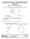
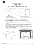
Figure 1
(1) Interface Bracket
(4) Mounting Buttons – Tapped
(4) M6 x 50mm Phillips Pan Head Screws
(1) 3mm Hex Key
(6) .750 x .250 x .250 Nylon Spacers
(4) 10-24 x .500 Phillips Pan Head Screws
(2) .750 x .194 x .500 Nylon Spacers
(4) M4 x 60mm Socket Head Cap Screws
BEFORE PROCEEDING, READ INSTALLATION INSTRUCTIONS COMPLETELY
CAUTION!
DISPLAYS ARE EXTREMELY FRAGILE.
NOTE: If installing screen on a Chief F-series swing arm mount, proceed to Step 2.
1.
Chief Q2 Button Installation (Used with M-series mounts):
Using a 10-24 button head cap screw inserted from back side of bracket, secure mounting button, with
chamfered hole of mounting button (larger surface) facing bracket (four places) (see Figure 2 & Figure3).
Figure 2
CHIEF MANUFACTURING INC.
1-800-582-6480 952-894-6280 FAX 952-894-6918
8401 EAGLE CREEK PKWY, STE. 700
SAVAGE, MINNESOTA 55378 USA
Figure 3
8835-000001 Rev01
2006 Chief Manufacturing
www.chiefmfg.com
03/06
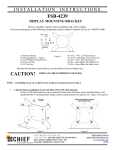
2. Bracket Installation: Place nylon spacers over mounting holes of screen and attach brackets to back of display
using the nylon spacers along with the M6 & M4 screws (see Figure 4 & Figure 5). Do
not over tighten screws.
Figure 4
3. Follow the Chief mount instruction manual for screen installation.
Figure 5