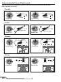
1
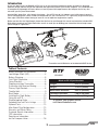
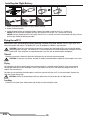
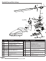
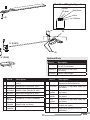
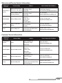
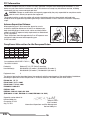
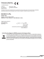
RTF Instruction Manual Bedienungsanleitung Manuel d’utilisation Manuale di Istruzioni NOTICE All instructions, warranties and other collateral documents are subject to change at the sole discretion of Horizon Hobby, Inc. For up-to-date product literature, visit horizonhobby.com and click on the support tab for this product. Meaning of Special Language The following terms are used throughout the product literature to indicate various levels of potential harm when operating this product: NOTICE: Procedures, which if not properly followed, create a possibility of physical property damage AND a little or no possibility of injury. CAUTION: Procedures, which if not properly followed, create the probability of physical property damage AND a possibility of serious injury. WARNING: Procedures, which if not properly followed, create the probability of property damage, collateral damage, and serious injury OR create a high probability of superficial injury. WARNING: Read the ENTIRE instruction manual to become familiar with the features of the product before operating. Failure to operate the product correctly can result in damage to the product, personal property and cause serious injury. This is a sophisticated hobby product. It must be operated with caution and common sense and requires some basic mechanical ability. Failure to operate this Product in a safe and responsible manner could result in injury or damage to the product or other property. This product is not intended for use by children without direct adult supervision. Do not attempt disassembly, use with incompatible components or augment product in any way without the approval of Horizon Hobby, Inc. This manual contains instructions for safety, operation and maintenance. It is essential to read and follow all the instructions and warnings in the manual, prior to assembly, setup or use, in order to operate correctly and avoid damage or serious injury. Additional Safety Precautions and Warnings Age Recommendation: Not for children under 14 years. This is not a toy. • Always keep aircraft in sight and under control. • Always keep a safe distance in all directions around your model to avoid collisions or injury. This model is controlled by a radio signal subject to interference from many sources outside your control. Interference can cause momentary loss of control. • Always use fully charged batteries. • Always operate your model in open spaces away from full-size vehicles, traffic and people. • Always keep moving parts clean. • Always carefully follow the directions and warnings for this and any optional support equipment (chargers, rechargeable battery packs, etc.). • Always keep all chemicals, small parts and anything electrical out of the reach of children. • Always move the throttle fully down at rotor strike. • Always keep transmitter powered on while aircraft is powered. • Always remove batteries before disassembly • Always keep parts dry. • Always let parts cool after use before touching. • Always remove batteries after use. • Never operate aircraft with damaged wiring. • Never touch moving parts. • Always avoid water exposure to all equipment not specifically designed and protected for this purpose. Moisture causes damage to electronics. • Never place any portion of the model in your mouth as it could cause serious injury or even death. • Never operate your model with low transmitter batteries. EN 2 Introduction As you are about to see, the Blade® mCP X truly is an ultra micro heli experience unlike any other. Its advanced flybarless design reduces drag on the rotorhead and significantly boosts cyclic control response. This, combined with its exceptionally lightweight airframe, delivers a level of power and responsiveness that eclipses that of any ultra micro heli you may have flown before. Inverted flight, loops, flips, rolls, funnels, hurricanes – the mCP X can do it all, indoors or out, with power to spare. If you’re transitioning from a basic CCPM or fixed-pitched heli, you’ll find the mCP X is a great way to get used to flying more agile CCPM helis without having to invest in a lot of expensive equipment or repairs. Before you take the first flight though, please take the time to read through this manual and watch the included DVD. Both contain important pre-flight information as well as useful tips on binding your transmitter that will help ensure your first flight is a great one. *Transmitter and AA Batteries not included with BNF Version Table of Contents RTF Battery Warnings and Guidelines.................4 Low Voltage Cutoff (LVC).............................4 Battery Charging........................................5 First Flight Preparation...............................5 Flying Checklist..........................................5 Programming Your Transmitter....................6 Transmitter and Receiver Binding................7 Primary Flight Controls...............................8 Throttle Hold..............................................9 Stunt Mode................................................9 Installing the Flight Battery.......................10 Flying the mCP X.....................................10 Troubleshooting Guide..............................11 Exploded View and Parts Listings..............12 Optional Parts..........................................13 Main Board Plug Configuration..................13 Warranty and Repair Policy.......................14 Customer Service Information...................15 FCC Information.......................................16 Compliance Information for the European Union.............................16 BLH3600 BLH3680 Blade mCP X Specifications Length 9.25 in (235mm) Height 3.65 in (93mm) Main Rotor Diameter 9.65 in (245mm) Tail Rotor Diameter 1.40 in (36.5mm) Gross Weight 1.60 oz (45.5 g) To register your product online, visit www.bladehelis.com 3 EN Battery Warnings and Guidelines The Battery Charger (EFLC1006) included with the Blade mCP X has been designed to safely charge the Li-Po battery. CAUTION: All instructions and warnings must be followed exactly. Mishandling of Li-Po batteries can result in a fire, personal injury, and/or property damage. • By handling, charging or using the included Li-Po battery, you assume all risks associated with lithium batteries. • If at any time the battery begins to balloon or swell, discontinue use immediately. If charging or discharging, discontinue and disconnect. Continuing to use, charge or discharge a battery that is ballooning or swelling can result in fire. • Always store the battery at room temperature in a dry area for best results. • Always transport or temporarily store the battery in a temperature range of 40–120º F. Do not store battery or model in a car or direct sunlight. If stored in a hot car, the battery can be damaged or even catch fire. • NEVER USE A Ni-Cd OR Ni-MH CHARGER. Failure to charge the battery with a compatible charger may cause fire resulting in personal injury and/or property damage. • Never exceed the recommended charge rate. • Never discharge Li-Po cells to below 3V under load. • Never cover warning labels with hook and loop strips. WARNING: Only use an E-flite 6V power supply with this charger. DO NOT use a 12V power supply or property damage and injury could occur. Low Voltage Cutoff (LVC) When a Li-Po battery is discharged below 3V, the battery may be damaged and may no longer accept a charge. The mCP X 3-in-1 control unit protects the flight battery from over-discharge by using Low Voltage Cutoff (LVC). Before the battery charge decreases too much, LVC removes power supplied to the motor. As power to the motor decreases, the LED on the 3-in-1 control unit blinks, showing some battery power is reserved for flight control and safe landing. When the motor power decreases, land the aircraft immediately and recharge the flight battery. Disconnect and remove the Li-Po battery from the aircraft after each use to prevent trickle discharge. Before storage, charge the Li-Po battery to full capacity. During storage, make sure the battery charge does not fall below 3V. NOTICE: Repeated flying to LVC will damage the battery. EN 4 Battery Charging Celectra™ 1-Cell 3.7V Variable Rate DC Li-Po Charger Instructions 1. C onnect the power supply to an appropriate power source. 2. Insert the output plug from the power supply into the power input slot of the Variable Rate Charger. 3. Select the appropriate charge current for your battery by pushing the + or -, which are the smaller buttons to the right and left of the Start (middle) button, (When charging your 200mAh battery, set the charger to 0.7 amps). 4. Connect the charge adapter to the Charger lead. Match the red dots on both the charge adapter and the Charger lead. 5. P roperly connect the battery to the Charger lead. Match the red dots on both the battery and charger connectors. 6. Press the start button on the Variable rate charger to begin the charging process. Notice: Only use the included charger. CAUTION: NEVER attempt to power the charger from an AC outlet without the use of a proper AC to DC adapter/power supply. CAUTION: DO NOT connect charged or discharged Li-Po batteries if the power supply is connected to the charger while the power supply is not connected to a power source. Doing so will discharge and possibly damage the batteries. LED functions under normal operation: SINGLE SOLID LED SINGLE LED FLASHING MULTIPLE LEDs FLASHING LEDs SWEEPING SIDE TO SIDE First Flight Preparation Shows Charge Current Charging Charge Almost Complete Charge Complete Flying Checklist • Remove and inspect contents • Begin charging the flight battery • Install the four AA batteries in the transmitter (RTF ONLY) • Install the blades appropriate to your flying style. The Fast Flight Main Rotor Blade Set is best used for outdoors or a smoother flying style. The High-performance Main Rotor Blade Set is intended for indoors or aggressive aerobatic maneuvers • Install the flight battery in the helicopter (once it has been fully charged) • Program your computer transmitter (BNF Only) • Test the controls • Familiarize yourself with the controls • Find a suitable area for flying 5 ❏❏ Always turn the transmitter on first ❏❏ Plug the flight battery into the lead from the 3-in-1 control unit ❏❏ Allow the 3-in-1 control unit to initialize and arm properly ❏❏ Fly the model ❏❏ Land the model ❏❏ Unplug the flight battery from the 3-in-1 control unit ❏❏ Always turn the transmitter off last EN ® Programming Your Transmitter (Computer Transmitters Only) Program your transmitter before attempting to bind or fly the helicopter. If the throttle and pitch programming values are incorrect, the helicopter will not respond. Transmitter programming values are shown below for the Spektrum DX6i, DX7 and DX8. The Spektrum DX8 model file is also available for download online at the Spektrum DX8 Community. DX6i SETUPLIST LIST SETUP SETUP LIST ModelType Type Model Model HELI Type HELI HELI Reverse Reverse Reverse THRO-N THRO-N THRO-N AILE-N AILE-N AILE-N ELEV-N ELEV-N ELEV-N RUDD-N RUDD-N RUDD-N GYRO-N GYRO-N GYRO-N PITC-R PITC-R PITC-R SwashType Type Swash Swash ServoType 90 11Servo 90 1 Servo 90 Timer Timer Timer 4:00 Basic BasicFlying Flying 4:00 4:00 FlyingFlying 3:00 Basic Advanced 3:00 Advanced Flying 3:00 Advanced Flying ADJUSTLIST LIST ADJUST ADJUST LIST D/R&&Expo Expo D/R D/R & Expo 0-AILE 70% 0-AILE 70% 0-AILE 70% 0-ELEV 70% 0-ELEV 70% 0-ELEV 70% 0-RUDD 100% 0-RUDD 100% 0-RUDD 100% 1-AILE 100% 1-AILE 100% 1-AILE 100% 1-ELEV 100% 1-ELEV 100% 1-ELEV 100% 1-RUDD 100% 1-RUDD 100% 1-RUDD 100% TravelAdj Adj Travel Travel THRO Adj 100% THRO 100% THRO 100% AILE 100% AILE 100% AILE 100% ELEV 100% ELEV 100% ELEV 100% RUDD 100% RUDD 100% RUDD 100% GYRO 100% GYRO 100% GYRO 100% PITC 75% PITC 75% PITC 75% 30% 30% 30% 30% 30% 30% INH INH INH 30% 30% 30% 30% 30% 30% INH INH INH ThroCurve Curve Thro Thro Curve NORM NORM NORM STUNT STUNT STUNT HOLD HOLD HOLD 0% 0% 0% 100% 100% 100% 0% 0% 0% 40% 40% 40% 100% 100% 100% 0% 0% 0% 60% 60% 60% 100% 100% 100% 0% 0% 0% 80% 80% 80% 100% 100% 100% 0% 0% 0% 100% 100% 100% 100% 100% 100% 0% 0% 0% PitcCurve Curve Pitc Pitc Curve NORM NORM NORM STUNT STUNT STUNT HOLD HOLD HOLD 30% 30% 30% 0% 0% 0% 0% 0% 0% 40% 40% 40% 25% 25% 25% 25% 25% 25% 50% 50% 50% 50% 50% 50% 50% 50% 50% 75% 75% 75% 75% 75% 75% 75% 75% 75% 100% 100% 100% 100% 100% 100% 100% 100% 100% DX7/DX7se SYSTEMLIST LIST SYSTEM SYSTEM LIST ModelType Type Model Model HELI Type HELI HELI SwashType Type Swash Swash ServoType 90 11Servo 90 1 Servo 90 DX8 SYSTEM SETUP SYSTEM SETUP SYSTEM SETUP Model Type Model Type Model HELI Type HELI HELI Swash Type Swash Type Swash 1 ServoType Normal 1 Servo Normal 1 Servo Normal F-Mode Setup F-Mode Setup Flight Mode: F-Mode SetupF Mode Flight Mode: F Mode Hold:Mode: Hold F Mode Flight Hold: Hold Hold: Hold EN FUNCTION MODE MODE FUNCTION FUNCTION MODE D/R&&EXP EXP D/R D/R & EXP EXP EXP EXP 0-AILE 30% 0-AILE 30% 0-AILE 30% 0-ELEV 30% 0-ELEV 30% 0-ELEV 30% 0-RUDD INH 0-RUDD INH 0-RUDD INH 1-AILE 30% 1-AILE 30% 1-AILE 30% 1-ELEV 30% 1-ELEV 30% 1-ELEV 30% 1-RUDD INH 1-RUDD INH 1-RUDD INH TravelAdj Adj Travel Travel THRO Adj 100% THRO 100% THRO 100% AILE 100% AILE 100% AILE ELEV 100% 100% ELEV 100% ELEV RUDD 100% 100% RUDD 100% RUDD GEAR 100% 100% GEAR 100% GEAR PIT. 100% 75% PIT. 75% PIT. 75% D/R D/R D/R 70% 70% 70% 70% 70% 70% 100% 100% 100% 100% 100% 100% 100% 100% 100% 100% 100% 100% FUNCTIONLIST LIST FUNCTION FUNCTION LIST D/R & Expo D/R & Expo D/R & Expo 0-AILE 70% 30% 0-AILE 70% 30% 0-AILE 70% 0-ELEV 70% 30% 30% 0-ELEV 70% 30% 0-ELEV 70% 0-RUDD 100% 30% 0% 0-RUDD 100% 0% 0-RUDD 100% 1-AILE 100% 0% 30% 1-AILE 100% 30% 1-AILE 100% 1-ELEV 100% 30% 30% 1-ELEV 100% 30% 1-ELEV 100% 1-RUDD 100% 30% 0% 1-RUDD 100% 0% 1-RUDD 100% 2-AILE 100% 0% 30% 2-AILE 100% 30% 2-ELEV 100% 30% 30% 2-AILE 100% 2-ELEV 100% 30% 2-RUDD 100% 30% 0% 2-ELEV 100% 2-RUDD 100% 0% 2-RUDD SERVO SETUP 100% 0% SERVO SETUP Travel SETUP Reverse SERVO Reverse Travel THRO 100% THRO - N Travel Reverse THRO 100% THRO - N AILE 100% 100% AILE - N THRO THRO AILE 100% AILE - N ELEV 100% 100% ELEV- N- N AILE AILE ELEV - N ELEV 100% RUDD 100% 100% RUDD ELEV ELEV - N- N RUDD - N RUDD 100% GEAR 100% GEAR--NN RUDD 100% RUDD GEAR - N GEAR 100% PIT. 100% 75% PIT. --NN GEAR GEAR PIT. - N PIT. 75% PIT. 75% PIT. - N ThroCurve Curve Thro Thro Curve NORM 0% 40% 40% 60% 60% 80% 80% 100% 100% NORM 0% NORM 0% ST-1 100% 40% INH 60% 80% 80% INH% 100% 100% ST-1 100% INH 80% INH% 100% ST-1 100% INH 80% INH% 100% ST-2 100% 100% 100% 100% 100% ST-2 100% 100% 100% 100% 100% ST-2 100% HOLD 0% 100% 0% 100% 0% 100% 0% 100% 0% HOLD 0% 0% 0% 0% 0% HOLD 0% 0% 0% 0% 0% PitcCurve Curve Pitc Pitc Curve NORM 30% INH 50% INH 100% NORM 30% INH 50% INH 100% NORM 30% STUNT 0% INH INH 50% 50% INH INH 100% 100% STUNT 0% INH 50% INH 100% STUNT 0% INH 50% INH 100% HOLD 0% INH INH 50% 50% INH INH 100% 100% HOLD 0% HOLD 0% INH 50% INH 100% ReversingSW SW Timer Reversing Timer Reversing Timer THRO-N SW RUDD-N RUDD-N 4:00 Basic BasicFlying Flying THRO-N 4:00 THRO-N RUDD-N 4:00 FlyingFlying AILE-N GEAR-N 3:00 Basic Advanced AILE-N GEAR-N 3:00 Advanced Flying AILE-N GEAR-N 3:00 Advanced Flying ELEV-N PIT.-N ELEV-N PIT.-N ELEV-N PIT.-N Throttle Curve Throttle Curve Throttle NORM Curve 0% 40% 60% NORM 0% 40% 60% NORM 0% ST-1 100% 40% 90% 60% 80% ST-1 100% 90% 80% ST-1 100% 90% ST-2 100% 100% 80% 100% ST-2 100% 100% 100% ST-2 100% HOLD 0% 100% 0% 100% 0% HOLD 0% 0% 0% HOLD 0% 0% 0% Pitch Curve Pitch Curve Pitch NOR Curve 30% 40% 50% NOR 30% 40% 50% ST-1 0% 40% 25% 50% 50% NOR 30% ST-1 0% 25% 50% ST-2 0% 25% 25% 50% 50% ST-1 0% ST-2 0% 25% 50% HOLD 0% 25% 25% 50% 50% ST-2 0% HOLD 0% 25% 50% HOLD 0% 25% 50% Timer Timer 4:00 Basic Flying Timer 4:00 Basic Flying 3:00 Basic Advanced 4:00 FlyingFlying 3:00 Advanced Flying 3:00 Advanced Flying 6 80% 80% 80% 90% 90% 90% 100% 100% 100% 0% 0% 0% 100% 100% 100% 100% 100% 100% 100% 100% 100% 0% 0% 0% 75% 75% 75% 75% 75% 75% 75% 75% 75% 75% 75% 75% 100% 100% 100% 100% 100% 100% 100% 100% 100% 100% 100% 100% ® Transmitter and Receiver Binding If you purchased an RTF model, the transmitter is bound to the model at the factory. To bind or re-bind your mCP X to your chosen transmitter, please follow the directions below: Binding is the process of programming the receiver of the control unit to recognize the GUID (Globally Unique Identifier) code of a single specific transmitter. You need to ‘bind’ your chosen Spektrum™ or JR® DSM® technology equipped aircraft transmitter to the receiver for proper operation. NOTICE: Use the Non-Computer Radio binding instructions if you are using a DX4e or DX5e transmitter with the mCP X BNF. Binding Procedure for Computer Radios: 1. Disconnect the flight battery from the helicopter. 2. Power off the transmitter and move all switches to the 0 position. 3. Connect the flight battery to the helicopter. The 3-in-1 Control unit LED flashes after 5 seconds. 4. Push in on the bind switch/button while powering on the transmitter. 5. After 2–3 seconds, release the bind switch/button. 6. Move the rudder control stick to full right. Continue to hold the rudder control stick to full right until the blue LED on the 3-in-1 control unit is solid. 7. Release the rudder control stick. 8. Disconnect the flight battery and power the transmitter off. The throttle will not arm if the transmitter’s throttle control is not put at the lowest position and the stunt mode switch is not in the 0 position. If you encounter problems, obey binding instructions and refer to the troubleshooting guide for other instructions. If needed, contact the appropriate Horizon Product Support office. For a list of compatible DSM transmitters, please visit www.bindnfly.com. Binding Procedure for Non-Computer Radio (DX4e, DX5e) 1. Disconnect the flight battery from the helicopter. 2. Power off the transmitter and move all switches to the 0 position. 3. Connect the flight battery to the helicopter. The 3-in-1 Control unit LED flashes after 5 seconds. 4. Push in on the trainer switch or button while powering on the transmitter. 5. Move the rudder control stick to full left after the transmitter LED lights flash twice. 6. Release the trainer switch/button. Continue to hold the rudder control stick to full left until the blue LED on the 3-in-1 control unit is solid. 7. Release the rudder control stick. 8. Push in on the trainer switch/button. The blue LED on the 3-in-1 control unit flashes to confirm the helicopter is in non-computer mode. 9. Disconnect the flight battery and power the transmitter off. If the swashplate moves up and down when the trainer switch is moved, the helicopter is in computer transmitter mode; repeat binding procedure. 7 EN Understanding the Primary Flight Controls If you are not familiar with the controls of your mCP X, take a few minutes to familiarize yourself with them before attempting your first flight. Throttle Descend Ascend Throttle up Throttle down Rudder Nose Yaws Left Rudder left Nose Yaws Right Rudder right Elevator Backward Forward Elevator up Elevator down Aileron Left Aileron left EN Right Aileron right 8 Throttle Hold Throttle hold is used to turn off the helicopter motors if the helicopter is out of control, in danger of crashing or both. Activate throttle hold anytime the helicopter is in danger to reduce the chance of damaging the helicopter in a crash. Throttle hold will stop the motor in normal or stunt mode. Throttle Hold ON (DX4e) Press the trainer button anytime to turn throttle hold ON after connecting the battery to the helicopter. The blue LED flashes, indicating throttle hold is ON. Throttle Hold OFF (DX4e) 1. Make sure the AUX switch is in the OFF position. 2. Lower the throttle stick. 3. Press the trainer button three times within 3 seconds. The blue LED is solid. 1. 1. 2. 2. 3. 3. X3 Throttle Hold ON (DX5e) Pull the trainer switch anytime to turn throttle hold ON after connecting the battery to the helicopter. The blue LED flashes, indicating throttle hold is ON. Throttle Hold OFF (DX5e) 1. Make sure the Gear switch is in the (0) position. 2. Lower the throttle stick. 3. Pull the trainer switch three times within 3 seconds. The blue LED is solid. 1. 1. 2. 2. 3. 3. X3 Stunt Mode Stunt Mode allows the helicopter to fly inverted and perform aerobatics. The throttle runs continuously when Stunt Mode is ON, regardless of throttle stick position. Turn Stunt Mode OFF to return control to the throttle stick. Use the AUX/ACT switch on the DX4e transmitter or Gear switch on the DX5e transmitter to activate Stunt Mode. DX4e – AUX/ACT OFF – Normal Mode DX5e – Ch 5 (0) – Normal Mode DX5e – Ch 5 (1) – Stunt Mode AUX/ACT ON – Stunt Mode 9 EN Installing the Flight Battery 1. Lower the throttle and throttle trim to the lowest settings. 2. Power on the transmitter. 3. Install the flight battery in the battery holder. Connect the battery cable to the 3-in-1 control unit. NOTICE: Do not allow the helicopter to move until the blue LED on the 3-in-1 control unit is solid. NOTICE: Always disconnect the Li-Po battery from the 3-in-1 control unit of the aircraft when not flying. Failure to do so will render the battery unusable. Flying the mCP X Consult local laws and ordinances before choosing a location to fly your aircraft. Select a large, open area away from people and objects. The Blade mCP X can fly outdoors or indoors in a gymnasium. CAUTION: Please take a few minutes to familiarize yourself with the Blade mCP X primary controls before attempting your first flight. The Blade mCP X is more responsive than other Blade micro helicopters like the Blade mSR. Seek help from an experienced pilot if you are new to collective pitch helicopters. Takeoff Gradually increase the throttle to allow the helicopter time to increase rotor head speed. CAUTION: Do not give any aileron, elevator or rudder commands before takeoff or the helicopter may crash. Flying The helicopter lifts off the ground when the rotor head reaches a suitable speed. Establish a low-level hover to verify proper operation of your helicopter. You will not need to set any trim; the flybarless design of the mCP X renders trim unnecessary. For pilots new to collective pitch helicopters, familiarize yourself with your mCP X in normal mode. Discover the rates that fit your flying style. CAUTION: Always fly the helicopter with your back to the sun to prevent loss of flight control. Landing Establish a low level hover. Slowly lower the throttle until the helicopter lands. EN 10 Troubleshooting Guide Problem Possible Cause Solution Throttle at high position Reset controls with throttle stick and throttle trim at center or lowest setting Switches not in normal position Set flight mode to OFF/0 and exit throttle hold. Pitch or throttle servo reversing improperly configured Reset servo reversing Refer to “Programming your Transmitter” Throttle hold on Turn off HOLD with throttle low and trim centered or low. Refer to “Throttle Hold” Low battery voltage Completely recharge flight battery Receiver uses default soft Low Voltage Cutoff (LVC) Recharge flight battery or replace battery that is no longer performing Stunt Mode switch still on Set flight mode to OFF/ 0 and exit throttle hold. Throttle not at low position Reset controls with throttle stick and throttle trim at center or lowest setting Powers off when flying upside down (inverted) Stunt Mode off When flying, switch stunt mode to ON/1 before flying inverted. Will not bind properly to non-computer radio Helicopter binds differently to non-computer radios Release bind button/ switch after applying left rudder. Do not hold the bind button/ switch after applying left rudder. Helicopter will not initialize Helicopter will not spool up Motor power decreases during flight Cannot turn off throttle hold Tail boom is cracked Replace tail boom Poor tail authority The tail rotor blade is warped or bent. Twist rotor blade back into position or replace. Climb out rate is greatly reduced Main gear has slipped on the main shaft. Push main gear back into position. Less than a 5-second wait after powering transmitter and before connecting flight battery to aircraft Disconnect then reconnect flight battery to aircraft Transmitter too near aircraft during binding process Move powered transmitter a few feet from aircraft, disconnect and reconnect flight battery to aircraft Aircraft not bound to transmitter Bind transmitter to aircraft receiver Aircraft bound to different model memory (ModelMatch™ radios only) Select correct model memory on transmitter Low charge in transmitter batteries Replace or charge transmitter batteries Damaged rotor blades, spindle or blade grips Check main rotor blades and blade grips for cracks or chips. Replace damaged parts. Replace bent spindle. LED on receiver flashes rapidly and aircraft will not link to transmitter Helicopter vibrates or shakes in flight 11 EN Exploded View and Parts Listings L K M J G C I H (PITC) E A N F R P D A Part # Description BLH3601 Flybarless 3-in-1 Control Unit, Receiver/ESCs/Gyros: mCPX/2 Part # Description I BLH3509 Complete Precision Swashplate: mCP X J BLH3510 High-performance Main Rotor Blade Set with Hardware: mCP X BLH3511 Fast Flight Main Rotor Blade Set with Hardware: mCP X (not shown) B BLH3602 Tail Boom Assembly with Tail Motor/ Rotor/Mount: mCPX/2 C BLH3503 Main Motor with Pinion: mCP X D BLH3504 Landing Skid and Battery Mount: mCP X K BLH3512 Main Rotor Hub with Hardware: mCP X E BLH3505 Main Frame with hardware: mCP X L BLH3513 F BLH3506 EFLH3006 Main Gear: BMSR, mCP X Feathering Spindle with O-rings, Bushings, and Hardware: mCP X M BLH3514 Main Blade Grips with Bearings: mCP X G BLH3507 Carbon Fiber Main Shaft with Collar and Hardware: mCP X N BLH3515 EFLH2215 H BLH3508 Servo Pushrod Set with Ball Links (3): mCP X Main Shaft Bearing 3x6x2mm(2):BMCX/2/MSR, FHX, MH35, mCP X O BLH3603 Tail Rotor (1): mCPX/2 EN 12 Main Board Plug Configuration Elevator Aileron Main Motor Pitch S Tail Motor O B U (ELEV) Q V (AILE) Optional Parts T Part # Description P BLH3518 Complete Red Canopy with Vertical Fin: mCP X Q BLH3520R Red Vertical Fin with Decal: mCP X R BLH3521 EFLH3021 Canopy Mounting Grommets (8): BMCX2/T, MSR, FHX, MH-35, mCP X S BLH3522 Rotor Head Linkage Set (8): mCP X BLH3523 Hardware Set: mCP X (not shown) EFLB 2001S30 200mAh 1S 3.7V 30C Li-Po Battery EFLA 7002UM 1s High Current Ultra Micro Battery Adapter Lead (not shown) SPMAS 2000LBB 1.8-Gram Linear Ultra Micro Servo T U 13 V Part # Description BLH3519 Complete Green Canopy with Vertical Fin: mCP X (not shown) BLH3520G Green Vertical Fin with Decal (not shown) EFLC1004 Celectra 4 port charger Part # Description SPM6833 1.8-Gram Linear Ultra Micro Servo Replacement Servo Mechanics EFLC1005 AC to 6VDC 1.5-Amp Power Supply (US) (not shown) EFLC 1005UK AC to 6VDC 1.5-Amp Power Supply (UK) (not shown) EFLC 1005EU AC to 6VDC 1.5-Amp Power Supply (EU) (not shown) EFLC 1005AU AC to 6VDC 1.5-Amp Power Supply (AU) (not shown) EFLC1006 Celectra 1S 3.7 Variable Rate DC Li-Po Charger (not shown) EFLH2226 Body/Canopy Mounting O-Ring (8): BMCX/MSR EN Limited Warranty What this Warranty Covers Horizon Hobby, Inc., (Horizon) warranties that the Products purchased (the “Product”) will be free from defects in materials and workmanship at the date of purchase by the Purchaser. What is Not Covered This warranty is not transferable and does not cover (i) cosmetic damage, (ii) damage due to acts of God, accident, misuse, abuse, negligence, commercial use, or due to improper use, installation, operation or maintenance, (iii) modification of or to any part of the Product, (iv) attempted service by anyone other than a Horizon Hobby authorized service center, or (v) Products not purchased from an authorized Horizon dealer. OTHER THAN THE EXPRESS WARRANTY ABOVE, HORIZON MAKES NO OTHER WARRANTY OR REPRESENTATION, AND HEREBY DISCLAIMS ANY AND ALL IMPLIED WARRANTIES, INCLUDING, WITHOUT LIMITATION, THE IMPLIED WARRANTIES OF NON-INFRINGEMENT, MERCHANTABILITY AND FITNESS FOR A PARTICULAR PURPOSE. THE PURCHASER ACKNOWLEDGES THAT THEY ALONE HAVE DETERMINED THAT THE PRODUCT WILL SUITABLY MEET THE REQUIREMENTS OF THE PURCHASER’S INTENDED USE. Purchaser’s Remedy Horizon’s sole obligation and purchaser’s sole and exclusive remedy shall be that Horizon will, at its option, either (i) service, or (ii) replace, any Product determined by Horizon to be defective. Horizon reserves the right to inspect any and all Product(s) involved in a warranty claim. Service or replacement decisions are at the sole discretion of Horizon. Proof of purchase is required for all warranty claims. SERVICE OR REPLACEMENT AS PROVIDED UNDER THIS WARRANTY IS THE PURCHASER’S SOLE AND EXCLUSIVE REMEDY. Limitation of Liability HORIZON SHALL NOT BE LIABLE FOR SPECIAL, INDIRECT, INCIDENTAL OR CONSEQUENTIAL DAMAGES, LOSS OF PROFITS OR PRODUCTION OR COMMERCIAL LOSS IN ANY WAY, REGARDLESS OF WHETHER SUCH CLAIM IS BASED IN CONTRACT, WARRANTY, TORT, NEGLIGENCE, STRICT LIABILITY OR ANY OTHER THEORY OF LIABILITY, EVEN IF HORIZON HAS BEEN ADVISED OF THE POSSIBILITY OF SUCH DAMAGES. Further, in no event shall the liability of Horizon exceed the individual price of the Product on which liability is asserted. As Horizon has no control over use, setup, final assembly, modification or misuse, no liability shall be assumed nor accepted for any resulting damage or injury. By the act of use, setup or assembly, the user accepts all resulting liability. If you as the purchaser or user are not prepared to accept the liability associated with the use of the Product, purchaser is advised to return the Product immediately in new and unused condition to the place of purchase. Law These terms are governed by Illinois law (without regard to conflict of law principals). This warranty gives you specific legal rights, and you may also have other rights which vary from state to state. Horizon reserves the right to change or modify this warranty at any time without notice. EN WARRANTY SERVICES Questions, Assistance, and Services Your local hobby store and/or place of purchase cannot provide warranty support or service. Once assembly, setup or use of the Product has been started, you must contact your local distributor or Horizon directly. This will enable Horizon to better answer your questions and service you in the event that you may need any assistance. For questions or assistance, please direct your email to productsupport@ horizonhobby.com, or call 877.504.0233 toll free to speak to a Product Support representative. You may also find information on our website at www.horizonhobby.com. Inspection or Services If this Product needs to be inspected or serviced, please use the Horizon Online Service Request submission process found on our website or call Horizon to obtain a Return Merchandise Authorization (RMA) number. Pack the Product securely using a shipping carton. Please note that original boxes may be included, but are not designed to withstand the rigors of shipping without additional protection. Ship via a carrier that provides tracking and insurance for lost or damaged parcels, as Horizon is not responsible for merchandise until it arrives and is accepted at our facility. An Online Service Request is available at http://www.horizonhobby.com under the Support tab. If you do not have internet access, please contact Horizon Product Support to obtain a RMA number along with instructions for submitting your product for service. When calling Horizon, you will be asked to provide your complete name, street address, email address and phone number where you can be reached during business hours. When sending product into Horizon, please include your RMA number, a list of the included items, and a brief summary of the problem. A copy of your original sales receipt must be included for warranty consideration. Be sure your name, address, and RMA number are clearly written on the outside of the shipping carton. Notice: Do not ship LiPo batteries to Horizon. If you have any issue with a LiPo battery, please contact the appropriate Horizon Product Support office. Warranty Requirements For Warranty consideration, you must include your original sales receipt verifying the proof-of-purchase date. Provided warranty conditions have been met, your Product will be serviced or replaced free of charge. Service or replacement decisions are at the sole discretion of Horizon. Non-Warranty Service Should your service not be covered by warranty service will be completed and payment will be required without notification or estimate of the expense unless the expense exceeds 50% of the retail purchase cost. By submitting the item for service you are agreeing to payment of the service without notification. Service estimates are available upon request. You must include this request with your item submitted for service. Non-warranty service estimates will be billed a minimum of ½ hour of labor. In addition you will be billed for return freight. Horizon accepts money orders and cashiers checks, as well as Visa, MasterCard, American Express, and Discover cards. By submitting any item to Horizon for service, you are agreeing to Horizon’s Terms and Conditions found on our website http:// www.horizonhobby.com/Service/Request/. 14 Warranty and Service Contact Information Country of Purchase Horizon Hobby Address 4105 Fieldstone Rd Horizon Service Center Champaign, Illinois (Electronics and engines) 61822 USA United States of America 4105 Fieldstone Rd Horizon Product Support Champaign, Illinois (All other products) 61822 USA Units 1-4 Ployters Rd Staple Tye United Kingdom Horizon Hobby Limited Harlow, Essex CM18 7NS United Kingdom Hamburger Str. 10 Horizon Technischer Germany 25335 Elmshorn Service Germany 14 Rue Gustave Eiffel France Horizon Hobby SAS Zone d’Activité du Réveil Matin 91230 Montgeron Phone Number/Email Address 877-504-0233 Online Repair Request: visit www.horizonhobby.com/service 877-504-0233 [email protected] +44 (0) 1279 641 097 [email protected] +49 4121 46199 66 [email protected] +33 (0) 1 60 47 44 70 [email protected] Customer Service Information Country of Purchase United States of America Horizon Hobby Address 4105 Fieldstone Rd Sales Champaign, Illinois 61822 USA Phone Number/Email Address (800) 338-4639 [email protected] Units 1-4 Ployters Rd Staple Tye United Kingdom Horizon Hobby Limited Harlow, Essex CM18 7NS +44 (0) 1279 641 097 [email protected] United Kingdom Hamburger Str. 10 Germany Horizon Hobby GmbH 25335 Elmshorn Germany 14 Rue Gustave Eiffel France Horizon Hobby SAS Zone d’Activité du Réveil Matin 91230 Montgeron 15 +49 4121 46199 60 [email protected] +33 (0) 1 60 47 44 70 [email protected] EN FCC Information This device complies with part 15 of the FCC rules. Operation is subject to the following two conditions: (1) This device may not cause harmful interference, and (2) this device must accept any interference received, including interference that may cause undesired operation. Caution: Changes or modifications not expressly approved by the party responsible for compliance could void the user’s authority to operate the equipment. This product contains a radio transmitter with wireless technology which has been tested and found to be compliant with the applicable regulations governing a radio transmitter in the 2.400GHz to 2.4835GHz frequency range. Antenna Separation Distance When operating your E-flite transmitter, please be sure to maintain a separation distance of at least 5 cm between your body (excluding fingers, hands, wrists, ankles and feet) and the antenna to meet RF exposure safety requirements as determined by FCC regulations. These illustrations show the approximate 5 cm RF exposure area and typical hand placement when operating your E-flite transmitter. Compliance Information for the European Union AT BG CZ CY DE DK ES FI FR GR LU HU IE IT LT LV MT NL PL PT RO SE SI SK UK Declaration of Conformity (in accordance with ISO/IEC 17050-1) No. HH2011081401 Product(s): Blade mCP X 2 RTF (DX4e Transmitter) Item Number(s): BLH3600EU1 (EU mode 1), BLH3600EU2 (EU mode 2), BLH3600UK1 (UK mode 1), BLH3600UK2 (UK mode 2) Equipment class: 2 The object of declaration described above is in conformity with the requirements of the specifications listed below, following the provisions of the European R&TTE Directive 1999/5/EC and EMC Directive 2004/108/EC: EN 300-328 V1.7.1 EN 301 489-1 V1.7.1: 2006 EN 301 489-17 V1.3.2: 2008 EN 60950-1:2006+A11 EN55022: 2006, EN55024: 1998+A1: 2001+A2: 2003 (EN61000-4-2: 2001, EN61000-4-3: 2006, EN61000-4-8: 2001) Signed for and on behalf of: Horizon Hobby, Inc. Champaign, IL USA Aug 14, 2011 EN Steven A. Hall Vice President International Operations and Risk Management Horizon Hobby, Inc. 16 Declaration of Conformity (in accordance with ISO/IEC 17050-1) No. HH2011081402 Product(s): Blade mCP X 2 BNF Item Number(s): Equipment class: BLH3680EU, BLH3680UK 1 The object of declaration described above is in conformity with the requirements of the specifications listed below, following the provisions of the European R&TTE Directive 1999/5/EC and EMC Directive 2004/108/EC: EN 301 489-1 V1.7.1: 2006 EN 301 489-17 V1.3.2: 2008 EN55022: 2006, EN55024: 1998+A1: 2001+A2: 2003 (EN61000-4-2: 2001, EN61000-4-3: 2006, EN61000-4-8: 2001) Signed for and on behalf of: Horizon Hobby, Inc. Champaign, IL USA Aug 14, 2011 Steven A. Hall Vice President International Operations and Risk Management Horizon Hobby, Inc. Instructions for disposal of WEEE by users in the European Union This product must not be disposed of with other waste. Instead, it is the user’s responsibility to dispose of their waste equipment by handing it over to a designated collections point for the recycling of waste electrical and electronic equipment. The separate collection and recycling of your waste equipment at the time of disposal will help to conserve natural resources and make sure that it is recycled in a manner that protects human health and the environment. For more information about where you can drop off your waste equipment for recycling, please contact your local city office, your household waste disposal service or where you purchased the product. 17 EN ©2011 Horizon Hobby, Inc Blade, E-flite, Celectra, Bind-N-Fly, DSM, JR and ModelMatch are trademarks or registered trademarks of Horizon Hobby, Inc The Spektrum trademark is used with permission of Bachmann Industries, Inc. US 7,391,320, D578,146. US 7,898,130. PRC patent number ZL 200720069025.2. Other patents pending. Created 8/11 34551 BLH3600/BLH3680