1
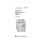
Owner’s Manual
DVI/USB + Audio &
Peripheral Sharing
KVM Switch
Model: B043-DUA8-SL
Table of Contents
Package Contents
Optional Accessories
System Requirements
Product Features
Front Panel
Safety Instructions
Rackmount Installation
System Installation
Operation
Warranty & Warranty Registration
2
2
2
2
3
4
5
5
6
8
1111 W. 35th Street, Chicago, IL 60609 USA • www.tripplite.com/support
Copyright © 2014 Tripp Lite. All rights reserved.
1
14-03-102-933345.indd 1
4/2/2014 10:43:32 AM
Package Contents
• B043-DUA8-SL KVM Switch
• External Power Supply (Input: 100-240V, 50/60Hz; Output: 9V, 2A)
• Rackmount Hardware
• Owner’s Manual
Optional Accessories
• P312-Series 3.5 mm Mini Stereo Audio Cables
• P556-Series DVI Male to VGA Male Adapter Cables
• P561-006-SLI DVI-I Single-Link Digital/Analog Cable – 6 ft.
• P561-Series DVI-D Single-Link Cables
• P759-Series DVI-D/USB/Audio KVM Cable Kits
• U022-Series USB 2.0 A/B Device Cables
• UR022-Series Reversible USB 2.0 A/B Device Cables
System Requirements
• DVI or VGA* monitor
• USB mouse and keyboard
• Computer with a DVI or VGA* port
• Computer with a USB port
• P759-Series DVI-D/USB/Audio KVM cable kit for each connected computer
• Microphone with a 3.5 mm Male connector (if using the microphone feature)
• Speakers with a 3.5 mm Male connector (if using the speaker feature)
• Compatible with all major operating systems
*Requires a DVI to VGA adapter
Product Features
• Directly connect up to 8 computers with DVI, USB, and audio.
• Expand the number of connected computers by cascading an additional level of KVM switches.
• Supports 2.1 Channel Stereo Audio and microphone.
• (x2) USB 2.0 ports for sharing peripherals among connected computers.
• USB hub functionality can be unbinded from the KVM, allowing users to access one computer
while the USB hub focus remains on another computer.
• Switch between connected computers via pushbuttons or hotkey commands.
• DVI-I Single-Link supports digital video resolutions up to 1920 x 1200, and analog video
resolutions up to 2048 x 1536.
• Auto Scan mode lets users scan connected computers without having to manually switch
between them.
• Multi-platform support – compatible with all major operating systems.
• Plug and play setup – no software installation required.
• Supports EDID (Extended Display Identification Data) transmission to connected computers for
optimal display performance.
• Includes mounting hardware for 19” rackmount installations.
2
14-03-102-933345.indd 2
4/2/2014 10:43:32 AM
Front Panel
4
5
1
6
2
3
1 USB 2.0 Hub Ports – Two hub ports allow for USB peripheral sharing among connected
computers.
2 BANK LED – This 2-digit display represents the KVM’s place in a cascaded installation hierarchy.
The first KVM in a chain will have a BANK number of 00; standalone KVM’s will also have a
BANK number of 00. A KVM that is cascaded to the PC 1 ports will have a BANK number of 01,
a KVM cascaded to the PC 2 ports will have a BANK number of 02, and so on.
3 Port Selection Pushbuttons – Press a pushbutton to bring the focus of the KVM, Audio and
USB hub to the corresponding port. Note: The USB Hub focus can be unbinded from the KVM
via keyboard hotkey. See the Operation section for details.
4 Power Jack – The included power supply connects to the KVM switch here.
5 Console Ports – Your monitor, keyboard, mouse, microphone and speakers plug into these
ports.
6 Computer Ports – Connect each set of computer ports to a computer using a P759-Series
DVI-D/USB/Audio KVM cable kit.
3
14-03-102-933345.indd 3
4/2/2014 10:43:32 AM
Safety Instructions
• Read all of these instructions and save them for future reference.
• Follow all warnings and instructions marked on the device.
• Do not place the device on any unstable surface (cart, stand, table, etc.). If the device falls,
serious damage will result.
• Do not use the device near water.
• Do not place the device near, or over, radiators or heat registers. The device cabinet is provided
with slots and openings to allow for adequate ventilation. To ensure reliable operation, and to
protect against overheating, these openings must never be blocked or covered.
• The device should never be placed on a soft surface (bed, sofa, rug, etc.), as this will block
its ventilation openings. The device also should not be placed in a built-in enclosure, unless
adequate ventilation has been provided.
• Never spill liquid of any kind on the device.
• Unplug the device from the wall outlet before cleaning. Do not use liquid or aerosol cleaners. Use
a damp cloth for cleaning.
• The device should be operated from the power source type as indicated on the marking label. If
you are not sure of the type of power available, consult your dealer or local power company.
• Do not allow anything to rest on the power cord or cables. Route the power cord and cables so
that they cannot be stepped on or tripped over.
• If an extension cord is used with this device, make sure that the total of the ampere ratings of all
products used on this cord does not exceed the extension cord ampere rating. Make sure that
the total of all products plugged into the wall outlet does not exceed 15 amperes.
• Position system cables and power cables carefully; be sure that nothing rests on any cables.
• To help protect your system from sudden transient increases and decreases in electrical power, it
is recommended that you plug your devices into a Tripp Lite Surge Protector, Line Conditioner, or
Uninterruptible Power Supply (UPS).
• When connecting or disconnecting power to hot-pluggable power supplies, observe the following
guidelines:
o Install the power supply to the unit before connecting the power cable to the power supply.
o Unplug the power cable before removing the power supply.
o If the system has multiple sources of power, disconnect power from the system by unplugging
all power cables from the power supplies.
• Never push objects of any kind into or through the housing slots. They may touch dangerous
voltage points or short out parts resulting in a risk of fire or electrical shock.
• Do not attempt to service the device yourself. Refer all servicing to qualified service personnel.
• If the following conditions occur, unplug the device from the wall outlet and bring it to qualified
service personnel for repair.
o The power cord or plug has become damaged or frayed.
o Liquid has seeped into the device.
o The device has been exposed to rain or water.
o The device has been dropped, or the housing has been damaged.
o The device exhibits a distinct change in performance, indicating a need for service.
o The device does not operate normally when the operating instructions are followed.
• Only adjust those controls that are covered in the operating instructions. Improper adjustment of
other controls may result in damage that will require extensive work by a qualified technician to repair.
• Use of this equipment in life support applications where failure of this equipment can reasonably
be expected to cause the failure of the life support equipment or to significantly affect its safety
or effectiveness is not recommended. Do not use this equipment in the presence of a flammable
anesthetic mixture with air, oxygen or nitrous oxide.
4
14-03-102-933345.indd 4
4/2/2014 10:43:32 AM
Rackmount Installation
Attach the included rackmount brackets to the KVM switch. Using user-supplied screws, fasten the
rackmount brackets to the rack.
System Installation
Standalone Installation
Note: Before making any connections, turn off the power to the KVM switch and all devices that are
being connected.
1 Connect your monitor to the DVI-I Female console port on the back panel of the KVM switch.
Note: A VGA monitor can be connected using a DVI to VGA adapter, such as Tripp Lite’s P556Series adapter cables. Computers that support analog audio through the VGA or DVI-I ports
must be connected to the KVM switch in order for video to be displayed on a VGA monitor.
2 Connect your USB keyboard and mouse to the corresponding USB console port on the back
panel of the KVM switch.
3 Connect your speakers and/or microphone to the corresponding 3.5 mm audio console ports on
the back panel of the KVM switch.
4 Using a P759-Series DVI-D/USB/Audio KVM Cable Kit, connect a computer to any of the 8
available computer ports on the back panel of the KVM unit. Note: A VGA computer can be
connected using an individual DVI to VGA adapter (such as Tripp Lite’s P556-Series adapter
cables), USB A/B device cable, and 3.5 mm audio cables. Video from a VGA computer will only
display if a VGA monitor is connected.
5 Repeat step 4 for each additional computer you are connecting.
6 Connect up to two USB 2.0 devices to the USB hub ports on the front panel of the KVM switch.
7 Connect the included power supply to the DC power jack on the back of the KVM switch, then
plug it into a Tripp Lite Surge Protector, Power Distribution Unit (PDU), Uninterruptible Power
Supply (UPS), or wall-outlet.
8 Power on all connected devices.
Cascaded Installation
Note: Before making any connections, turn off the power to the KVM switch and all devices that are
being connected.
1 Connect your monitor to the DVI-I Female console port on the back panel of the first-level KVM
switch.
2 Connect your USB keyboard and mouse to the corresponding USB console port on the back
panel of the first-level KVM switch.
3 Connect your speakers and/or microphone to the corresponding 3.5 mm audio console ports on
the back panel of the first-level KVM switch.
4 Using a P759-Series DVI-D/USB/Audio KVM Cable Kit, connect the console ports of the secondlevel KVM switch to any of the 8 available computer ports on the back panel of the first-level
KVM unit.
5 Repeat step 4 for each additional KVM you are cascading.
Note: Only 1 additional level of KVM switches can be cascaded for a maximum of 64 ports.
6 Connect a computer to any of the first- or second-level KVM switches’ available computer ports
using a P759-Series DVI-D/USB/Audio KVM Cable Kit.
7 Repeat step 6 for each additional computer you are connecting.
5
14-03-102-933345.indd 5
4/2/2014 10:43:32 AM
System Installation
8 Connect up to two USB 2.0 devices to the USB hub ports on the front panels of the first- and
second-level KVM switches.
Note: Connected USB 2.0 devices can only be accessed by computers that are directly
connected to the corresponding KVM switch. For example, a computer connected to a KVM
switch with BANK 01 will not be able to access the USB 2.0 devices connected to the KVM
switch with BANK 00.
9 Connect the included power supplies to the DC power jacks on the back of the first- and
second-level KVM switches, then plug them into a Tripp Lite Surge Protector, Power Distribution
Unit (PDU), Uninterruptible Power Supply (UPS), or wall-outlet.
10 Power on all connected devices.
Operation
Pushbutton Commands
To access and switch between connected computers via pushbutton commands, simply press the
desired front-panel pushbutton to toggle the focus of the KVM, audio and USB hub ports to the
desired computer.
Keyboard Hotkey Commands
Another way to switch between connected computers is to use keyboard hotkey commands. Besides
allowing you to switch computers, hotkey commands enable you to perform other functions, such
as binding/unbinding computer switching with the USB hub ports, initiate an auto scan, and more.
The table below lists the available hotkey commands and their functions. Hotkey commands are
performed by pressing each key in the sequence in succession.
Command
Hotkey Sequence
Description
Select Computer
(In a single KVM
installation)
[Scroll Lock] [Scroll Lock] [yz]
yz = 2-digit port number
(e.g. 01, 02, etc.)
Switches focus of the KVM, Audio,
and USB Hub ports to the selected
computer. For example, a command
of [Scroll Lock] [Scroll Lock] [05] will
switch to port 5 of the KVM switch.
Select Computer
(In a cascaded KVM
installation)
[Scroll Lock] [Scroll Lock] [ab] [yz] Switches focus of the KVM, Audio,
ab = 2-digit BANK number
and USB Hub ports to the selected
yz = 2-digit port number
KVM switch and computer. For
example, a command of [Scroll Lock]
[Scroll Lock] [01] [04] will switch to
port 4 of the BANK 01 KVM switch.
Define Hotkey
Preceding Sequence
[Scroll Lock] [Scroll Lock] [H] [x]
x = [F12], [Num Lock], [Caps
Lock], or [Scroll Lock]
Changes the hotkey preceding
sequence to [F12], [Num Lock],
[Caps Lock], or [Scroll Lock].
Unbind KVM and
USB Hub
Functionality
[Scroll Lock] [Scroll Lock] [X]
Unbinds the KVM and USB Hub
functionality. Once unbinded,
switching computers will only transfer
the KVM and Audio functionality. The
USB Hub functionality will remain on
the computer port it was on when it
was unbinded. The KVM and USB Hub
functionality are binded together by
default.
6
14-03-102-933345.indd 6
4/2/2014 10:43:33 AM
Operation
Bind KVM and USB
Hub Functionality
[Scroll Lock] [Scroll Lock] [Z]
When the KVM and USB Hub
functionality have been unbinded,
performing this hotkey command will
bind them back together. The focus of
the USB Hub ports, KVM and Audio
will now all switch at the same time.
The KVM and USB Hub functionality
are binded together by default.
Select the Previously
Selected Computer
Port
[Scroll Lock] [Scroll Lock]
[Backspace]
Switches the focus of the KVM,
Audio, and USB Hub ports to the last
computer port that was accessed prior
to your current port.
Select the Next
Higher Accessible
Port
[Scroll Lock] [Scroll Lock] [↑]
Switches the focus of the KVM, Audio,
and USB Hub ports to the next higher
accessible port in the installation.
(e.g. 1 to 2, 2 to 3, etc.) This hotkey
command only switches to accessible
ports and will not switch to an empty
port.
Select the Next
Lower Accessible
Port
[Scroll Lock] [Scroll Lock] [↓]
Switches the focus of the KVM, Audio,
and USB Hub ports to the next lower
accessible port in the installation.
(e.g., 3 to 2, 2 to 1, etc.) This hotkey
command only switches to accessible
ports, and will not switch to an empty
port.
Turn Beep Sound
On/Off
[Scroll Lock] [Scroll Lock] [B]
Toggles the Beep sound on and off.
The Beep sound is turned on by
default.
Auto Scan
[Scroll Lock] [Scroll Lock] [S] [x]
x=1–9
Activates an Auto Scan at a time
interval from 10 to 90 seconds.
(e.g. 1 = 10 seconds, 2 = 20
seconds, etc.) Press any key during
an Auto Scan to stop it at the
currently selected port. Auto Scan
only switches between accessible
ports, and will not switch to an empty
port.
7
14-03-102-933345.indd 7
4/2/2014 10:43:33 AM
Warranty and Warranty Registration
1-YEAR LIMITED WARRANTY
Seller warrants this product, if used in accordance with all applicable instructions, to be free from original defects in material and
workmanship for a period of 1 year from the date of initial purchase. If the product should prove defective in material or workmanship
within that period, Seller will repair or replace the product, in its sole discretion. Service under this Warranty can only be obtained by
your delivering or shipping the product (with all shipping or delivery charges prepaid) to: Tripp Lite; 1111 W. 35th Street; Chicago IL
60609; USA. Seller will pay return shipping charges. Visit www.tripplite.com/support before sending any equipment back for repair.
THIS WARRANTY DOES NOT APPLY TO NORMAL WEAR OR TO DAMAGE RESULTING FROM ACCIDENT, MISUSE, ABUSE OR NEGLECT.
SELLER MAKES NO EXPRESS WARRANTIES OTHER THAN THE WARRANTY EXPRESSLY SET FORTH HEREIN. EXCEPT TO THE EXTENT
PROHIBITED BY APPLICABLE LAW, ALL IMPLIED WARRANTIES, INCLUDING ALL WARRANTIES OF MERCHANTABILITY OR FITNESS, ARE
LIMITED IN DURATION TO THE WARRANTY PERIOD SET FORTH ABOVE; AND THIS WARRANTY EXPRESSLY EXCLUDES ALL INCIDENTAL
AND CONSEQUENTIAL DAMAGES. (Some states do not allow limitations on how long an implied warranty lasts, and some states do
not allow the exclusion or limitation of incidental or consequential damages, so the above limitations or exclusions may not apply to
you. This Warranty gives you specific legal rights, and you may have other rights which vary from jurisdiction to jurisdiction).
Tripp Lite; 1111 W. 35th Street; Chicago IL 60609; USA
WARNING: The individual user should take care to determine prior to use whether this device is suitable, adequate or safe for the use
intended. Since individual applications are subject to great variation, the manufacturer makes no representation or warranty as to the
suitability or fitness of these devices for any specific application.
WARRANTY REGISTRATION
Visit www.tripplite.com/warranty today to register the warranty for your new Tripp Lite product. You’ll be automatically entered into a
drawing for a chance to win a FREE Tripp Lite product!*
* No purchase necessary. Void where prohibited. Some restrictions apply. See website for details.
Regulatory Compliance Identification Numbers
For the purpose of regulatory compliance certifications and identification, your Tripp Lite product has been assigned a unique series
number. The series number can be found on the product nameplate label, along with all required approval markings and information.
When requesting compliance information for this product, always refer to the series number. The series number should not be
confused with the marking name or model number of the product.
FCC Notice, Class A
This device complies with part 15 of the FCC Rules. Operation is subject to the following two conditions: (1) This device may not
cause harmful interference, and (2) this device must accept any interference received, including interference that may cause
undesired operation.
Note: This equipment has been tested and found to comply with the limits for a Class A digital device, pursuant to part 15 of the FCC
Rules. These limits are designed to provide reasonable protection against harmful interference when the equipment is operated in a
commercial environment. This equipment generates, uses, and can radiate radio frequency energy and, if not installed and used in
accordance with the instruction manual, may cause harmful interference to radio communications. Operation of this equipment in a
residential area is likely to cause harmful interference in which case the user will be required to correct the interference at his own
expense. The user must use shielded cables and connectors with this equipment. Any changes or modifications to this equipment
not expressly approved by Tripp Lite could void the user’s authority to operate this equipment.
WEEE Compliance Information for Tripp Lite Customers and Recyclers (European Union)
Under the Waste Electrical and Electronic Equipment (WEEE) Directive and implementing regulations, when customers
buy new electrical and electronic equipment from Tripp Lite they are entitled to:
• Send old equipment for recycling on a one-for-one, like-for-like basis (this varies depending on the country)
• Send the new equipment back for recycling when this ultimately becomes waste
Tripp Lite follows a policy of continuous improvement. Product specifications are subject to change without notice.
1111 W. 35th Street, Chicago, IL 60609 USA • www.tripplite.com/support
8
14-03-102-933345.indd 8
14-03-102 • 93-3345_revA
4/2/2014 10:43:33 AM