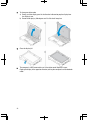
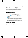
1
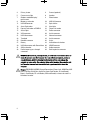
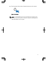
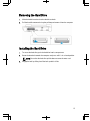
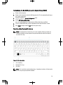
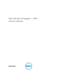
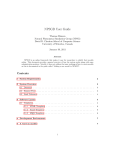
Dell Latitude 14 Rugged Extreme (7404)
Getting Started Guide
Regulatory Model: P45G
Regulatory Type: P45G001
Notes, Cautions, and Warnings
NOTE: A NOTE indicates important information that helps you make better use of your
computer.
CAUTION: A CAUTION indicates either potential damage to hardware or loss of data and
tells you how to avoid the problem.
WARNING: A WARNING indicates a potential for property damage, personal injury, or
death.
Copyright © 2014 Dell Inc. All rights reserved. This product is protected by U.S. and international copyright
and intellectual property laws. Dell™ and the Dell logo are trademarks of Dell Inc. in the United States
and/or other jurisdictions. All other marks and names mentioned herein may be trademarks of their
respective companies.
2014 - 02
Rev. A00
Contents
1 Finding Information and Resources........................................................ 5
2 System Overview........................................................................................7
3 Quick Setup................................................................................................. 9
4 Removing and Installing Components.................................................. 13
Opening the Press-Latch Doors...................................................................................... 13
Closing the Press-Latch Doors........................................................................................13
Removing the Battery......................................................................................................13
Installing the Battery....................................................................................................... 14
Removing the Hard Drive................................................................................................ 15
Installing the Hard Drive..................................................................................................15
5 Working on Your Computer.................................................................... 17
Using the Backlit Keyboard.............................................................................................17
Turning the Keyboard Backlight On/Off or Adjusting Brightness.............................18
Changing the Keyboard Backlight Color...................................................................18
Customizing the Backlit Keyboard in System Setup (BIOS)..................................... 19
Function <Fn> Key Lock Features.............................................................................19
Turning Stealth Mode On/Off.......................................................................................... 20
Disabling Stealth Mode in the System Setup (BIOS)...................................................... 20
Enabling and Disabling Wireless (WiFi) Feature.............................................................21
Converting Between Notebook and Tablet Modes ........................................................21
6 Quick Disconnect (QD) Connector........................................................ 23
Installing a QD connector................................................................................................23
Removing a QD connector.............................................................................................. 23
7 Specifications........................................................................................... 25
Information para NOM (únicamente para México).........................................................30
8 Contacting Dell......................................................................................... 33
1
Finding Information and Resources
See the safety and regulatory documents that shipped with your computer and the
regulatory compliance website at www.dell.com/regulatory_compliance for more
information on:
•
Safety best practices
•
Regulatory certification
•
Ergonomics
See www.dell.com for additional information on:
•
Warranty
•
Terms and Conditions (U.S. only)
•
End User License Agreement
Additional information on your product is available at www.dell.com/support/manuals
5
6
System Overview
2
7
3.
5.
7.
9.
11.
13.
15.
17.
19.
21.
23.
25.
27.
29.
31.
33.
Privacy shutter
Camera status light
Outdoor-readable display/
touchscreen
Memory-card reader
USB 3.0 Connector
Smart Card reader
ExpressCard reader or PCMCIA
Status lights
VGA connector
USB 2.0 connector
Touchpad
Network connector
Battery
USB 3.0 connector with PowerShare
SIM card reader
Radio frequency pass-through
connectors
4.
6.
8.
Camera (optional)
Speaker
Power button
10.
12.
14.
16.
18.
20.
22.
24.
26.
28.
30.
32.
34.
USB 2.0 Connector
Optical drive
Hard drive
Finger Print reader
Power connector
Serial connector
Network connector
Serial connector
Stylus
Sealed thermal chamber
HDMI Connector
Audio connector
Docking device connector
WARNING: Do not block, push objects into, or allow dust to accumulate in the air
vents. Do not store your Dell computer in a low-airflow environment, such as a
closed briefcase, while it is running. Restricting the airflow can damage the
computer or cause a fire. The computer turns on the fan when the computer gets
hot. Fan noise is normal and does not indicate a problem with the fan or the
computer.
Danger: EXPLOSION HAZARD-External Connections (Power Jack, HDMI Port, USB
Ports, RJ45 Port, RS232 Port, Audio Port, Smart Card Reader, SD card Reader,
Express Card Reader, PC-card Reader, SIM card Reader) are not to be used in a
Hazardous Location.
8
Quick Setup
3
WARNING: Before you begin any of the procedures in this section, read the safety
information that shipped with your computer. For additional best practices
information, see www.dell.com/regulatory_compliance
WARNING: The AC adapter works with electrical outlets worldwide. However,
power connectors and power strips vary among countries. Using an incompatible
cable or improperly connecting the cable to the power strip or electrical outlet
may cause fire or equipment damage.
CAUTION: When you disconnect the AC adapter cable from the computer, grasp
the connector, not the cable itself, and pull firmly but gently to avoid damaging the
cable. When you wrap the AC adapter cable, ensure that you follow the angle of
the connector on the AC adapter to avoid damaging the cable.
9
NOTE: Some devices may not be included if you did not order them.
1.
Connect the AC adapter to the AC adapter connector on the computer and to the
electrical outlet.
Figure 1. AC Adapter
2.
Connect the network cable (optional).
Figure 2. Network Connector
3.
Connect USB devices, such as a mouse or keyboard (optional).
Figure 3. USB Connector
4.
Connect IEEE 1394 devices, such as a 1394 hard drive (optional).
Figure 4. 1394 Connector
10
5.
Open the computer display and press the power button to turn on the computer.
Figure 5. Power Button
NOTE: It is recommended that you turn on and shut down your computer at least
once before you install any cards or connect the computer to a docking device or
other external device, such as a printer.
11
12
Removing and Installing
Components
4
This section provides detailed information on how to remove or install the components
from your computer.
Opening the Press-Latch Doors
There are eight press-latch doors. Four on the back, two on the right side, and two on the
left side of the computer.
1.
Left and right side press-latch doors: Slide the latch towards the back of the
computer to lock and towards the front to unlock.
2.
Back press-latch door: Slide the latch to the right to lock and to the left to unlock.
3.
The door can now be opened by pressing down on the latch and pulling the door in
a direction away from the computer.
Closing the Press-Latch Doors
1.
Rotate the door back in position, towards the computer.
2.
Engage the lock by sliding until the lock symbol is visible.
Removing the Battery
WARNING: Using an incompatible battery may increase the risk of fire or
explosion. Replace the battery only with a compatible battery purchased from Dell.
The battery is designed to work with your Dell computer. Do not use a battery from
other computers with your computer.
13
WARNING: Before removing or replacing the battery, turn off the computer,
disconnect the AC adapter from the electrical outlet and the computer, disconnect
the modem from the wall connector and computer, and remove any other external
cables from the computer.
WARNING: Not for use in hazardous locations. See installation instructions.
WARNING: To prevent ignition in a hazardous atmosphere, batteries must only be
changed or charged in an area known to be non-hazardous.
1.
Push the battery slide-lock to the right to unlock.
2.
The door can now be opened by sliding the latch down, and rotating the door in a
downward direction.
3.
To remove the battery:
a) To unlock, push the battery release latch to the right.
b) Slide the battery out of the computer by pulling on the tab attached to the
battery.
Installing the Battery
1.
Slide the battery into its slot until it clicks into place.
2.
Rotate the battery door back into its closed position and press until you can hear it
click in place.
3.
Engage the lock by pushing the latch to the left until the lock symbol is visible.
14
Removing the Hard Drive
1.
Slide the hard drive release latch to the left to unlock.
2.
Pull the hard drive outwards using the pull-loop and remove it from the computer.
Installing the Hard Drive
1.
To secure the hard drive, push the hard drive into its compartment.
2.
Rotate the door back towards the computer and press until it is in a closed position.
NOTE: Ensure that the hard drive pull tab does not cover the water seal.
3.
Engage the lock by sliding it until the lock symbol is visible.
15
16
Working on Your Computer
5
This section provides information about Backlit Keyboard, Stealth Mode, Function keys
and how to convert your computer to notebook and tablets modes.
Using the Backlit Keyboard
The Latitude rugged series comes equipped with a backlit keyboard that can be
customized. The backlight can be set to any of the following colors:
1.
White
2.
Red
3.
Green
4.
Blue
17
Turning the Keyboard Backlight On/Off or Adjusting Brightness
1.
Press <Fn> + < F10> to initialize the keyboard backlight switch.
NOTE: <Fn> key is not needed if function key <Fn> lock is activated.
NOTE: The first use of the above key combination turns on the backlight to its
lowest setting. Additional pressing of the key combinations cycle the
brightness settings through 25%, 50%,75% and 100% .
2.
Cycle through the key combination to either adjust the brightness or completely turn
off the keyboard backlight.
Changing the Keyboard Backlight Color
To change the keyboard backlight color:
1.
Press <FN> + < C> keys to cycle through the available backlight colors.
2.
White, Red, Green and Blue are active by default; up to two custom colors can be
added to the cycle in the System Setup (BIOS).
18
Customizing the Backlit Keyboard in System Setup (BIOS)
1.
Power off the computer.
2.
Power on the computer and at the Dell logo, tap the <F2> key repeatedly to bring up
the system setup menu.
3.
Expand and open the System Configuration menu.
4.
Select RGB Keyboard Backlight.
5.
To set a custom RGB value, use the input boxes on the right side of the screen.
6.
Click Apply changes and click Exit close the system setup.
You can enable/disable the standard colors (White, Red, Green and Blue).
Function <Fn> Key Lock Features
NOTE: The keyboard has Function key <Fn> lock capability. When activated, the
secondary functions on the top row of keys become default and will not require
use of the <Fn> key.
Figure 6. <Fn> key callouts
1.
<Fn> Lock Key
2.
Affected <Fn> keys
3.
<Fn> Key
NOTE: <Fn> Lock affects only the above keys . Secondary functions will not require
the <Fn> key to be pressed while enabled.
19
Activating the Function (Fn) lock
1.
Press the <Fn> + <Esc> keys
NOTE: Other secondary functions on keys below the top row are not affected
and requires the use of the <Fn> key.
2.
Press the <Fn> + <Esc> keys again to deactivate the function lock feature.
The function keys return to their default actions.
Turning Stealth Mode On/Off
1.
Press the <Fn> + <F7> key combination (<Fn> key not needed if Fn lock is activated)
to turn on stealth mode.
NOTE: Stealth mode is a secondary function of the <F7> key. The key can be
used to perform other functions on the computer when not used with the <Fn>
key to activate stealth mode.
2.
All the lights and sounds are turned off.
3.
Press the <Fn> + <F7> key combination again to turn off the stealth mode.
Disabling Stealth Mode in the System Setup
(BIOS)
1.
Power off the computer.
2.
Power on the computer and at the Dell logo, tap the <F2> key repeatedly to bring up
the System Setup menu.
3.
Expand and open the System Configuration menu.
20
4.
Select Stealth Mode Control.
NOTE: Stealth mode is enabled by default.
5.
Select Disable to disable the stealth mode.
6.
When complete, Apply changes and Exit the BIOS or system setup.
Enabling and Disabling Wireless (WiFi) Feature
1.
Press the <Fn> + <PrtScr> keys to enable wireless networking.
2.
Press the<Fn> + < PrtScr> keys again to disable wireless networking.
Converting Between Notebook and Tablet Modes
1.
To undock the computer, press the display latch.
2.
Open the display lid by lifting it upwards.
21
3.
To change to tablet mode:
a) Gently push the display panel in the direction indicated to pop the display from
the display frame.
b) Rotate the display by 180–degrees until it clicks back into place.
4.
Close the display lid.
5.
The computer is now converted for use in the tablet mode. Repeat the steps,
flipping the display in the opposite direction, to bring the computer back to notebook
mode.
22
Quick Disconnect (QD) Connector
6
Latitude fully rugged products come equipped with receptacles for QD (QuickDisconnect) connectors at the corners. These receptacles allow the connection of
optional accessories such as shoulder straps.
Installing a QD connector
1.
Perform the following steps to install a QD connector:
a) Align the QD connector to the receptacle on the corner of the computer.
b) Press and hold the button on top of the QD connector.
2.
Insert the connector into the receptacle while holding the button pressed.
3.
Release the button after the connector is seated in the receptacle to secure it.
Removing a QD connector
1.
Press and hold the button on top of the QD connector.
2.
Pull the connector out of the receptacle while holding the button pressed.
23
24
7
Specifications
NOTE: Offerings may vary by region.
Table 1. System Information
Feature
Specification
DRAM bus width
64 bit
Flash EPROM
SPI 32Mbits
PCIe 2.0 bus
100MHz
Table 2. Processor
Feature
Specification
Types
Intel Core i3/i5/i7 series
L3 cache
up to 4MB
External bus frequency
1600MHz
Table 3. Memory
Feature
Specification
Memory connector
two SODIMM slots
Memory capacity
2GB, 4GB, or 8GB
Memory type
DDR3L SDRAM 1600 Mhz
Minimum memory
4GB
Maximum memory
16GB
25
Table 4. Audio
Feature
Specification
Type
four-channel high definition audio
Controller
Realtek ALC3226
Stereo conversion
24 bit (analog-to-digital and digital-to-analog)
Interface:
Internal
HD audio
External
microphone-in/stereo headphones/external
speakers connector
Speakers
one mono speaker
Internal speaker amplifier
2 W (RMS)
Volume controls
Volume Up/Volume Down buttons
CAUTION: Adjustment of volume control, as well as the equalizer in the operating
system and/or equalizer software, to other settings than the center position may
increase the earphones and/or headphones output and cause hearing damage or
loss.
Table 5. Video
Feature
Specification
Type
integrated on system board
Controller
UMA
Discr
ete
(optio
nal)
26
Intel Core i3 / i5 series
Intel HD Graphics 4400
Intel Core i7
Intel HD Graphics 5000
Nvidia GeForce (N14M-GE) Discrete Graphics
Card, 2GB Graphics
Table 6. Communications
Feature
Specification
Network adapter
10/100/1000 Mb/s Ethernet (RJ-45)
Wireless
•
•
WLAN with Bluetooth enabled
WWAN
Table 7. Ports and Connectors
Feature
Specification
Audio
one microphone/stereo headphone/speakers
connector
Video
•
•
Network adapter
two RJ-45 connectors
USB 2.0
two 4–pin USB 2.0–compliant connector
USB 3.0
one 4-pin USB 3.0-compliant connector with
PowerShare
one 15-pin VGA connector
one 19-pin HDMI connector
one 4-pin USB 3.0-compliant connector
Memory card reader
one ExpressCard Reader or optional PCMCIA
Reader (replaces ExpressCard Reader)
Serial
two DB9 pin serial connectors
Docking port
one
SIM Slot
one micro-SIM slot with security feature
Table 8. Display
Feature
Specification
Type
WLED display
Size
14.0 inches
Dimensions:
Height
190.00 mm (7.48 inches)
27
Feature
Specification
Width
323.5 mm (12.59 inches)
Diagonal
375.2 mm (14.77 inches)
Active area (X/Y)
309.4 mm x 173.95 mm
Maximum resolution
1366 x 768 pixels
Operating angle
0° (closed) to 180°
Refresh rate
60 Hz
Minimum Viewing angles:
Horizontal
+/- 70° minimum for HD
Vertical
+/- 70° minimum for HD
Pixel pitch
0.1875 mm
Table 9. Keyboard
Feature
Specification
Number of keys
83 keys: US English, Thai, French-Canadian,
Korean, Russian, Hebrew, English-International
84 keys: UK English, French Canadian Quebec,
German, French, Spanish (Latin America),
Nordic, Arabic, Canada Bilingual
85 keys: Brazilian Portuguese
87 keys: Japanese
Layout
QWERTY/AZERTY/Kanji
Table 10. Touchpad
Feature
Specification
Active Area:
28
X-axis
91 mm (3.58 inches)
Y-axis
51 mm (2.00 inches)
Table 11. Battery
Feature
Specification
Type
6–cell or 9–cell “smart” lithium ion
Dimensions:
Height
21 mm (0.82 inches)
Width
166.9 mm (6.57 inches)
Depth
80 mm (3.14 inches)
Weight
•
•
Voltage
6–cell : 365.5 g (0.80 lbs)
9–cell : 520 g (1.14 lbs)
14.8 VDC
Temperature range:
Operating
•
•
Non-Operating
–51 °C to 71 °C (–60 °F to 160 °F)
Charging : 0 °C to 60 °C (32 °F to 140 °F)
Discharging: 0 °C to 70 °C (32 °F to 158 °F)
NOTE: The battery pack is capable of safely withstanding the above storage
temperatures with 100% charge.
NOTE: The battery pack is also capable of withstanding storage temperatures
from –20 °C to +60 °C with no degradation in its performance.
Coin-cell battery
3 V CR2032 lithium—ion coin cell
Table 12. AC Adapter
Feature
Specification
Type
65 W/90 W
Input voltage
100 VAC to 240 VAC
Input current (maximum)
1.5 A/1.7 A
Input frequency
50 Hz to 60 Hz
Output power
65 W
Output current
3.34 A/4.62 A(continuous)
29
Rated output voltage
19.5 +/– 1.0 VDC
Temperature range:
Operating
0 °C to 40 °C (32 °F to 104 °F)
Non-Operating
–40 °C to 70 °C (–40 °F to 158 °F)
Table 13. Physical
Feature
Specification
Height
51.5 mm (2.02 inches)
Width
356.1 mm (14.01 inches)
Depth
247.5 mm (9.74 inches)
Weight
8.4 lbs (3.81 kg)
Table 14. Environmental
Feature
Specification
Temperature:
Operating
—29 °C to 63 °C (—20 °F to 145 °F)
Storage
–51 °C to 71 °C (–60 °F to 160 °F)
Relative humidity (maximum):
Operating
10 % to 90 % (non condensing)
Storage
0 % to 95 % (non condensing)
Altitude (maximum):
Operating
–15.24 m to 4572 (–50 ft to 15,000 ft ft)
Non-Operating
–15.24 m to 9144 m (–50 ft to 30,000 ft)
Airborne contaminant level
G1 as defined by ISA-71.04–1985
Information para NOM (únicamente para México)
The following information is provided on the device described in this document in
compliance with the requirements of the official Mexican standards (NOM).
30
Voltaje de alimentación
100 VAC – 240 VAC
Frecuencia
50 Hz – 60 Hz
Consumo eléctrico
1,5 A/1,7 A
Voltaje de salida
19,50 V de CC
Intensidad de salida
3,34 A/4,62 A
31
32
Contacting Dell
8
NOTE: If you do not have an active Internet connection, you can find contact
information on your purchase invoice, packing slip, bill, or Dell product catalog.
Dell provides several online and telephone-based support and service options.
Availability varies by country and product, and some services may not be available in
your area. To contact Dell for sales, technical support, or customer service issues:
1.
Visit dell.com/support
2.
Select your support category.
3.
Verify your country or region in the Choose a Country/Region drop-down menu at
the top of page.
4.
Select the appropriate service or support link based on your need.
33