1
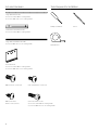
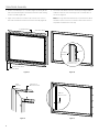
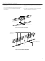
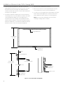
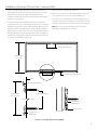
INSTRUCTION BOOK FOR
UTB Contour
Included Hardware
Tools Required for Installation
Large Wall Bracket (47”)
(1) Screens under 104" in viewing width
(2) Screens 104" and over in viewing width
Phillips Screwdriver
Small Bottom Wall bracket (8”)
(1) Screens under 104" in viewing width
Large Bottom Wall bracket (44”)
(1) Screens 104" and over in viewing width
Tape Measure
Frame Brackets
(1) Screens under 104" in viewing width
(2) Screens 104" and over in viewing width
#10 X 3/8" Silver Screws (12)
8-32 X 3/8" Machine Screws (4)
#10 X 3/8" Pointed
Black Screws (Varies)
8–32 X 1/2" Fillister Screw
(1) Screens under 104" in viewing width
(2) Screens 104" and over in viewing width
2
Pencil
Inner Frame & Viewing Surface Assembly
1. Create a clean work area for assembly using a soft clean material.
This will protect the inner frame and ensure a clean projection
surface.
2. Unwrap frame pieces. Assemble inner frame pieces on the work
area.
3. Slide inner frame pieces together at corners. Secure inner frame
pieces with (12) #10 x 3/8" silver screws (Figure 1).
4. Set the assembled inner frame aside. Unroll screen surface and
place it viewing side down on the clean work area.
6. Wrap fabric around inner frame and hook grommets over the
corner pins (Figure 2).
7. Hook the rest of the grommets over the flat head screws on all
sides (Figure 2). Please be sure the grommets clear the head of
each screw.
Note: Your screen was assembled and aligned prior to shipment.
If any realignment is necessary, the positioning of the flat head
screws can be adjusted. Using a Phillips screwdriver, rotate the
flat head screw one turn counterclockwise. Reposition screw as
needed. Secure the screw in place by slowly rotating it clockwise.
5. Place inner frame on screen surface, screw side up.
Grommets
Corner
Pin
(12) #10 x 3/8" Screws.
Silver, Flat Tip
Grommet is under
the Flat Head Screw
Flat Head
Screw
Figure 1
Figure 2
3
Outer Bezel Assembly
1. Position outer bezel pieces on all sides (Figure 3a). Gently lift and
slide each outer bezel piece around the inner frame and viewing
surface assembly (Figure 3b).
3. Secure the outer bezel to the inner frame by inserting the #10 x
3/8" black screws into each of the large holes on all four sides of
the screen (Figure 5).
2. Align corners and insert one 8–32 x 3/8" screw in each corner to
attach the outer bezel onto the inner frame assembly (Figure 4).
Top Outer Bezel
Note: The long outer bezel side with (2) or (4) small holes will be
the bottom of the screen. Do not insert screws in these holes as
they will be needed for the next step.
Side Outer Bezel
Bezel
Viewing
Surface
Side View of Screen
with Bezel in Place
Bottom Outer Bezel
Side Outer Bezel
Figure 3b
Figure 3a
Align
Corners
(4) 8–32 x 3/8"
Machine Screws
#10 x 3/8"
Black Screws
Figure 4
4
Figure 5
Outer Bezel Assembly (continued)
4. Depending on the size of your screen, you will have one or two
frame brackets.
a. For screens under 104” wide viewable, attach (1) frame bracket
to the bottom of the screen with (2) #10 x 3/8" pointed BLACK
screws (Figure 6).
b. For screens 104” wide viewable and over, attach (2) frame
brackets If your screen is 104" or over in viewing area width
(Figure 7).
5. Insert 8-32 x 1/2" zinc plated fillister screw into frame bracket(s)
(Figure 6 or 7). Rotate four or five turns only.
(2) #10 X 3/8" Pointed
Black Screws
Frame Bracket
8–32 X 1/2" Fillister Screw
Figure 6 — Screens Under 104" in Viewing Width
(4) #10 X 3/8" Pointed
Black Screws
8–32 X 1/2" Fillister Screw
Figure 7 — Screens 104" and Over in Viewing Width
5
Installation of Screens Under 104" in Viewing Width
1. Secure the large top wall bracket to wall studs at the desired
height. Make sure the bracket is level. The top of the screen will
be 2–1/4" above the top of the edge of this wall bracket when
mounted. You will need at least a 3" clearance above the bracket
to hang the screen (Figure 8).
2. To install the small bottom wall bracket, you must measure the
overall height of the screen and subtract 3". Find the center point
of the top wall bracket. Using your screen height minus 3”,
measure down from the top edge of the top wall bracket and
mark the wall. This will be the center point of the bottom edge of
the bottom wall bracket. Level the bottom wall bracket and mark
the wall for the two screw holes in this bracket (Figure 8).
3. Attach the bottom wall bracket to the wall.
4. Lift the screen at least 3" over the top wall bracket. Lower the
screen until the frame hooks onto the top wall bracket.
5. To secure your screen against wall, locate the fillister screw in the
bottom frame bracket. Tighten the screw until it touches the
bottom wall bracket, then rotate two more turns (Figure 8).
Note: This screw can be rotated up to three more turns if
stretching of viewing surface is needed.
Large Wall Bracket
Overall Height
of Screen
Small Bottom
Wall Bracket
Wall
Large Wall Bracket
Overall Height
of Screen Less 3"
Screws Not Provided
Small Bottom
Wall Bracket
Fillister Screw
Small Bottom
Wall Bracket
Figure 8 — Screens Under 104" in Viewing Width
6
Installation of Screens 104" and Over in Viewing Width
1. Secure the (2) large top wall bracket to wall studs at the desired
height. Make sure the brackets are level. The top of the screen will
be 2–1/4" above the top of the edge of this wall bracket when
mounted. You will need at least a 3" clearance above the brackets to
hang the screen (Figure 9).
2. To install the large bottom wall bracket, you must measure the
overall height of the screen and subtract 3". Draw a line on your wall
between the top edges of the two top wall brackets. Mark the center
point between the top wall brackets on this line. Using your screen
height minus 3”, measure down from this center point and mark the
wall. This will be the center point of the bottom edge of the bottom
wall bracket. Level the bottom wall bracket and mark the wall for the
six screw holes in this bracket (Figure 9).
3. Attach the bottom wall bracket to the wall.
4. Lift the screen at least 3" over the top wall brackets. Lower the
screen until the frame hooks onto the top wall brackets.
5. To secure your screen against wall, locate the fillister screws in
the bottom frame brackets. Tighten the screws until they touch
the bottom wall bracket, then rotate two more turns (Figure 9).
Note: This screw can be rotated up to three more turns if
stretching of viewing surface is needed.
(2) Large Wall Brackets
Overall Height
of Screen
8"
Large Bottom Wall Bracket
Wall
(2) Large Wall Brackets
Overall Height
of Screen Less 3"
Screws Not Provided
Large Bottom
Wall Bracket
Fillister Screw
Large Bottom
Wall Bracket
Figure 9 — Screens 104" and Over in Viewing Width
7
LIMITED ONE YEAR WARRANTY ON DA-LITE PRESENTATION PRODUCTS
Milestone AV Technologies LLC warrants certain Da-Lite branded products to the original purchaser only, to be free from defects
in materials and workmanship for a period of one (1) year from the date of purchase by the original purchaser; provided they are
properly operated according to Da-Lite’s instructions and are not damaged due to improper handling or treatment after shipment
from the factory.
This warranty does not apply to equipment showing evidence of misuse, abuse or accidental damage, or which has been tampered
with or repaired by a person other than authorized Da‑Lite personnel.
Da-Lite’s sole obligation under this warranty shall be to repair or to replace (at Da-Lite’s option) the defective part of the merchandise.
Returns for service should be made to your Da-Lite dealer. If it is necessary for the dealer to return the screen or part to Da-Lite,
transportation expenses to and from Da-Lite are payable by the purchaser and Da-Lite is not responsible for damage in shipment.
To protect yourself against damage or loss in transit, insure the product and prepay all transportation expenses.
TO THE MAXIMUM EXTENT PERMITTED BY APPLICABLE LAW, THIS WARRANTY IS IN LIEU OF ALL OTHER WARRANTIES,
EXPRESS OR IMPLIED, INCLUDING WARRANTIES AS TO FITNESS FOR USE AND MERCHANTABILITY. Any implied warranties of
fitness for use, or merchantability, that may be mandated by statute or rule of law are limited to the one (1) year warranty period.
This warranty gives you specific legal rights, and you may also have other rights, which vary from state-to-state. TO THE MAXIMUM
EXTENT PERMITTED BY APPLICABLE LAW, NO LIABILITY IS ASSUMED FOR EXPENSES OR DAMAGES RESULTING FROM
INTERRUPTION IN OPERATION OF EQUIPMENT, OR FOR INCIDENTAL, DIRECT, OR CONSEQUENTIAL DAMAGES OF ANY NATURE.
In the event that there is a defect in materials or workmanship of a Da-Lite product, you may contact our Sales Partners at PO Box 137,
Warsaw, IN 46581-0137, (574) 267-8101, (800) 622-3737.
IMPORTANT: THIS WARRANTY SHALL NOT BE VALID AND DA-LITE BRANDED PRODUCTS SHALL NOT BE BOUND BY THIS
WARRANTY IF THE PRODUCT IS NOT OPERATED IN ACCORDANCE WITH THE DA-LITE WRITTEN INSTRUCTIONS.
Keep your sales receipt to prove the date of purchase and your original ownership.
A Milestone AV Technologies Brand
3100 North Detroit Street
Warsaw, Indiana 46582
P: 574.267.8101 or 800.622.3737
F: 574.267.7804 or 877.325.4832
E: [email protected]
www.da-lite.com
DL–0142 (Rev. 2) 11.13
© 2013 Milestone AV Technologies LLC. Printed in U.S.A.
23568