1
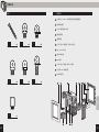
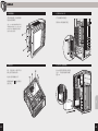
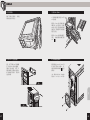
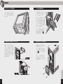
CARBIDE
SERIES®
SPEC-01
MID-TOWER GAMING CASE
INSTALLATION GUIDE / GUIDE D'INSTALLATION
INSTALLATIONSHANDBUCH / GUIDA DI INSTALLAZIONE
GUÍA DE INSTALACIÓN / РУКОВОДСТВО ПО УСТАНОВКЕ /
安装指南 / インストールガイド
English:..................................................................................................................... 1-10
Français:.................................................................................................................11-20
Italiano:...................................................................................................................21-30
Deutsch:.................................................................................................................31-40
Español:..................................................................................................................41-50
Россию:....................................................................................................................51-60
中文:..........................................................................................................................61-70
日本語:......................................................................................................................71-80
SPEC-01
Table of Contents
Case Specifications
ENGLISH
Congratulations:...........................................................................................................................................................1
Case specifications:....................................................................................................................................................2
Accessory kit contents:.............................................................................................................................................3
Case features:................................................................................................................................................................4
Removing the side panels:.......................................................................................................................................5
Installing the motherboard:.....................................................................................................................................5
Installing PCI-E/PCI card(s):...................................................................................................................................6
Installing the PSU:........................................................................................................................................................6
Length:....................................................................................................... 447mm
Removing the front fascia:.......................................................................................................................................7
Installing an ODD:........................................................................................................................................................7
Width:........................................................................................................ 200mm
Installing SSDs and HDDs:........................................................................................................................................8
Height:....................................................................................................... 428mm
Installing a second front fan:..................................................................................................................................8
Weight:.......................................................................................................... 4.8kg
Powering the case fans:.............................................................................................................................................9
Installing the front I/O connectors:.....................................................................................................................9
Frequently asked questions:.................................................................................................................................10
Maximum GPU length:
Top slots:................................................................................................... 414mm
Lower slots:.............................................................................................. 275mm
Congratulations!
Maximum CPU cooler height:.......................................................... 150mm
Thank you for purchasing a
Carbide Series® SPEC-01 Mid-Tower PC Case.
1
447mm
200mm
428mm
Carbide Series SPEC-01 is proof that great looks,
smart design, and durable construction don’t
need to be pricy, and that basic doesn’t need to
be boring. You get aggressive styling, a huge side
panel window for admiring your components,
and an LED-lit front intake fan that draws cool air
directly to your graphics cards.
Inside, there’s room for up to five fans, and the four
combination hard drive/SSD trays make storage
installation and upgrades quick and easy. Cable
routing cutouts help you reduce clutter, and the
built-in dust filters help protect your components.
Up front, the USB 3.0 connector gets you up to
speed with the latest high-performance storage
devices.
Maximum PSU length:......................................................................... 230mm
2
SPEC-01
Accessory Kit Contents
x4
x10
MBD/HDD screws
Cable ties
d
b
x4
e
Short fan screws
SSD pan h
ead
screws
c
x16
A
I/O Panel (x2 USB 3.0, Headphone/ Mic, and Power/ Reset)
B
Removable front fascia
C
x2 Tool-free removable ODD covers
D
Windowed side panel
E
Solid side panel
F
x4 Tool-free 3.5" hardrive trays with 2.5" compatibility
G
3-pin 120mm LED Fan
H
Bottom PSU dust filter
I
PCI-E screw rail
J
x4 Tool-free 3.5" hardrive cages with 2.5" compatibility
K
x2 Top 120mm fan mounts
L
CPU backplate cutout
SSD/ODD screws
x16
f
ENGLISH
a
Case Features
x4
Long fan screws
L
g
x1
Motherboard
standoff
L
3
4
SPEC-01
STEP 02
3. Installing PCI-E/PCI Card(s)
Simply remove the
thumbscrews then slide the
side panels back and out.
emove thumbscrews and
R
corresponding slot cover(s).
Install the add-on card and
secure with thumbscrews.
STEP
Note: Corsair recommends
removing both side panels and
setting them aside when building
your system to avoid accidental
damage. Both side panels are
interchangeable and should be
removed to reduce clutter.
STEP 04
STEP 03
02
STEP 04
2. Installing the Motherboard
4. Installing the PSU (Power Supply Unit)
First, install your
motherboard’s I/O shield (see
your motherboard’s manual
for guidance).
Position the PSU on the
bottom of the case then align
the caseholes and secure the
PSU with screws provided with
your power supply.
lign your motherboard with
A
the pre-installed standoffs.
Use the provided screws
to secure the
motherboard to the
motherboard tray.
5
ENGLISH
1. Removing the Side Panels
b
6
STEP 07
05
P
STE the Front Fascia
5. Removing
SPEC-01
7. Installing SSDs and HDDs
The four included drive trays
support both 3.5" and 2.5"
devices.
ENGLISH
To remove the front fascia
(front panel),grasp the tab
located at the bottom fascia
and pull outward.
o install a 3.5" HDD, pull the
T
drive tray from each side to
extend the mounting points.
Next, place your HDD onto
the tray and push the drive
back to a close. No screws are
necessary to secure the drive
onto the tray.
STEP 06
STEP 08
To install a 2.5" SSD, place the
drive on the tray and use the
provided screws c to install
the SSD.
STEP 06
6. Installing an ODD (Optical Disk Drive)
8. Installing a Second Front Fan
First, remove the front panel
5.25" drive bay cover then
slide the ODD into the drive
bay until the tool-free latch
clicks, securing the drive. To
release an optical drive, push
in the tool-free tab then pull
the drive outward.
To install an additional 120mm
or 140mm fan, remove the
front fascia (step 5)then use
the provided long fan screws f
to mount the new fan.
First
Note: To maximize airflow you
may install either x2 120mm or
x2 140mm fans in the front of the
chassis.
Second
7
8
SPEC-01
Frequently Asked Questions
After locating your 3 or 4
pin fan headers on your
motherboard (see your
motherboard’s manual for fan
header locations), plug in the
included fan cable.
1. How do I remove the I/O Panel?
If needed, you can uninstall your I/O panel by removing the front
fascia (step 5) then unscrewing the 2 screws at each side of
panel. (drawing)
ENGLISH
9. Powering the Case Fans
2. Does the polarity matter with the I/O panel’s power and reset
header?
No, only the LED headers.
10. Installing the Front I/O Connectors
3. W
ho should I contact if I received my case damaged or one of the
fans is no longer working?
Please go to corsair.force.com and request an RMA
so that we can replace the damaged part(s).
See your motherboard’s
manual for front panel header
locations and pin-outs.
USB 3.0
4. Where can I mount a fan?
USB 2.0
POWER SW
HD AUDIO
HDD LED
RESET SW
Fan Mount Locations
POWER LED –
POWER LED +
Front
x2 120mm or x2 140mm
Top
x2 120mm
Rear
120mm
Bottom
x
Side
x
Mid
x
To learn more about this case visit the product page at corsair.com
9
10
SPEC-01
Table des matières
Spécifications du boîtier
Félicitations:.................................................................................................................................................................11
Spécifications du boîtier:........................................................................................................................................12
Contenu du kit d’accessoires:...............................................................................................................................13
FRANÇAIS
Attributs du boîtier:..................................................................................................................................................14
Retrait des panneaux latéraux:............................................................................................................................15
Installation des cartes PCI-E/PCI:.......................................................................................................................15
Installation de la carte mère:................................................................................................................................16
Installation du bloc d’alimentation:...................................................................................................................16
Longueur:................................................................................................. 447mm
Retrait de la façade:..................................................................................................................................................17
Installation d’un lecteur de disque optique:..................................................................................................17
Largeur:..................................................................................................... 200mm
Installation de disques SSD et de lecteurs de disques durs:...................................................................18
Hauteur:..................................................................................................... 428mm
Installation d’un deuxième ventilateur avant:...............................................................................................18
Poids:.............................................................................................................. 4.8kg
Alimentation des ventilateurs du boîtier:........................................................................................................19
Installation des connecteurs E/S avant:...........................................................................................................19
Foire aux questions:..................................................................................................................................................20
Longueur maximale du processeur graphique:
Emplacements supérieurs:................................................................. 414mm
Emplacements inférieurs:................................................................... 275mm
Félicitations !
Hauteur maximale du refroidisseur de processeur:............... 150mm
Nous vous remercions d’avoir acheté un
boîtier d’ordinateur mi-tour.
11
447mm
200mm
428mm
La gamme Carbide SPEC-01 est la preuve que
look, design et durabilité ne riment pas forcément
avec hors de prix, et que basique ne se traduit pas
nécessairement par monotone. Vous profitez d’un
style incisif, d’une grande fenêtre latérale pour
mieux admirer vos composants et d’un ventilateur
aspirant illuminé par DEL à l’avant qui refroidit
directement vos cartes graphiques.
À l’intérieur, de la place pour cinq ventilateurs, et
les quatre plateaux de combinaison disque dur/
SSD font de l’installation et des mises à niveau un
jeu d’enfants. Les découpages pour câble limitent
le désordre, et les filtres à poussière intégrés
protègent vos composants. À l’avant, le connecteur
USB 3.0 vous branche aux derniers périphériques
de stockage haute performance.
Longueur maximale du bloc d’alimentation:............................ 230mm
12
SPEC-01
Contenu du kit d’accessoires
x4
attache-câbles
d
x4
vis à tête cylindrique
bombée pour SSD
b
x10
vis pour MBD/HDD
e
vis courtes pour
ventilateur
x16
c
x16
vis pour SSD/
Disque optique
f
A
Panneau E/S (x2 USB 3.0, Casque/Mic, et Alimentation/Réinitialisation)
B
Façade amovible
C
x2 caches pour lecteurs optiques amovibles sans outils
D
Panneau latéral à fenêtre
E
Panneau latéral normal
F
x4 plateaux pour disque dur 3,5 pouces, sans outils, avec compatibilité 2,5 pouces
G
Ventilateur DEL à trois broches de 120 mm
H
Filtre à poussière pour bloc d’alimentation inférieur
I
Rail à vis pour PCI-E
J
x4 cages pour disque dur 3,5 pouces, sans outils, avec compatibilité 2,5 pouces
K
x2 fixations supérieures pour ventilateur de 120 mm
L
Découpage dans la plaque arrière du processeur
FRANÇAIS
a
Attributs du boîtier
x4
vis longues pour
ventilateur
L
g
x1
entretoise pour carte
mère
L
13
14
SPEC-01
STEP 02
1. Retrait des panneaux latéraux
3. Installation des cartes PCI-E/PCI
Retirez simplement les vis
de serrage et faites glisser
les panneaux latéraux vers
l’arrière pour les sortir.
etirez les vis de serrage et
R
le(s) cache(s) d’emplacement
correspondant(s).
STEP 04
STEP 03
02
FRANÇAIS
STEP
Installez la carte
complémentaire et fixez-la
avec les vis.
Remarque : Corsair recommande
de retirer les deux panneaux
latéraux et de les mettre de
côté lors de la construction de
votre système, afin d’éviter tout
endommagement accidentel. Il est
recommandé d’enlever ces deux
panneaux interchangeables pour
créer plus de place.
STEP 04
2. Installation de la carte mère
4. Installation du bloc d’alimentation
Tout d’abord, installez le
blindage d’E/S de la carte
mère (reportez-vous au
manuel d’instructions de la
carte mère).
Positionnez le bloc
d’alimentation en bas du
boîtier, alignez-le avec les
trouset fixez-le à l’aide des vis
accompagnant le bloc.
lignez la carte mère avec les
A
entretoises préinstallées.
Servez-vous des vis fournies
pour fixer la carte mère au
plateau.
15
b
16
STEP 07
05
P
STEde la façade
5. Retrait
7. Installation de disques SSD et de lecteurs de disques durs
Pour retirer la façade
(panneau avant),
tirez sur la languette située en
bas de la façade.
Les quatre plateaux
inclus prennent en charge
indifféremment les disques 3,5
et 2,5 pouces.
SPEC-01
STEP 06
FRANÇAIS
our installer un disque dur
P
3,5 po, tirez sur les deux côtés
du plateau pour agrandir les
points de montage. Ensuite,
placez le disque dur dans le
plateau et repoussez le disque
pour fermer. Il n’y a pas besoin
de vis pour fixer le disque sur
le plateau.
STEP 08
Pour installer un SDD de
2,5 po, placez le disque sur le
plateau et servez-vous des
vis c fournies pour le fixer.
STEP 06
6. Installation d’un lecteur de disque optique
8. Installation d’un deuxième ventilateur avant
Tout d’abord, retirez le cache
de la baie de 5,25 pouces du
panneau avant, puis faites
glisser le lecteur optique dans
le logement jusqu’à ce que le
loquet s’enclenche.
Pour faire sortir un lecteur de
disque optique, appuyez sur
la languette, puis tirez sur le
lecteur (pas besoin d’outils).
Pour installer un ventilateur
de 120 mm ou 140 mm
complémentaire, retirez la
façade (étape 5), puis servezvous des longues vis f
pour poser le nouveau
ventilateur.
Première
Remarque : pour maximiser le
débit d’air, vous pouvez installer
deux ventilateurs soit de 120 mm,
soit de 140 mm sur le devant du
châssis.
Deuxième
17
18
SPEC-01
Foire aux questions
Après avoir repéré les cavaliers
à 3 ou 4 broches situés sur
la carte mère (consultez le
manuel de la carte mère
pour l’emplacement des
cavaliers), branchez le câble
de ventilateur fourni.
1. Comment retirer le panneau d’E/S ?
Si besoin est, vous pouvez démonter le panneau d’E/S en retirant la
façade (étape 5) et en dévissant les deux vis situées de chaque côté.
FRANÇAIS
9. Alimentation des ventilateurs du boîtier
2. La polarité est-elle importante avec l’alimentation du panneau d’E/S
et le cavalier de réinitialisation ?
Non, uniquement avec les cavaliers de DEL.
10. Installation des connecteurs E/S avant
3. À
qui dois-je m’adresser si mon boîtier est endommagé à l’arrivée ou
lorsqu’un ventilateur ne fonctionne plus ?
Veuillez vous rendre sur corsair.force.com et demandez un RMA
(Autorisation de retour de marchandise) pour que nous puissions
remplacer la ou les pièces endommagées.
Consultez le manuel de la carte mère pour plus
d’informations sur l’emplacement des cavaliers
et des broches de sortie.
USB 3.0
4. Où puis-je monter un ventilateur ?
USB 2.0
POWER SW
HD AUDIO
HDD LED
RESET SW
POWER LED –
POWER LED +
Montage pour ventilateur Emplacements
Avant
x2 120mm or x2 140mm
Haut
x2 120mm
Arrière
120mm
Bas
x
Côté
x
Milieu
x
Pour en savoir plus sur ce boîtier, veuillez vous rendre sur corsair.com à
la page des produits.
19
20
SPEC-01
Sommario
Specifiche case
Congratulazioni:.........................................................................................................................................................21
Specifiche case:..........................................................................................................................................................22
Contenuto kit di accessori:....................................................................................................................................23
Caratteristiche case:.................................................................................................................................................24
Rimozione dei pannelli laterali:...........................................................................................................................25
Installazione delle schede PCI-E/PCI:..............................................................................................................25
Installazione della scheda madre:......................................................................................................................26
Installazione dell’unità di alimentazione:........................................................................................................26
Lunghezza:............................................................................................... 447mm
Installazione di un’unità ODD:..............................................................................................................................27
Profondità:............................................................................................... 200mm
Installazione unità SSD e HDD:............................................................................................................................28
Altezza:...................................................................................................... 428mm
Installazione di una seconda ventola frontale:..............................................................................................28
ITALIANO
Rimozione del frontale:...........................................................................................................................................27
Peso:............................................................................................................... 4.8kg
Alimentazione ventole del case:.........................................................................................................................29
Installazione dei connettori di I/O frontali:....................................................................................................29
Domande più frequenti:..........................................................................................................................................30
Lunghezza massima GPU:
Slot superiori:.......................................................................................... 414mm
Slot inferiori:............................................................................................. 275mm
Congratulazioni!
Altezza massima raffreddatore CPU: 150mm:......................... 150mm
Grazie per aver acquistato un case mid-tower
per PC Carbide Series® SPEC-01.
21
447mm
200mm
428mm
Il Carbide Series SPEC-01 è la prova che un look elegante,
un design intelligente ed una struttura resistente non
devono necessariamente essere costosi e che la semplicità
non è detto che sia noiosa. Il pacchetto comprende uno
stile grintoso, un’enorme finestra sul pannello laterale
per poter ammirare i componenti interni ed una ventola
d’aspirazione frontale con illuminazione a LED che soffia
aria fresca direttamente sulle schede grafiche.
All’interno c’è spazio sufficiente per cinque ventole, e i
quattro vani con combinazione disco rigido/SSD rendono
l’installazione e l’aggiornamento delle memorie semplici
e rapidi. Gli intagli di instradamento dei cavi ti aiutano
a ridurre l’ingombro interno e i filtri antipolvere integrati
garantiscono una protezione per i componenti interni.
Sulla parte frontale, il connettore USB 3.0 garantisce una
velocità ad altissime prestazioni dei dispositivi di storage.
Lunghezza massima PSU: 230mm:................................................ 230mm
22
SPEC-01
Contenuto kit di accessori
x4
x10
viti per scheda
madre/unità HDD
fascette per cavi
d
b
x4
viti a testa piatta per
unità SSD
e
x16
viti corte per ventola
c
x16
viti per unità SSD/
ODD
f
A
Pannello I/O (2 prese USB 3.0, cuffie/microfono, alimentazione/Reset)
B
Frontale rimovibile
C
2 coperture per unità ODD rimovibili
D
Pannello laterale con finestra
E
Pannello laterale senza finestra
F
4 vani unità disco rigido 3,5 pollici senza viti con compatibilità per unità 2,5 pollici
G
Ventola LED da 120mm a 3 pin
H
Filtro antipolvere inferiore per unità di alimentazione
I
Guida viti PCI-E
J
4 vani unità disco rigido 3,5 pollici senza viti con compatibilità per unità 2,5 pollici
K
2 punti di montaggio superiore per ventole da 120mm
L
Piastra posteriore con intaglio della CPU
ITALIANO
a
Caratteristiche case
x4
viti lunghe per
ventola
L
g
x1
distanziatore per la
scheda madre
L
23
24
SPEC-01
STEP 02
1. Rimozione dei pannelli laterali
3. Installazione delle schede PCI-E/PCI
Rimuovere semplicemente le
viti e fare scorrere il pannello
laterale all’indietro e verso
l’esterno.
Rimuovere le viti e le coperture
degli slot corrispondenti.
Installare la scheda add-on e
STEP
02
fissare con le viti a testa
piatta.
STEP 04
STEP 03
STEP 04
2. Installazione della scheda madre
4. Installazione dell’unità di alimentazione (PSU)
Prima di tutto, installare l’I/O
shield della scheda madre. Per
istruzioni, vedere il manuale
della scheda madre.
Posizionare la PSU sul fondo
del case, quindi allinearla con
i fori del case e fissarla con
le viti in dotazione all’unità di
alimentazione.
llineare la scheda madre ai
A
distanziatori preinstallati.
ITALIANO
Nota: Corsair consiglia di rimuovere
e mettere da parte entrambi
i pannelli per evitare danni
accidentali durante l’assemblaggio
del sistema. Entrambi i pannelli
laterali sono intercambiabili e
dovrebbero essere rimossi per
ridurre l’ingombro.
Utilizzare le viti in dotazione b
per fissare la scheda madre al
vano corrispondente.
25
26
STEP 07
05
P
STE del frontale
5. Rimozione
SPEC-01
7. Installazione unità SSD e HDD
Per rimuovere il frontale
(pannello frontale), afferrare la
linguetta posizionata in basso
e tirare verso l’esterno.
I quattro vani unità inclusi
supportano dischi da 3, 5 e 2,5
pollici.
STEP 06
STEP 08
Per installare un’unità SSD da
2,5 pollici, posizionare l’unità
sul vano ed utilizzare le viti c
per installarla.
STEP 06
6. Installazione di un’unità ODD (Optical Disk Drive)
8. Installazione di una seconda ventola frontale
Prima di tutto, rimuovere il
coperchio dell’alloggiamento
per unità da 5,25 pollici nel
pannello frontale, quindi
inserire l’unità ODD nel vano
fino a far scattare i fermi di
fissaggio dell’unità senza viti.
Per rimuovere un’unità ottica,
premere la linguetta di rilascio
senza viti e tirare l’unità verso
l’esterno.
Per installare una ventola
aggiuntiva da 120mm o
140mm, rimuovere il frontale
(fase 5) ed utilizzare le
viti lunghe per ventola in
dotazione f per montare la
nuova ventola.
Primo
ITALIANO
Per installare un’unità HDD
da 3,5 pollici, tirare il vano
dell’unità da ciascun lato per
ampliare i punti di montaggio.
Quindi, posizionare l’unità
HDD nel vano e spingerla
indietro per chiuderla. Non
sono necessarie viti per fissare
l’unità al vano.
Nota: Per massimizzare il flusso
d’aria, è possibile installare sia 2
ventole da 120mm che 2 ventole
da 140mm nella parte frontale del
telaio
Secondo
27
28
SPEC-01
9. Alimentazione ventole del case
Domande più frequenti
Dopo il posizionamento dei
connettori della ventola a 3 o
4 pin sulla scheda madre (per
istruzioni sul posizionamento
dei connettori della ventola,
vedere il manuale della scheda
madre), collegare il cavo della
ventola in dotazione.
1. Come rimuovere il pannello I/O?
Se necessario, è possibile disinstallare il pannello I/O rimuovendo
il frontale (fase 5) e svitando le 2 viti su entrambi i lati del
pannello.
ITALIANO
2. La questione delle polarità ha a che fare con i connettori di
resettaggio e di alimentazione del pannello I/O?
No, solo con i connettori LED.
10. Installazione dei connettori di I/O frontali
3. C
hi è necessario contattare se si riceve un case danneggiato
oppure se una delle ventole non funziona più?
Visitare il sito www.corsair.force.com e richiedere un RMA in
modo da permetterci di sostituire le parti danneggiate.
Per i piedini in uscita e la posizione
dei connettori del pannello frontale,
consultare il manuale per la scheda madre.
USB 3.0
4. Dopo è possibile montare una ventola?
USB 2.0
POWER SW
HD AUDIO
HDD LED
RESET SW
POWER LED –
POWER LED +
Posizioni di montaggio delle ventole
Anteriore
x2 120mm or x2 140mm
Superiore
x2 120mm
Posteriore
120mm
Inferiore
x
Laterale
x
Al centro
x
Per saperne di più su questo case, visita la pagina del prodotto sul
sito www.corsair.com
29
30
SPEC-01
Inhaltsverzeichnis
Technische Daten Gehäuse
Herzlichen Glückwunsch:........................................................................................................................................31
Technische Daten Gehäuse:...................................................................................................................................32
Inhalt Zubehörkit:......................................................................................................................................................33
Merkmale Gehäuse:...................................................................................................................................................34
Entfernen der Seitenplatten:.................................................................................................................................35
Installation der PCI-E-/PCI-Karte(n):................................................................................................................35
Installation des Motherboards:............................................................................................................................36
Installation des Netzgerätes (PSU):...................................................................................................................36
Länge:........................................................................................................ 447mm
Entfernen der Frontplatte:.....................................................................................................................................37
Installation eines ODDs:..........................................................................................................................................37
Breite:......................................................................................................... 200mm
Installation von SSDs und HDDs:.........................................................................................................................38
Höhe:.......................................................................................................... 428mm
Installation eines zweiten Frontlüfters:............................................................................................................38
Gewicht:........................................................................................................ 4.8kg
Antrieb der Gehäuselüfter:....................................................................................................................................39
Häufig gestellte Fragen:..........................................................................................................................................40
DEUTSCH
Installation der vorderen I/O-Anschlüsse:......................................................................................................39
Maximale GPU-Länge:
Obere Schächte:..................................................................................... 414mm
Untere Schächte:.................................................................................... 275mm
Herzlichen Glückwunsch!
Maximale Höhe des CPU-Kühlsystems:....................................... 150mm
Vielen Dank, dass Sie sich für ein Mid-TowerPC-Gehäuse der Carbide Series® SPEC-01
entschieden haben.
31
447mm
200mm
428mm
Die Carbide Series SPEC-01 ist der Beweis dafür, dass
großartiges Aussehen, intelligentes Design und haltbare
Konstruktion nicht kostspielig und Basisgeräte nicht
langweilig sein müssen. Sie erhalten aggressives Design,
eine riesige Seitenplatte, damit Sie Ihre Komponenten
bewundern können, und einen LED-beleuchteten FrontAnsauglüfter, der kühle Luft direkt zu Ihren Grafikkarten
befördert.
Im Innern gibt es Platz für fünf Lüfter und die vier
Festplatten-/SSD-Kombinationsschächte sorgen für
schnelle und einfache Speicherinstallationen und
Upgrades. Aussparungen zur Kabelverlegung sorgen
für weniger Kabelgewirr und die integrierten Staubfilter
schützen Ihre Komponenten. Über den Front-USB-3.0Anschluss sind Sie mit den neuesten HochleistungsSpeichergeräten im Handumdrehen startklar.
Maximale GPU-Länge:......................................................................... 230mm
32
SPEC-01
Inhalt Zubehörkit
a
x4
b
x10
MBD/HDDSchrauben
Kabelbinder
x4
e
Kurze
Lüfterschrauben
SSDBecherschrauben
c
x16
A
I/O-Abdeckung (2 USB 3.0-Anschlüsse, Kopfhörer/Mikrofon und
Stromschalter/Reset)
B
Abnehmbare Frontplatte
C
2 werkzeuglos abnehmbare ODD-Abdeckungen
D
Seitenabdeckung mit Fenster
E
Stabile Seitenabdeckung
F
4 werkzeuglose 3,5-Zoll-Festplattenfächer, kompatibel mit 2,5-ZollFestplatten
G
3-poliger 120 mm LED-Lüfter
H
Staubfilter des unteren Netzteils
I
Schiene für PCI-E-Schraube
J
4 werkzeuglose 3,5-Zoll-Festplattenkäfige, kompatibel mit 2,5-ZollFestplatten
K
2 120 mm Montagepunkte für obere Lüfter
L
Öffnung für CPU-Backplate
SSD/ODD-Schrauben
x16
f
DEUTSCH
d
Merkmale Gehäuse
x4
Lange
Lüfterschrauben
L
g
x1
MotherboardAbstandsbolzen
L
33
34
SPEC-01
STEP 02
1. Entfernen der Seitenplatten
3. Installation der PCI-E-/PCI-Karte(n)
Entfernen Sie einfach die
Rändelschrauben und
schieben Sie die Seitenplatte
nach hinten heraus.
Entfernen Sie die
Rändelschrauben
und dazugehörige
Steckplatzabdeckungen.
Hinweis: Sie sollten beim Bau
Ihres Systems beide Seitenplatten
entfernen und beiseite legen, um
zu vermeiden, dass sie beschädigt
werden. Beide Seitenplatten
sind auswechselbar und sollten
abgenommen werden, um
Kabelgewirr zu vermeiden.
Installieren Sie die
Erweiterungskarte und
befestigen Sie sie mit
Rändelschrauben.
STEP 02
STEP 03
2. Installation des Motherboards
4. Installation des Netzgerätes (PSU)
Installieren Sie als Erstes die
I/O-Blende des Motherboards
(befolgen Sie die Anleitung
des Motherboard-Herstellers).
Platzieren Sie das Netzgerät auf den
Gehäuseboden, richten Sie es an den
Gehäuseöffnungen aus und sichern
Sie es mit den im Lieferumfang
enthaltenen Schrauben.
DEUTSCH
STEP 04
STEP 04
Richten Sie das Motherboard
an den vorinstallierten
Abstandsbolzen aus.
Verwenden Sie die
mitgelieferten Schrauben
um das Motherboard am
Einschub zu sichern.
35
b
36
STEP 07
05
P
STE der Frontplatte
5. Entfernen
SPEC-01
7. Installation von SSDs und HDDs
Ziehen Sie zum Entfernen
der Frontplatte an ihrer
Entriegelungstaste an der
Unterseite und ziehen Sie sie
heraus.
Die vier im Lieferumfang
enthaltenen Laufwerkeinschübe
unterstützen sowohl 3,5-Zoll- als
auch 2,5-Zoll-Laufwerke.
Um eine 3,5-Zoll-HDD zu
installieren, ziehen Sie an beiden
Seiten des Einschubs, um die
Befestigungspunkte auszuziehen.
Legen Sie die Festplatte dann
in den Einschub und drücken
Sie das Laufwerk zum Schließen
nach hinten. Es sind zum Sichern
des Laufwerks im Einschub keine
Schrauben erforderlich.
STEP 06
STEP 08
STEP 06
6. Installation eines ODDs (optisches Laufwerk)
8. Installation eines zweiten Frontlüfters
Nehmen Sie als Erstes die
Abdeckung des 5,25-ZollLaufwerkschachts auf
der Frontplatte ab und
schieben Sie das ODD dann
in den Laufwerkschacht,
bis die Zunge einrastet und
das Laufwerk sicher sitzt
(werkzeuglose Installation).
Ein optisches Laufwerk
wird werkzeuglos entfernt.
Drücken Sie dazu die
Entriegelungstaste und ziehen
Sie es nach außen.
Um einen zusätzlichen
120 mm oder 140 mm Lüfter
zu installieren, nehmen Sie
die Frontplatte ab (Schritt 5)
und befestigen Sie den neuen
Lüfter mit den mitgelieferten
langen Lüfterschrauben f .
Erste
DEUTSCH
Um eine 2,5-Zoll-SSD zu
installieren, legen Sie das Laufwerk
auf den Einschub und befestigen
Sie es mit den mitgelieferten
Schrauben c .
Hinweis: Um den Luftstrom zu
maximieren, können Sie entweder
zwei 120 mm oder zwei 140 mm
Lüfter in der Gehäusefront
installieren.
Zweite
37
38
SPEC-01
9. Antrieb der Gehäuselüfter
Häufig gestellte Fragen
Stecken Sie das im
Lieferumfang enthaltene
Lüfterkabel in den 3- oder
4-poligen Lüfteranschluss
auf dem Motherboard (die
Position der Lüfter-Header
finden in der Anleitung Ihres
Motherboards).
1. Wie kann ich die I/O-Abdeckung entfernen?
Wenn nötig, können Sie Ihre I/O-Abdeckung von der Frontplatte
abnehmen (Schritt 5) und dann die beiden Schrauben lösen, die sich
jeweils an der Seite der Abdeckung befinden.
10. Installation der vorderen I/O-Anschlüsse
DEUTSCH
2. Muss bei der Ein/Austaste und dem Rücksetzschalter der I/OAbdeckung die Polarität beachtet werden?
Nein, nur bei den LED-Headern.
3. A
n wen kann ich mich wenden, wenn ich ein beschädigtes Gehäuse
erhalten habe oder einer der Lüfter nicht mehr funktioniert?
Bitte besuchen Sie corsair.force.com und fordern Sie eine RMA an,
damit wir das/die beschädigte(n) Teil(e) ersetzen können.
Die Position der Frontplatten-Header
und die Pinbelegung finden Sie in der
Anleitung Ihres Motherboards.
USB 3.0
4. Wo kann ich einen Lüfter anbringen?
USB 2.0
POWER SW
HD AUDIO
HDD LED
RESET SW
POWER LED –
POWER LED +
Punkte für Lüfterhalterungen
Front
x2 120mm or x2 140mm
Oben
x2 120mm
Rückseite
120mm
Unten
x
Seite
x
Mitte
x
Weitere Informationen über dieses Gehäuse finden Sie auf der
Produktseite bei corsair.com
39
40
SPEC-01
Contenido
Especificaciones del chasis
Felicitaciones:..............................................................................................................................................................41
Especificaciones del chasis:..................................................................................................................................42
Contenido del conjunto de accesorios:............................................................................................................43
Características del chasis:......................................................................................................................................44
Cómo remover los paneles laterales:................................................................................................................45
Cómo instalar la(s) tarjeta(s) PCI-E/PCI:........................................................................................................45
Cómo instalar la tarjeta madre:...........................................................................................................................46
Cómo instalar el PSU (unidad de la fuente de alimentación):................................................................46
Largo:......................................................................................................... 447mm
Cómo remover la fascia delantera:.....................................................................................................................47
Cómo instalar un ODD (unidad de disco óptico):........................................................................................47
Ancho:........................................................................................................ 200mm
Cómo instalar unidades SSD (estado sólido) y HDD (disco duro):......................................................48
Alto:............................................................................................................ 428mm
Cómo instalar un segundo ventilador frontal:...............................................................................................48
Peso:............................................................................................................... 4.8kg
Cómo alimentar los ventiladores del chasis:..................................................................................................49
Cómo instalar los conectores frontales de I/O (E/S):...............................................................................49
Preguntas frecuentes:..............................................................................................................................................50
Longitud máxima del GPU (unidad procesadora de gráficos):
Ranuras superiores:............................................................................... 414mm
Ranuras inferiores:................................................................................. 275mm
¡Felicitaciones!
Altura máxima del ventilador del CPU (UCP):......................... 150mm
41
Longitud máxima del CPU:............................................................... 230mm
447mm
200mm
428mm
Carbide Series SPEC-01 demuestra que un diseño
distinguido, inteligente y de construcción duradera no
necesita ser costoso, y que algo básico no necesita
ser aburrido. Recibirá un estilo atrevido, una ventana
amplia en el panel lateral para recibir sus componentes,
y un ventilador frontal iluminado con luz LED que envía
aire fresco directamente a sus tarjetas gráficas.
En el interior, tiene espacio hasta para cinco
ventiladores, y las bandejas para cuatro combinaciones
de disco duro y estado sólido hacen que la instalación
de almacenamiento y las actualizaciones sean rápidas
y sencillas. Los recortes para enrutamiento de cables
le facilitan la organización de los mismos, y los filtros
integrados para polvo le ayudan a proteger sus
componentes. En el frente, el conector de USB 3.0
lo mantiene al día con los avances en dispositivos de
almacenamiento de alto rendimiento.
ESPAÑOL
Gracias por comprar un chasis tipo torre
media Carbide Series® SPEC-01.
42
SPEC-01
Contenido de los accesorios
a
x4
Ataduras para cables
x4
Tornillos de cabeza
troncocónica para
SSD
x10
Tornillos para MBD/
HDD
e
x16
Tornillos cortos para
ventiladores
c
A
Panel de I/O (2 USB 3.0, auricular/micrófono, y alimentación/reinicio)
B
Fascia frontal desmontable
C
2 cubiertas desmontables para ODD sin necesidad de herramientas
D
Panel lateral con ventana
E
Panel lateral sólido
F
4 bandejas para disco duro de 3.5" sin necesidad de herramientas
compatible con 2.5"
G
Ventilador LED de 3 pernos de 120 mm
H
Filtro de polvo inferior para PSU
I
Tornillo de riel para PCI-E
J
4 cajones para disco duro de 3.5" sin necesidad de herramientas
compatible con 2.5"
K
2 montajes superiores para ventilador de 120 mm
L
Recorte para placa posterior del CPU
x16
Tornillos para SSD/
ODD
ESPAÑOL
d
b
Características del chasis
f
x4
Tornillos largos para
ventiladores
L
g
x1
Apoyo para tarjeta
madre
L
43
44
SPEC-01
STEP 02
1. Cómo remover los paneles laterales
3. Cómo instalar la(s) tarjeta(s) PCI-E/PCI
Simplemente retire los
tornillos mariposa y deslice los
paneles laterales hacia atrás y
hacia afuera.
Remueva los tornillos mariposa
y las cubiertas de la(s) ranura(s)
correspondiente(s).
Nota: Corsair recomienda remover
ambos paneles laterales y ponerlos
en un lugar seguro cuando monte
su sistema para que no se dañen.
Los paneles laterales se pueden
intercambiar y deben removerse
para mantener el orden.
STEP
Instale la tarjeta que se
va
a añadir y asegúrela con los
tornillos mariposa.
STEP 04
STEP 03
02
STEP 04
4. Cómo instalar la PSU (Unidad de alimentación)
Primero, instale la protección
I/O de su tarjeta madre (vea
el manual de su tarjeta madre
como guía).
Coloque la PSU en el fondo del
chasis. Alinee los huecos del
chasis y asegure la PSU con los
tornillos que se proporcionan con
su fuente de alimentación.
ESPAÑOL
2. Cómo instalar la tarjeta madre
Alinee su tarjeta madre con los
apoyos instalados.
Use los tornillos que se
proporcionan b para asegurar
la tarjeta madre a su bandeja.
45
46
STEP 07
05
P
STE
5. Cómo
remover la fascia frontal
SPEC-01
7. Cómo instalar unidades SSD y HDD
Para remover la fascia frontal
(panel frontal), tome la
pestaña localizada al fondo de
la fascia y tire hacia afuera.
Las cuatro bandejas de discos
que se incluyen soportan
discos de 3.5" y 2.5".
Para instalar un HDD de 3.5",
tire la bandeja de la unidad
desde cada lado para extender
los puntos de montaje. A
continuación, coloque su HDD
en la bandeja y presione la
unidad hacia atrás para cerrar.
No se necesitan tornillos
para asegurar la unidad a la
bandeja.
STEP 06
STEP 08
Para instalar una SSD de
2.5", coloque la unidad en la
bandeja y use los tornillos c
que se proporcionan para
instalar la SSD.
STEP 06
8. Cómo instalar un segundo ventilador frontal
Primero, remueva la cubierta
del receptáculo de la unidad
del panel frontal de 5.25" y
después deslice la ODD en la
bahía de la unidad hasta que el
seguro encaje, asegurando la
unidad. Para liberar una unidad
óptica, presione la pestaña y
tire la unidad hacia afuera.
Para instalar un ventilador
adicional de 120 mm o 140
mm, retire la fascia frontal
(paso 5) y después use los
tornillos largos f que se
proporcionan para montar el
fan nuevo.
Primero
ESPAÑOL
6. Cómo instalar una ODD (Unidad de disco óptico)
Nota: Para optimizar el flujo de aire
puede instalar 2 ventiladores de
120 mm o 2 de 140 mm en el frente
del chasis.
Segundo
47
48
SPEC-01
9. Cómo alimentar los ventiladores del chasis
Preguntas frecuentes
Después de localizar sus
pernos del ventilador de 3
o 4 cabezas en su tarjeta
madre (vea el manual de su
tarjeta madre para localizar la
ubicación de las cabezas del
ventilador), enchufe el cable
que se incluye del ventilador.
1. ¿Cómo quito el panel I/O?
Si es necesario, puede desmontar su panel I/O retirando la fascia
frontal (paso 5) y después destornillando los 2 tornillos en cada
lado del panel.
2. ¿Es importante la polaridad con la alimentación del I/O del panel
y cabeza de reinicio?
No, sólo con las cabeceras LED.
10. Cómo instalar los conectores frontales de I/O
USB 3.0
ESPAÑOL
3. ¿
Con quién me debo poner en contacto si recibo mi chasis dañado
o uno de los ventiladores no funciona?
Por favor, diríjase a corsair.force.com y pida un RMA para que
podamos reemplazar las piezas dañadas.
Vea el manual de su tarjeta madre para
localizar la ubicación de las cabezas del
panel frontal y de los pernos de salida.
4. ¿Dónde puedo montar un ventilador?
USB 2.0
POWER SW
HD AUDIO
HDD LED
RESET SW
POWER LED –
POWER LED +
Puntos de montaje para ventiladores
Frente
x2 120mm or x2 140mm
Parte superior
x2 120mm
Parte trasera
120mm
Fondo
x
Lado
x
Sección del medio
x
Para obtener más información acerca de este chasis, visite la página
del producto en corsair.com
49
50
SPEC-01
Содержание
Технические характеристики корпуса
Поздравления:..............................................................................................................................................................51
Технические характеристики корпуса:...................................................................................................................52
Содержимое комплекта аксессуаров:.....................................................................................................................53
Особенности корпуса:.................................................................................................................................................54
Снятие боковых панелей:...........................................................................................................................................55
Установка плат PCI-E/PCI:............................................................................................................................................55
Установка материнской платы:.................................................................................................................................56
Установка источника питания:..................................................................................................................................56
Длина:......................................................................................................... 447mm
Снятие передней панели:...........................................................................................................................................57
Установка оптических дисков:..................................................................................................................................57
Ширина:...................................................................................................... 200mm
Установка твердотельных и жестких дисков:.......................................................................................................58
Высота:........................................................................................................ 428mm
Установка второго переднего вентилятора:.........................................................................................................58
Вес:................................................................................................................... 4.8kg
Питание вентиляторов корпуса:..............................................................................................................................59
Установка передних разъемов ввода/вывода:....................................................................................................59
Часто задаваемые вопросы:.....................................................................................................................................60
Максимальная длина графического процессора
Верхние разъемы:...................................................................................... 414mm
Нижние разъемы:...................................................................................... 275mm
Поздравляем!
Максимальная высота вентилятора ЦП:........................................... 150mm
Благодарим Вас за приобретение корпуса ПК
Carbide Series® SPEC-01 формата Mid-Tower.
51
447mm
200mm
428mm
РУССКИЙ
Carbide Series SPEC-01 это защищенные корпуса с
великолепным внешним видом, интеллектуальным
дизайном и конструкцией длительного использования,
которые совсем не дороги и совсем не скучны. Вы станете
обладателем корпуса с агрессивным стилем, с огромным
окном боковой панели для наблюдения за компонентами
и переднего приточного вентилятора со светодиодной
подсветкой, который направляет холодный воздух прямо на
видеоплаты.
Внутри корпуса имеется место для пяти вентиляторов и
четыре отсека для использования жестких и твердотельных
дисков в различных комбинациях, что делает быстрой
и легкой установку и обновление системы хранения.
Вырезы для прокладки кабелей помогают навести
порядок, а встроенные пылевые фильтры помогают
защитить компоненты компьютера. Разъем USB 3.0 на
передней панели позволяет соответствовать новейшим
высокопроизводительным устройствам хранения данных.
Максимальная длина источника питания:....................................... 230mm
52
SPEC-01
Содержимое комплекта аксессуаров
a
x4
x10
винтов для
материнской платы
или жестких дисков
кабельные стяжки
d
b
Особенности корпуса
x4
x16
коротких винтов для
вентиляторов
x16
винтов для
твердотельных или
оптических дисков
f
Панель ввода-вывода (2 разъема USB 3.0, наушники/микрофон, питание/сброс)
B
Съемная передняя панель
C
2 крышки оптических дисков, снимаемых без использования инструментов
D
Боковая панель с декоративным окном
E
Solid side panel
F
4 отсека для жестких 3,5-дюймовых дисков, совместимые с 2,5-дюймовыми
устройствами
G
3-контактный 120-мм вентилятор со светодиодной подсветкой
H
Нижний пылевой фильтр источника питания
I
Направляющая PCI-E с винтовым креплением
J
4 отсека для жестких 3,5-дюймовых дисков, безотверточные, совместимые с
2,5-дюймовыми устройствами
K
2 места для верхних 120-мм вентиляторов
L
Вырез для вентилятора процессора
x4
длинных винта для
вентиляторов
L
РУССКИЙ
винта с округленной
головкой для
твердотельных дисков
e
c
A
g
x1
опорный
изолирующий винт для
материнской платы
L
53
54
SPEC-01
STEP 02
1. Снятие боковых панелей
3. Установка плат PCI-E/PCI
Просто отверните барашковые
винты, сдвиньте боковые панели и
снимите их.
Отверните барашковые винты и
снимите соответствующие крышки
разъемов.
Примечание. Во избежание случайных
повреждений при построении системы
компания Corsair рекомендует снять и
отложить в сторону боковые панели.
Обе боковые панели взаимозаменяемы
и должны быть сняты во избежание
путаницы.
STEP
02и
Установите дополнительную
плату
закрепите ее барашковыми винтами.
STEP 04
STEP 03
STEP 04
2. Установка материнской платы
4. Установка источника питания
Сначала установите заглушку
портов ввода-вывода для
материнской платы (см.
информацию в руководстве по
материнской плате).
Положите источник питания на
нижнюю панель корпуса, затем
выровняйте его с отверстиями
в корпусе и закрепите
предоставленными винтами.
РУССКИЙ
Выровняйте материнскую плату с
предварительно установленными
опорными изолирующими
винтами.
Используйте предоставленные
винты b для крепления
материнской платы в ее отсеке.
55
56
STEP 07
05
P
5. Снятие
передней панели
STE
7. Установка твердотельных и жестких дисков
Для снятия передней панели
возьмитесь за выступ в нижней ее
части и потяните панель наружу.
Четыре имеющихся дисковых
отсека поддерживают как 3,5-, так
и 2,5-дюймовые диски.
SPEC-01
Для установки 3,5-дюймового
жесткого диска выньте дисковый
отсек с каждой стороны для
расширения места установки.
Затем поместите жесткий диск
в отсек и задвиньте диск для
закрытия. Для фиксации диска в
отсеке винты не требуются.
STEP 06
STEP 08
Для установки 2,5-дюймового
твердотельного диска поместите
его в отсек и используйте
предоставленные винты для
установки диска. c
STEP 06
8. Установка второго переднего вентилятора
Прежде всего, снимите крышку
отсека для 5,25” диска на передней
панели, затем задвигайте
оптический диск в отсек для
диска, пока он не зафиксируется
защелками; отвертка не требуется.
Для извлечения оптического диска
отвертка не требуется — нажмите
на язычок и вытяните диск наружу.
Для установки дополнительного
120-мм или 140-мм вентилятора
снимите переднюю панель
(действие 5), затем используйте
предоставленные длинные
вентиляторные болты f
для монтажа нового вентилятора.
первый
Примечание. Для достижения
максимального воздушного потока
можно установить либо два 120-мм,
либо два 140-мм вентилятора в
передней части корпуса.
РУССКИЙ
6. Установка оптических дисков
второй
57
58
SPEC-01
9. Питание вентиляторов корпуса
Часто задаваемые вопросы
Найдите 3-х или 4-х контактные
разъемы вентиляторов на
материнской плате (расположение
разъемов для вентиляторов см.
в руководстве по материнской
плате), подключите к ним кабель
вентилятора, входящий в комплект
поставки.
1. Как снять панель ввода-вывода?
П
ри необходимости можно удалить панель ввода-вывода, сняв переднюю
панель (действие 5) и открутив 2 винта с каждой стороны панели вводавывода.
2. Имеет ли значение полярность при использовании разъема питания и
сброса панели ввода-вывода?
Нет, она важна только для светодиодных разъемов.
10. Установка передних разъемов ввода/вывода
3. К кому необходимо обратиться, если корпус получен поврежденным или
один из вентиляторов больше не работает?
П
ерейдите на сайт corsair.force.com и запросите разрешение на возврат
материалов (RMA), чтобы мы смогли заменить поврежденные части.
Расположение разъемов и контактов для
передней панели см. в руководстве по
материнской плате.
USB 3.0
4. Где можно установить вентилятор?
POWER SW
HD AUDIO
HDD LED
RESET SW
POWER LED –
POWER LED +
Расположение мест для монтажа вентиляторов
Передняя сторона
x2 120mm or x2 140mm
Верхняя сторона
x2 120mm
Задняя сторона
120mm
Нижняя сторона
x
Боковая сторона
x
Средняя часть
x
РУССКИЙ
USB 2.0
Дополнительную информацию об этом корпусе см. на странице продукта сайта
corsair.com
59
60
SPEC-01
目录
机箱规格
恭喜:..................................................................................................................................................................................61
机箱规格:..........................................................................................................................................................................62
配件:..................................................................................................................................................................................63
机箱特点:..........................................................................................................................................................................64
拆卸侧面板:......................................................................................................................................................................65
安装 PCI-E/PCI 卡:...........................................................................................................................................................65
安装主板:..........................................................................................................................................................................66
安装 PSU:..........................................................................................................................................................................66
长度:............................................................................................................. 447mm
拆除前饰板:......................................................................................................................................................................67
安装 ODD:..........................................................................................................................................................................67
宽度:............................................................................................................. 200mm
安装 SSD 和 HDD:............................................................................................................................................................68
高度:............................................................................................................. 428mm
安装辅助前置风扇:..........................................................................................................................................................68
重量:................................................................................................................. 4.8kg
连接机箱风扇电源:..........................................................................................................................................................69
安装前置 I/O 连接器:......................................................................................................................................................69
常见问题:..........................................................................................................................................................................70
最大 GPU 长度:
顶槽:............................................................................................................. 414mm
底槽:............................................................................................................. 275mm
恭喜!
最大 CPU 冷却器高度:............................................................................... 150mm
感谢您购买 Carbide Series SPEC-01 中塔式 PC 机
箱。
最大 PSU 长度:............................................................................................ 230mm
Carbide Series SPEC-01 证明,拥有优美外观、智能设计
和耐用结构,不再需要支付昂贵费用,从此再无购机烦恼。
其样式前卫,提供大尺寸侧面板窗口,可一览组件,还提供
LED 灯前置进气风扇,直接将冷气吸到图形卡。
内部空间可装入多达 5 个风扇,4 组硬盘/SSD 托架使存储设
备安装和升级更快更简便。布线开口帮助您避免布线混乱,
内置滤尘器有利于保护您的组件。最重要的是,USB 3.0 连接
器最高可达到最新的高性能存储设备的速度。
61
200mm
中文
428mm
447mm
62
SPEC-01
配件
a
机箱特点
x4
x10
颗 MBD/HDD 螺钉
根束线带
d
b
x4
颗 SSD 平头螺钉
e
颗风扇短螺钉
c
x16
A
I/O 面板(2 个 USB 3.0、头戴式耳机/话筒及电源/重置键)
B
可拆卸的前饰板
C
2 个免工具可拆卸的 ODD 盖
D
窗口化侧面板
E
固定侧面板
F
4 个免工具 3.5" 硬盘托架,兼容 2.5" 硬盘
G
3 针 120mm LED 风扇
H
底部 PSU 滤尘器
I
PCI-E 螺杆
J
4 个免工具 3.5" 硬盘仓,兼容 2.5" 硬盘
K
2 个顶部 120mm 风扇安装座
L
CPU 背面板开口
颗 SSD/ODD 螺钉
x16
f
x4
颗风扇长螺钉
L
中文
g
x1
个主板螺柱
L
63
64
SPEC-01
STEP 02
1. 拆卸侧面板
3. 安装 PCI-E/PCI 卡
只需拆卸指旋螺钉,然后将侧面板
向后滑动并滑离即可。
拧下指旋螺钉和相应槽盖。
安装附加卡并用指旋螺钉固定。
注意:Corsair 建议在组装系统时拆下两
个侧面板并将其放在一边,以防止出现
意外损坏。两个侧面板都是可互换的,
应当拆下避免出现混乱。
STEP 02
STEP 04
STEP 03
2. 安装主板
首先,安装主板的 I/O 防护罩(请
参阅主板手册的相关说明)。
STEP 04
4. 安装 PSU(电源设备)
将 PSU 放置在机箱底部并与机箱螺
孔对齐 ,然后使用电源附带的螺钉
固定 PSU。
将主板与预安装的螺柱对齐。
使用配套的螺钉
主板托架上。
b
将主板固定到
中文
65
66
SPEC-01
STEP 07
5
0
P
E
5. 拆下前饰板
ST
7. 安装 SSD 和 HDD
要拆下前饰板(前面板), 请抓住
底饰板处的舌片向外拉。
4 个随附的驱动器托架支持 3.5" 和
2.5" 驱动器。
要安装 3.5" HDD,请从两侧拉动驱
动器托架,以拉开安装点。接着将
HDD 放入托架,并向后推动驱动器
直到密合。无需螺钉即可将驱动器
固定在托架上。
要安装 2.5" SSD,请将驱动器置于
托架上,然后使用随附的螺钉安装
SSD。 c
STEP 06
STEP 08
STEP 06
6. 安装 ODD(光盘驱动器)
8. 安装辅助前置风扇
首先,拆下前面板 5.25" 驱动器槽
盖,然后将 ODD 滑入驱动器槽,
直到免工具卡锁发出“咔嗒”声,
将驱动器固定。要释放光盘驱动
器,请推动免工具舌片,然后向外
拉出驱动器。
要安装额外的 120mm 或 140mm 风
扇,请拆下前饰板(步骤 5),然
后使用随附的风扇长螺钉 f 安装
新风扇。
注意:要最大化输送气流,可在底盘前
面安装 2 个 120mm 或 2 个140mm 风扇。
第一
中文
第二
67
68
SPEC-01
9. 连接机箱风扇电源
常见问题
将 3 或 4 针风扇端板置于主板上
(请参阅主板手册确定风扇端板的
位置)后,插入随附的风扇电缆。
1. 如何拆下 I/O 面板?
如有必要,您可以拆下前饰板(步骤 5)和取下面板两侧的 2 个螺钉,来
拆卸 I/O 面板。
2. 极性是否影响 I/O 面板电源和重置接头?
不,仅影响 LED 接头。
10. 安装前置 I/O 连接器
3. 如
果我的机箱受损或其中一台风扇不再工作,我该与谁联系?
请登录 corsair.force.com 申请 RMA,我们可以更换受损的部件。
请参阅主板手册确定前面板端板和
引脚的位置。
4. 风扇可安装的位置?
风扇安装位置
USB 3.0
USB 2.0
POWER SW
HD AUDIO
HDD LED
RESET SW
POWER LED –
POWER LED +
前面
x2 120mm or x2 140mm
顶部
x2 120mm
后面
120mm
底部
x
侧面
x
中间
x
如需详细了解本机箱的信息,请登录 corsair.com 访问产品页面。
中文
69
70
SPEC-01
目次
ケースの仕様
はじめに:..........................................................................................................................................................................71
ケースの仕:......................................................................................................................................................................72
アクセサリーキットの内容:.........................................................................................................................................73
ケースの特徴:..................................................................................................................................................................74
サイドパネルの取り外し:.............................................................................................................................................75
PCI-E/PCIカードの取り付け:........................................................................................................................................75
マザーボードの取り付け:.............................................................................................................................................76
PSUの取り付け:..............................................................................................................................................................76
長さ:............................................................................................................. 447mm
フロントフェイシアの取り外し:.................................................................................................................................77
ODDの取り付け:.............................................................................................................................................................77
幅:................................................................................................................. 200mm
SSDとHDDの取り付け:..................................................................................................................................................78
高さ:............................................................................................................. 428mm
第2フロントファンの取り付け:...................................................................................................................................78
重量:................................................................................................................. 4.8kg
ケースファンへの電力供給:.........................................................................................................................................79
フロントI/Oコネクタの取り付け:...............................................................................................................................79
よくある質問:..................................................................................................................................................................80
GPU最大長:
上部スロット:............................................................................................. 414mm
より低いスロット:..................................................................................... 275mm
はじめに!
CPUクーラー最大高さ:............................................................................. 150mm
Carbideシリーズ SPEC-01ミッドタワーPCケースを
ご購入いただきありがとうございました。
71
200mm
428mm
447mm
日本語
CarbideシリーズSPEC-01は、すぐれた外観、スマートデ
ザイン、および耐久性のある構造のあるケースは高額であ
る必要がないこと、および基本は退屈である必要はないこ
との証拠です。 ユーザーは、攻撃的なスタイル、コンポー
ネントを賞賛するための大きなサイドパネル窓、およびグ
ラフィックカードを直接冷たい空気で冷やす、LEDが点灯す
るフロント吸入ファンを手に入れます。
内部には、最大で5つのファンのためのスペースがあり、ハ
ードディスク/SSDトレイの4つの組み合わせにより、ストレ
ージの取り付けとアップグレードが迅速かつ容易になりま
す。 ケーブルの取り回しのための切り抜きにより、乱雑さ
を低減することができ、内蔵のダストフィルタにより、コ
ンポーネントを保護することができます。 フロント上部の
USB 3.0コネクタにより、ユーザーは、最新の高性能ストレ
ージデバイスに対応することができます。
GPU最大長:................................................................................................. 230mm
72
SPEC-01
アクセサリーキットの内容
a
x4
ケースの特徴
b
x10
MBD/HDDねじ
ケーブルタイ
c
x16
A
I/Oパネル(USB 3.0x2、ヘッドフォン/マイク、電源/リセット)
B
取り外し可能フロントフェイシア
C
工具不要の取り外し可能ODDカバーx2
D
窓付きのサイドパネル
E
ソリッドサイドパネル
F
工具不要の2.5インチ対応の3.5インチハードディスクトレイx4
G
3ピン120mm LEDファン
H
底部のPSUダストフィルタ
I
PCI-Eねじレール
J
工具不要の2.5インチ対応の3.5インチハードディスクケージx4
SSD/ODDねじ
K
L
d
x4
SSDナベ頭ねじ
e
短いファンねじ
x16
f
上部の120mmファンマウントx2
CPUバックプレートの切り抜き
x4
長いファンねじ
L
日本語
g
x1
マザーボード絶縁体
L
73
74
SPEC-01
STEP 02
1. サイドパネルの取り外し
3. PCI-E/PCIカードの取り付け
蝶ねじを取り外してから、サイド
パネルを後ろにスライドさせて、
取り外します。
蝶ねじと対応するスロットカバー
を取り外します。
アドオンカードを取り付けて、蝶
STEP 02
ねじで固定します。
注記:Corsair では、システムを構築
する際、事故による破損を避けるため
に、両サイドのパネルを取り外して、
それらを脇に置くよう推奨します。 両
サイドのパネルは相互に交換可能で、
乱雑さを低減するために除去する必要
があります。
STEP 04
STEP 03
STEP 04
2. マザーボードの取り付け
4. PSU(電源ユニット)の取り付け
最初に、マザーボードのI/Oシー
ルドを取り付けます(ガイダンス
は、マザーボードのマニュアルを
参照してください)。
ケースの底部にPSUを配置してか
ら、ケースの穴を揃えて、PSUを
PSUに同梱のねじで固定します。
マザーボードを取り付け済みの絶
縁体と揃えます。
同梱のねじを使用して、マザーボ
ードをマザーボードトレイに固定
します。 b
日本語
75
76
STEP 07
05
P
5. フロントフェイシアの取り外し
STE
SPEC-01
7. SSDとHDDの取り付け
フロントフェイシア(フロントパ
ネル)を取り外すには、底部のフ
ェイシアにあるタブを掴み、外側
に引きます。
4つの同梱のドライブトレイ
は、3.5インチと2.5インチ両方の
ドライブに対応しています。
3.5インチHDDを取り付けるには、
各サイドからドライブトレイを引
いて、取り付け位置まで伸ばしま
す。 次に、HDDをトレイに配置し
て、ドライブを押し戻して、閉じ
ます。 ドライブをトレイに固定す
るためにねじは不要です。
STEP 06
2.5インチSSDを取り付けるには、
トレイ上にドライブを配置して、
同梱のねじを使用して、 c
SSDを取り付けます。
STEP 08
STEP 06
6. ODDの取り付け(光学ディスクドライブ)
8. 第2フロントファンの取り付け
最初に、フロントパネル5.25イン
チのドライブベイカバーを取り外
してから、工具不要のラッチがカ
チッと音がして、ドライブが固定
されるまで、ODDをドライブベイ
にスライドさせます。光学ドライ
ブを取り外すには、工具不要のタ
ブを押し込んでから、ドライブを
外側に引きます。
追加の120mmまたは140mmファ
ンを取り付けるには、フロントフ
ェイシア(手順5)を除去してか
ら、同梱の長いファンねじを使用
して、 f 新しいファンを取り付
けます。
最初の
77
日本語
第2
注記: エアフローを最大化するため
に、筐体のフロントに120mmのファン
x2または140mm のファンx2を取り付け
ることができます。
78
SPEC-01
9. ケースファンへの電力供給
よくある質問
マザーボード上の3または4ピンの
ファンヘッダーの位置を確認した
後(ファンのヘッダーの場所はマ
ザーボードのマニュアルを確認し
てください)、同梱のファンケー
ブルを差し込みます。
1. I/Oパネルの取り外し方を教えてください。
必要な場合、フロントフェイシアを取り外して(手順5)から、各サイド
のパネルの2本のねじを緩めることにより、I/Oパネルを取り外すことがで
きます。
2. I/Oパネルの電源とリセットヘッダーで極性は重要ですか?
いいえ。LEDのヘッダーでのみ重要です。
10. フロントI/Oコネクタの取り付け
3. 破
損したケースを受け取ったか、またはファンの一つが動作しない場合、
誰に連絡すべきですか?
corsair.force.comにアクセスして、当社が破損した部品を交換できるよ
う、RMAを依頼します。
フロントパネルのヘッダーの場所とピン
配列は、マザーボードのマニュアルを確
認してください。
4. どこにファンを搭載できますか?
ファンマウントの位置
USB 3.0
USB 2.0
POWER SW
HD AUDIO
HDD LED
RESET SW
POWER LED –
POWER LED +
フロント
x2 120mm or x2 140mm
上部
x2 120mm
リア
120mm
底部
x
サイド
x
中央
x
このケースに関する詳細は、corsair.com の製品ページにアクセスしてください
日本語
79
80
CARBIDE SERIES®
46221 Landing Parkway • Fremont • California • 94538 • USA
© 2014 Corsair Components, Inc. All rights reserved. Corsair, the sails logo, and Carbide Series are registered trademarks in the United States and/or other countries.
All other trademarks are the property of their respective owners. Product may vary slightly from those pictured. Document Number: 49-001240 revAA