1
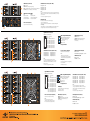
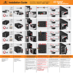
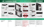
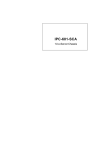
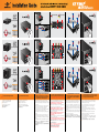
SATA/SAS Cable
Power Cable
Mounting Screws
Key x2
x4
Mounting Screws
Key x2
x8
Mounting Screws
Key x2
x12
1. Verify the package contents
Compruebe el contenido del paquete
Verificare i contenuti della confezione
Lieferumfang prüfen
Vérifiez le contenu de l'emballage
梱包内容を確認します
确认包装内容
Install storage unit into an open 5.25”
Connect power and SATA/SAS* data
2. Remove all carrier trays
drive bay and secure the unit using
3. the
correct mounting screws shown
cable on the back of the storage unit
4. *SATA
drive HAVE to be connected to SATA controller
Quite toda las bandejas portadoras
Rimuovere tutti i cassetti
Alle Trägereinsätze entfernen
Retirez tous les plateaux de support
キャリアトレーをすべて取り除きます
移除所有拖盘
Instale la unidad de almacenamiento en una bahía de
unidades de 5,25” y fije la unidad utilizando los tornillos de
instalación correctos mostrados a ambos lados de la unidad
almacenamiento
Installare l’unità d’archiviazione in un alloggio unità 5,25” e
fissarla su entrambi i lati utilizzando le viti appropriate
Installieren Speichereinheit in einem offenen 5,25
Speichergerät in einem freien 5,25-Zoll-Laufwerkseinschub
installieren und das Gerät mit Hilfe der richtigen
Montageschrauben an beiden Seiten des Speichergerätes
befestigen
Installez l'unité de stockage dans un logement de lecteur
5,25" ouvert et fixez l'appareil à l'aide des vis de montage
adéquates, comme indiqué sur les deux côtés de l'unité de
stockage
空いている5.25インチドライブベイにストレージユニッ
トを配置し、ユニットの両側に表示されている適切なマ
ウントねじを使用して固定します
将本装置安装至5.25”硬盘架上,并注意使用正确的螺丝
来固定此装置
Conecte el cable de datos SATA/SAS* y el de alimentación en
la parte posterior de la unidad de almacenamiento
on both sides of the storage unit
and SAS drives HAVE to be connected to SAS controller
* La unidad SATA tiene que conectarse a la controladora
SATA y las unidades SAS a la controladora SAS
Collegare il cavo d’alimentazione ed il cavo dati SATA/SAS*
sulla parte posteriore dell’unità d’archiviazione
* L’unità SATA DEVE essere collegata al controller SATA e le
unità SAS DEVONO essere collegate al controller SAS
Netz- und SATA/SAS*-Datenkabel an der Rückseite des
Speichergerätes anschließen
* SATA-Festplatten MÜSSEN mit dem SATA-Controller und
SAS-Festplatten MÜSSEN mit dem SAS-Controller
verbunden werden
Branchez l'alimentation et le câble de données SATA / SAS* à
l'arrière de l'unité de stockage
* Le lecteur SATA DOIT être connecté au contrôleur SATA et
les lecteurs SAS DOIVENT être connectés au contrôleur SAS
電源およびSATA/SAS*データケーブルをストレージユニ
ットの背面に接続します
* SATAドライブはSATAコントローラに接続し、SASドライブは
SASコントローラに接続する必要があります
连接背面的电源线与SATA/SAS*缆线
* SATA/ SAS需连接至各自相对应的插槽
5.
Install HDDs/SSDs on to the carrier
trays using the 4 correct mounting
screws shown on the underside of
the tray
Instale las unidades de disco duro y de estado sólido en las
bandejas portadoras utilizando 4 tornillos de instalación
correctos mostrados en la parte inferior de la bandeja
Installare le unità HDD/SSD nei cassetti utilizzando le 4 viti
appropriate come mostrato sulla parte inferiore del cassetto
HDDs/SSDs an den Trägereinsätzen installieren; dazu die 4
richtigen Montageschrauben an der Unterseite des Einsatzes
verwenden
Installez les disques durs / SSD sur les plateaux de support en
utilisant les vis de fixation de 4 adéquates, comme indiqué
sur la face inférieure du plateau
キャリアトレーの下部に示されているとおりに、
HDD/SSDを4サイズの適切なマウントねじで設置します
将HSS/SSD安装到托盘上,并于拖盘下方使用4个螺丝固定
Carefully slide the tray with the mounted
hard drive into the storage bay, close the
6. securing
arm and lock the tray
Deslice con cuidado la bandeja con la unidad de disco duro
montada en la bahía de almacenamiento, cierre el brazo de
seguridad y bloquee la bandeja
Fare scorrere delicatamente il cassetto con il disco rigido
installato nell’alloggio, chiudere il braccio di fissaggio e
bloccare il cassetto
Einsatz mit der montierten Festplatte vorsichtig in den
Speichereinschub schieben, Sicherungsarm schließen und
Einsatz verriegeln
Faites glisser délicatement le plateau avec le disque dur
monté dans le logement du lecteur, refermez le bras de
fixation et verrouillez le plateau
ハードドライブをマウントしたトレーをゆっくりとスト
レージベイにスライドして入れ、固定アームを閉じてト
レーをロックします
小心的将锁上硬碟的拖盘滑入插槽,关闭门板并上锁
B01
L01
L03
L02
L04
B03
B02
B04
LED Indicators (L01-L04)
SATA/SAS Port Connectors (D01 - D04)
BLUE - Power ON
PURPLE - Disk performing reading/writing
RED - On all 4 LEDs (L0l-L04), constant flashing indicate FAN Failure
NO LED - No power to the drive bay, no drive in the tray
Data port (D01) - B01
Data port (D02) - B02
Data port (D03) - B03
Data port (D04) - B04
Note:
1) You can mix SATA and SAS drives in the same storage unit, but SATA drives
HAVE to be connected to SATA controller and SAS drive HAVE to be connected
to SAS controller
2) SAS drive only support Primary Channel
LED Function Switch (SW1)
Left
Blue for Power LED
No Disk Activity LED
Red for Fan Failure LED
D03
P05
Right
Blue for Power LED
Purple for Disk Activity LED
Red for Fan Failure LED
FANS (F01, F02)
D01
F02
F01
D04
Both Fans pull air from the front of the Storage Bays.
It uses two 40x40x20mm Fans.
If any one of the Fans fails, the Four LED (L01- L04) will start blinking RED
Over Heating
If the Four LED (L01 – L04) start to blink RED very rapidly, the temperature in
the Storage Bay have exceeded the safe temperature of 60 degree C.
Power Connector (P05)
Single Power connection for all 4 Bays
D02
SW1
Signal Extension Connectors
(HDD activity, Fan, Temperature)
P01
B01
B02
L01
L02
L05
L06
B05
T +, TR - Temperature
F+, FR - Fan
Hdd+, l - HDD activity LED for B01
Hdd+, 2 - HDD activity LED for B02
Hdd+, 3 - HDD activity LED for B03
Hdd+, 4 - HDD activity LED for B04
Hdd+, 5 - HDD activity LED for B05
Hdd+, 6 - HDD activity LED for B06
Hdd+, 7 - HDD activity LED for B07
Hdd+, 8 - HDD activity LED for B08
P02
D05
D01
D06
D02
B06
F01
B03
B04
L03
L04
L07
L08
B07
B08
D07
D03
D08
D04
P01
B01
B02
B03
L01
L07
L02
L08
L03
L09
L04
L10
P02
B05
B06
L05
L06
L11
L12
SATA/SAS Port Connectors (D01 - D08)
Power Connector (P01,P02)
LED Temperature Status (T1)
Dual Power connection for all 8 Bays
Normal – No LED
Exceeded safe temp of 60 degrees C – Solid RED
Data port (D05) - B05
Data port (D06) - B06
Data port (D07) - B07
Data port (D08) - B08
(HDD activity, Fan, Temperature)
D01
D08
D02
B08
B09
D03
B10
D10
D04
D11
D05
B11
B12
D06
D12
Fan Speed Switch
Note:
-Both Power connectors must be
connected from the system power supply
-Power load balance by all attached drives
FANS (F01)
LED Fan Status (F1)
Normal – No LED
Fan Failure – Solid RED
Fan pulls air from the front of the Storage Bays.
Fan size: 70x70mm
FAN Failure see F1 status
Signal Extension Connectors
P03
D07
F01
LED Indicators (L01-L08)
GREEN - Power ON
ORANGE - Disk performing reading/writing
NO LED - No power to the drive bay, no
drive in the tray
Data port (D01) - B01
Data port (D02) - B02
Data port (D03) - B03
Data port (D04) - B04
Note:
1) You can mix SATA and SAS drives in the same
storage unit, but SATA drives HAVE to be connected to
SATA controller and SAS drive HAVE to be connected
to SAS controller
2) SAS drive only support Primary Channel
B07
D09
B04
SW1
HDD activity LED Switch(SW1)
ON – Show Disk Activity (Orange LED)
Off – Show only Green Power LED
(If Drive(s) is in the tray)
Low – 2400 rpm
High – 3000 rpm
T+, TR - Temperature
F+, FR - Fan
Hdd+, l - HDD activity LED for B01
Hdd+, 2 - HDD activity LED for B02
Hdd+, 3 - HDD activity LED for B03
Hdd+, 4 - HDD activity LED for B04
Hdd+, 5 - HDD activity LED for B05
Hdd+, 6 - HDD activity LED for B06
Hdd+, 7 - HDD activity LED for B07
Hdd+, 8 - HDD activity LED for B08
Hdd+, 9 - HDD activity LED for B09
Hdd+, 10 - HDD activity LED for B10
Hdd+, 11 - HDD activity LED for B11
Hdd+, 12 - HDD activity LED for B12
HDD activity LED Switch(SW1)
SATA/SAS Port Connectors (D01 - D12)
ON – Show Disk Activity (Orange LED)
Off – Show only Green Power LED
(If Drive(s) is in the tray)
Low – 2400 rpm
High – 3000 rpm
Data port (D01) - B01
Data port (D02) - B02
Data port (D03) - B03
Data port (D04) - B04
Data port (D05) - B05
Data port (D06) - B06
Fan Speed Switch
FANS (F01)
Fan pulls air from the front of the Storage Bays.
Fan size: 80 x 80 x15mm
FAN Failure see F1 status
Data port (D07) - B07
Data port (D08) - B08
Data port (D09) - B09
Data port (D10) - B10
Data port (D11) - B11
Data port (D12) - B12
Note:
1) You can mix SATA and SAS drives in the same
storage unit, but SATA drives HAVE to be connected to
SATA controller and SAS drive HAVE to be connected
to SAS controller
2) SAS drive only support Primary Channel
Power Connector (P01,P02,P03 )
LED Indicators (L01-L12)
LED Temperature Status (T1)
Three Power connection for all 12 Bays
GREEN - Power ON
ORANGE - Disk performing reading/writing
NO LED - No power to the drive bay, no
drive in the tray
Normal – No LED
Exceeded safe temp of 60 degree C – Solid RED
Note:
-Three Power connectors must be
connected from the system power supply
-Power load balance by all attached drives
LED Fan Status (F1)
Normal – No LED
Fan Failure – Solid RED
SW1
v 1.01
Model: MRK-M2504T/MRK-M2508T/MRK-M2512T
www.vantecusa.com