1
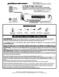
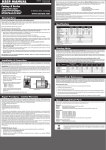
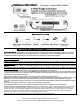
~ TOOLS REQUIRED ~ * IMPORTANT PRODUCT INFORMATION * *BEFORE YOU START: Check with your local building jurisdiction as to permit, license or code requirements for installing wire or outlets within a wall. Some municipalities require an electrical inspection for any modification of electrical work. HD-Products, recommends all modifications or alterations of existing or new electrical work to be inspected by a licensed electrical inspector. THIS PRODUCT IS NOT TO BE INSTALLED, DIRECT WIRED, CONNECTED OR BRANCHED TO THE BUILDING ELECTRICAL CIRCUIT/WIRING SYSTEM ! INSTALL THIS PRODUCT ONLY AS AN ELECTRICAL EXTENSION PLUG-IN DEVICE TO AN EXISTING, A/C GROUNDED OUTLET TO ENERGIZE A/C POWER USING A UL LISTED PLUG-IN CORD SET WHEN INSTALLED WITH SPECIFIED CODE COMPLIANT BUILDING ELECTRICAL WIRE. > Install this product to meet National Electrical Code and or State/Local Building Code as to requirements for installing electrical building wire and outlets as a single EXTENSION CIRCUIT, without modification or alteration to the building electrical circuit/wiring system. THIS PRODUCT MUST BE INSTALLED TO A UL CLASSIFIED SINGLE GANG ELECTRICAL JUNCTION BOX TO MEET CODE COMPLIANCY AND TO ASSURE SAFETY. > The supplied non-metallic junction boxes may not meet some local code requirements, as metal junction boxes may be required for certain installations where it may require Metal-Clad or Armored-Clad building wire. Please read and understand all instructions. Follow WARNING and CAUTION labels on the product. Use 12-2 or 14-2 Copper Utility [CU] wire only with this product. This product is rated to use with an existing A/C outlet 125v grounded circuit only. For shock protection, do not install this product to a non-grounded outlet/system. Do not install this product near water, example, near a sink, tub, shower, swimming pool or laundry area. Manufacturer is not liable for damages due to improper installation methods not followed herein or as required by national electrical or local building code. > Installation Code Compliancy is the responsibility of user and or installer and not of the Manufacturer or it’s agents. If you are not skilled with running wires through wall; it is strongly recommended that a qualified installation professional should install this product. This product does not have built-in electronic circuitry for surge protection or A/C filtering. It is recommended that this product be connected to a quality surge-protector/power conditioner for equipment protection. Limited 2-year Warranty from Manufactures Defects. HD-Products, Inc. the Manufacturer, it's agents, suppliers, and affiliates, shall not be liable for damages, not limited to; misuse, acts of nature, verbal and written expression and improper installation. Improper installation is determined such to include, not limited to, non-code compliant installation, product modifications, alterations, adjustments, and connections using non-code compliant methods and or materials. Your TSPBIW has a limited two year product warranty against manufacturer’s defects. If you have any questions or experience any problems with your product, please contact PowerBridge Customer Service. Maximum claim liability not to exceed the product purchase price or Manufacturers Suggested Retail Price. HD Products Inc. PowerBridge 3869 Norwood Drive Littleton, CO 80125 USA. Customer Service: 303.683.2434 x4101 [email protected]. www.PowerBridge1.com STEP 1 TV/PROJECTOR location ~ POWER OUTLET Wall Plate ~ (Female Receptacle) Determine where the TV wall-mount will be installed, on which side, (above or below the mount) will be best suited for the location of the TV power connection and not to interfere with the TV installation on the mount. ~ Measure height and width of TV to keep the wall plate hidden behind the TV. Wall plates can be installed up to 75-feet apart with additional in-wall power-wire. Source Equipment / Existing A/C Outlet location ~ POWER INLET Wall Plate ~ (Male Plug) Determine location on the wall near the source equipment or within 60 inches of an existing A/C outlet. LEVEL The POWER OUTLET and POWER INLET plates can be installed either vertically or horizontally ~ Determine location on wall/ceiling between framing studs, with a stud-finder. ~ Trace a cut-line with the supplied cardboard template. ~ Level for proper alignment. ~ Cut around outside of line, using a drywall saw or utility knife. ~ CAUTION: DO NOT CUT AREA BETWEEN LARGE AND SMALL OPENING STEP 2 ~Route In-Wall PowerWire within wall ~ ~ Route In-Wall PowerWire within wall/ceiling between the two larger cutouts. ~ Route Audio/Video Cables within wall/ceiling between the two smaller cutouts. ~ Using a screwdriver, bend one tab OUT on the backside of the WHITE box. ~ Insert PowerWire. Allow 4 inches to stick out from the edge of the box, strip off 3 inches of the outer sheath of the power-wire. ~ Insert the WHITE box into the wall opening. ~ Screw in the 2 silver screws to open the wall-wings to secure the boxes to the wallboard. ~ Use a level for proper alignment. L E V E L STEP 3 ~Follow the In-Wall PowerWire CONNECTION label on the backside of the wall plates.~ Trim ¾” length from both ends of the BLACK and WHITE covering of the ends of the wires. Bare wire is Ground to Green Screw A B POWER OUTLET ~ (Female Receptacle) (A) Using the tip of needle-nose pliers or the “bend hole” on a wire stripper, bend the wire-end into a “J” shaped hook. (B) Hook the wire-end on the right “clockwise” side of the screw as shown. Tighten the screws to each wire. ~ Check for proper wiring connections as labeled. C POWER INLET ~ (Male Plug) *DO NOT BEND OR “J” THE END OF THE WIRES. (C) Insert each of the three wires straight into the WIRE INSERT HOLES located on end of the INLET. Each hole aligns with a colored screw around the sides. Tighten the screws to each wire. ~ Check for proper wiring connections as labeled. Push excess electrical wire back through rear opening of the WHITE box. Secure both wall plates with color - matched screws. STEP 4 POWER INLET ~ Plug “female” end of the POWER CORD, onto the “male” plug of the POWER INLET. ~ Plug “male” plug of the POWER CORD into the existing A/C outlet or power surge protector. THE SYSTEM IS NOW POWERED NOTE: If the supplied POWER CORD is not long enough, DO NOT EXTEND THE SUPPLIED CORD with another extension cord. Must use 3 prong-grounded, UL LISTED extension cord. DO NOT EXCEED 15 FEET IN LENGTH. POWER OUTLET OPTIONAL: CHECK FOR PROPER WIRING CONNECTIONS WITH AN OUTLET-TESTER The HDTV is now ready to plug in, enjoy your wall-mounted system! ETL LISTED CONFORMS TO UL STD 514C CERTIFIED TO CAN/CSA STD C22.2 NO. 42.1 Model TSPBIW The manufacturer, intend to make this manual accurate and complete. However, no claim that the information contained herein covers all details, conditions, or variations. Nor does it provide for every possible contingency in connection with the installation or use of this product. The information contained in this document is subject to change without notice or obligation of any kind. Manufacturer makes no representation of specific warranty beyond the Limited Warranty, expressed or implied, regarding the information contained herein. ©2007-11 Ver.4.811