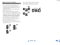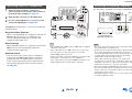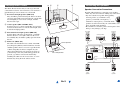
1
Contents
AV RECEIVER
HT-R391
Safety Information and Introduction ............2
Table of Contents ...........................................6
Connections .................................................12
Turning On & Basic Operations..................20
Instruction Manual
Advanced Operations ..................................37
Controlling Other Components...................48
Appendix .......................................................54
Speaker Package
En
Safety Information and Introduction
WARNING:
TO REDUCE THE RISK OF FIRE OR ELECTRIC SHOCK,
DO NOT EXPOSE THIS APPARATUS TO RAIN OR
MOISTURE.
CAUTION:
TO REDUCE THE RISK OF ELECTRIC SHOCK, DO NOT
REMOVE COVER (OR BACK). NO USER-SERVICEABLE
PARTS INSIDE. REFER SERVICING TO QUALIFIED
SERVICE PERSONNEL.
WARNING
AVIS
RISK OF ELECTRIC SHOCK
DO NOT OPEN
RISQUE DE CHOC ELECTRIQUE
NE PAS OUVRIR
The lightning flash with arrowhead symbol, within an
equilateral triangle, is intended to alert the user to the
presence of uninsulated “dangerous voltage” within
the product’s enclosure that may be of sufficient
magnitude to constitute a risk of electric shock to
persons.
The exclamation point within an equilateral triangle is
intended to alert the user to the presence of important
operating and maintenance (servicing) instructions in
the literature accompanying the appliance.
Important Safety Instructions
1.
2.
3.
4.
5.
6.
7.
Read these instructions.
Keep these instructions.
Heed all warnings.
Follow all instructions.
Do not use this apparatus near water.
Clean only with dry cloth.
Do not block any ventilation openings. Install in
accordance with the manufacturer’s instructions.
8. Do not install near any heat sources such as radiators,
heat registers, stoves, or other apparatus (including
amplifiers) that produce heat.
9. Do not defeat the safety purpose of the polarized or
grounding-type plug. A polarized plug has two blades
with one wider than the other. A grounding type plug
has two blades and a third grounding prong. The wide
blade or the third prong are provided for your safety. If
the provided plug does not fit into your outlet, consult
an electrician for replacement of the obsolete outlet.
10. Protect the power cord from being walked on or
pinched particularly at plugs, convenience receptacles,
and the point where they exit from the apparatus.
11. Only use attachments/accessories specified by the
manufacturer.
12. Use only with the cart, stand,
PORTABLE CART WARNING
tripod, bracket, or table
specified by the manufacturer,
or sold with the apparatus.
When a cart is used, use
caution when moving the
cart/apparatus combination to
S3125A
avoid injury from tip-over.
13. Unplug this apparatus during lightning storms or when
unused for long periods of time.
14. Refer all servicing to qualified service personnel.
Servicing is required when the apparatus has been
damaged in any way, such as power-supply cord or
plug is damaged, liquid has been spilled or objects
have fallen into the apparatus, the apparatus has been
exposed to rain or moisture, does not operate normally,
or has been dropped.
15. Damage Requiring Service
Unplug the apparatus from the wall outlet and refer
servicing to qualified service personnel under the
following conditions:
A. When the power-supply cord or plug is damaged,
B. If liquid has been spilled, or objects have fallen
into the apparatus,
C. If the apparatus has been exposed to rain or water,
En-2
D. If the apparatus does not operate normally by
following the operating instructions. Adjust only
those controls that are covered by the operating
instructions as an improper adjustment of other
controls may result in damage and will often
require extensive work by a qualified technician to
restore the apparatus to its normal operation,
E. If the apparatus has been dropped or damaged in
any way, and
F. When the apparatus exhibits a distinct change in
performance this indicates a need for service.
16. Object and Liquid Entry
Never push objects of any kind into the apparatus
through openings as they may touch dangerous voltage
points or short-out parts that could result in a fire or
electric shock.
The apparatus shall not be exposed to dripping or
splashing and no objects filled with liquids, such as
vases shall be placed on the apparatus.
Don’t put candles or other burning objects on top of
this unit.
17. Batteries
Always consider the environmental issues and follow
local regulations when disposing of batteries.
18. If you install the apparatus in a built-in installation,
such as a bookcase or rack, ensure that there is
adequate ventilation.
Leave 20 cm (8") of free space at the top and sides and
10 cm (4") at the rear. The rear edge of the shelf or
board above the apparatus shall be set 10 cm (4") away
from the rear panel or wall, creating a flue-like gap for
warm air to escape.
The temperature protection operates if the apparatus
attain an abnormal high temperature.
The apparatus cannot operate until it has cooled down.
Safety Information and Introduction
Precautions
1. Recording Copyright—Unless it’s for personal use
only, recording copyrighted material is illegal without
the permission of the copyright holder.
2. AC Fuse—The AC fuse inside the unit is not userserviceable. If you cannot turn on the unit, contact your
Onkyo dealer.
3. Care—Occasionally you should dust the unit all over
with a soft cloth. For stubborn stains, use a soft cloth
dampened with a weak solution of mild detergent and
water. Dry the unit immediately afterwards with a
clean cloth. Don’t use abrasive cloths, thinners,
alcohol, or other chemical solvents, because they may
damage the finish or remove the panel lettering.
4. Power
WARNING
BEFORE PLUGGING IN THE UNIT FOR THE
FIRST TIME, READ THE FOLLOWING SECTION
CAREFULLY.
AC outlet voltages vary from country to country. Make
sure that the voltage in your area meets the voltage
requirements printed on the unit’s rear panel (e.g., AC
230 V, 50 Hz or AC 120 V, 60 Hz).
The power cord plug is used to disconnect this unit
from the AC power source. Make sure that the plug is
readily operable (easily accessible) at all times.
5. Preventing Hearing Loss
Caution
Excessive sound pressure from earphones and
headphones can cause hearing loss.
6. Batteries and Heat Exposure
Warning
Batteries (battery pack or batteries installed) shall not
be exposed to excessive heat as sunshine, fire or the
like.
7. Never Touch this Unit with Wet Hands—Never
handle this unit or its power cord while your hands are
wet or damp. If water or any other liquid gets inside
this unit, have it checked by your Onkyo dealer.
8. Handling Notes
• If you need to transport this unit, use the original
packaging to pack it how it was when you originally
bought it.
• Do not leave rubber or plastic items on this unit for a
long time, because they may leave marks on the
case.
• This unit’s top and rear panels may get warm after
prolonged use. This is normal.
• If you do not use this unit for a long time, it may not
work properly the next time you turn it on, so be sure
to use it occasionally.
For models with [POWER] button, or with both
[POWER] and [ON/STANDBY] buttons:
Pressing the [POWER] button to select OFF mode
does not fully disconnect from the mains. If you do not
intend to use the unit for an extended period, remove
the power cord from the AC outlet.
For models with [ON/STANDBY] button only:
Pressing the [ON/STANDBY] button to select
Standby mode does not fully disconnect from the
mains. If you do not intend to use the unit for an
extended period, remove the power cord from the AC
outlet.
En-3
For U.S. models
FCC Information for User
CAUTION:
The user changes or modifications not expressly approved
by the party responsible for compliance could void the
user’s authority to operate the equipment.
NOTE:
This equipment has been tested and found to comply with
the limits for a Class B digital device, pursuant to Part 15
of the FCC Rules. These limits are designed to provide
reasonable protection against harmful interference in a
residential installation.
This equipment generates, uses and can radiate radio
frequency energy and, if not installed and used in
accordance with the instructions, may cause harmful
interference to radio communications. However, there is no
guarantee that interference will not occur in a particular
installation. If this equipment does cause harmful
interference to radio or television reception, which can be
determined by turning the equipment off and on, the user is
encouraged to try to correct the interference by one or more
of the following measures:
• Reorient or relocate the receiving antenna.
• Increase the separation between the equipment and
receiver.
• Connect the equipment into an outlet on a circuit different
from that to which the receiver is connected.
• Consult the dealer or an experienced radio/TV technician
for help.
Safety Information and Introduction
For Canadian Models
NOTE: THIS CLASS B DIGITAL APPARATUS
COMPLIES WITH CANADIAN ICES-003.
For models having a power cord with a polarized plug:
CAUTION: TO PREVENT ELECTRIC SHOCK,
MATCH WIDE BLADE OF PLUG TO WIDE SLOT,
FULLY INSERT.
Modèle pour les Canadien
REMARQUE: CET APPAREIL NUMÉRIQUE DE LA
CLASSE B EST CONFORME À LA NORME NMB-003
DU CANADA.
Sur les modèles dont la fiche est polarisée:
ATTENTION: POUR ÉVITER LES CHOCS
ÉLECTRIQUES, INTRODUIRE LA LAME LA PLUS
LARGE DE LA FICHE DANS LA BORNE
CORRESPONDANTE DE LA PRISE ET POUSSER
JUSQU’AU FOND.
En-4
Safety Information and Introduction
Supplied Accessories
■ Installing the batteries
Make sure you have the following accessories:
Indoor FM antenna (➔ page 19)
■ Aiming the remote controller
To use the remote controller, point it at the AV receiver’s
remote control sensor, as shown below.
Remote control sensor
AM loop antenna (➔ page 19)
AV receiver
Power cord (Brazilian models) (➔ page 19)
Remote controller (RC-799M) and two batteries (AA/R6)
Quick Start Guide
*
In catalogs and on packaging, the letter at the end of the product
name indicates the color. Specifications and operations are the
same regardless of color.
Approx. 16 ft. (5 m)
Batteries (AA/R6)
Note
• If the remote controller doesn’t work reliably, try replacing the
batteries.
• Don’t mix new and old batteries or different types of batteries.
• If you intend not to use the remote controller for a long time,
remove the batteries to prevent damage from leakage or
corrosion.
• Remove expired batteries as soon as possible to prevent damage
from leakage or corrosion.
Thank you for purchasing an Onkyo AV Receiver.
Please read this manual thoroughly before making
connections and plugging in the unit.
Following the instructions in this manual will
enable you to obtain optimum performance and
listening enjoyment from your new AV Receiver.
Please retain this manual for future reference.
En-5
Safety Information and Introduction
Table of Contents
Safety Information and Introduction
Important Safety Instructions ......................................2
Precautions ...................................................................3
Supplied Accessories...................................................5
Table of Contents..........................................................6
Features .........................................................................7
Front & Rear Panels......................................................8
Front Panel..................................................................8
Display ........................................................................9
Rear Panel ................................................................10
Remote Controller.......................................................11
Controlling the AV Receiver ......................................11
Using Basic Functions............................................... 28
Using the Listening Modes ....................................... 28
Using the Home Menu .............................................. 33
Selecting Speakers A and B ..................................... 33
Using the Sleep Timer .............................................. 34
Setting the Display Brightness.................................. 34
Displaying Source Information.................................. 34
Changing the Input Display....................................... 35
Using the Music Optimizer........................................ 35
Muting the AV Receiver ............................................ 35
Using Headphones ................................................... 36
Recording ................................................................. 36
Advanced Operations
Connecting the AV Receiver......................................12
Connecting Your Speakers .......................................12
About AV Connections ..............................................15
Connecting Components with HDMI .........................16
Connecting Your Components ..................................17
Connecting Onkyo u Components .........................18
Connecting a Recording Component ........................18
Connecting the Antennas..........................................19
Connecting the Power Cord ......................................19
On-screen Setup......................................................... 37
Common Procedures in Setup Menu........................ 37
Setup menu items..................................................... 38
HDMI Input................................................................ 39
Component (Component Video Input) ...................... 39
Digital Audio (Digital Audio Input) ............................. 40
Sp Config (Speaker Configuration)........................... 40
Sp Distance (Speaker Distance)............................... 41
Level Cal (Level Calibration)..................................... 41
Audio Adjust.............................................................. 42
Source Setup ............................................................ 43
Hardware .................................................................. 44
HDMI Setup .............................................................. 45
Using the Audio Settings .......................................... 46
Turning On & Basic Operations
Controlling Other Components
Turning On/Off the AV Receiver ................................20
Turning On ................................................................20
Turning Off ................................................................20
Playback ......................................................................21
Playing the Connected Component ..........................21
Controlling Contents of USB Devices .......................22
Understanding Icons on the Display .........................23
Playing an iPod/iPhone via USB ...............................23
Playing a USB Device ...............................................24
Listening to AM/FM Radio.........................................25
iPod/iPhone Playback via Onkyo Dock .................... 48
Using the Onkyo Dock .............................................. 48
Controlling Your iPod/iPhone.................................... 49
Controlling Other Onkyo Components..................... 50
Preprogrammed Remote Control Codes .................. 50
Entering Remote Control Codes............................... 50
Remote Control Codes for Onkyo Components
Connected via u .................................................. 50
Resetting the REMOTE MODE Buttons ................... 51
Resetting the Remote Controller .............................. 51
Controlling Other Components ................................. 52
Connections
En-6
Appendix
Troubleshooting ......................................................... 54
Connection Tips and Video Signal Path .................. 59
Using an RIHD-compatible TV, Player,
or Recorder .............................................................. 60
About HDMI................................................................. 62
USB Features.............................................................. 63
License and Trademark Information ........................ 64
Specifications ............................................................. 65
To reset the AV receiver to its factory defaults, turn it
on and, while holding down VCR/DVR, press
8ON/STANDBY (➔ page 54).
Safety Information and Introduction
Features
Amplifier
• 110 Watts/Channel @ 6 ohms (FTC)
• 100 Watts/Channel @ 6 ohms (IEC)
• 120 Watts/Channel @ 6 ohms (JEITA)
• Optimum Gain Volume Circuitry
• H.C.P.S. (High Current Power Supply) Massive High
Power Transformer
Processing
• HDMI (Audio Return Channel, 3D, DeepColor,
x.v.Color, Lip Sync, DTS-HD Master Audio, DTS-HD
High Resolution Audio, Dolby TrueHD, Dolby Digital
Plus, DSD and Multi-CH PCM)
• Non-Scaling Configuration
• A-Form Listening Mode Memory
• Direct Mode
• Music Optimizer for Compressed Digital Music files
• 192 kHz/24-bit D/A Converters
• Powerful and Highly Accurate 32-bit Processing DSP
• Jitter Cleaning Circuit Technology
Connections
• 4 HDMI Inputs and 1 Output
• Onkyo p for System Control
• 3 Digital Inputs (2 Optical/1 Coaxial)
• Component Video Switching (2 Inputs/1 Output)
• Front-Panel USB Input for Memory Devices and
iPod®/iPhone® models
Miscellaneous
• 40 FM/AM Presets
• EX.BASS for natural deeper bass
• Crossover Adjustment
(40/50/60/70/80/90/100/120/150/200 Hz)
• A/V Sync Control Function (up to 400 ms)
• Auto Standby Function
• On-Screen Display via HDMI
En-7
Safety Information and Introduction
Front & Rear Panels
Front Panel
(North American and Brazilian models)
a
op
cd
b
e
q
(Asian models)
f
g h ij k l m
r
u
n
s
t
For detailed information, see the pages in parentheses.
a 8ON/STANDBY button (20)
j DISPLAY button (34)
t USB port (17)
k SETUP button (37)
u RT/PTY/TP button (Asian models) (26)
b HDMI THRU indicator (45)
c SPEAKERS A and B buttons (33)
l TUNING q/w, PRESET e/r (25), cursor and
ENTER buttons
d Remote control sensor (5)
m RETURN button
e LISTENING MODE buttons (28)
n MASTER VOLUME control (21)
f Display (9)
o MUSIC OPTIMIZER button (35, 47)
g DIMMER button (North American and Brazilian
models) (34)
p PHONES jack (36)
q TONE and Level buttons (46)
h MEMORY button (26)
r Input selector buttons (21)
i TUNING MODE button (25)
s AUX INPUT AUDIO and VIDEO jacks (17)
En-8
Safety Information and Introduction
Display
a b
c
d
e
g
f
h
For detailed information, see the pages in parentheses.
a A and B speaker indicators (33)
b M.Opt indicator (35, 47)
c Listening mode and format indicators (28, 44)
d Tuning indicators
RDS indicator (excluding North American and
Brazilian models) (26)
AUTO indicator (25)
TUNED indicator (25)
FM STEREO indicator (25)
e SLEEP indicator (34)
f HDMI indicator (45, 59)
g MUTING indicator (35)
h Message area
En-9
Safety Information and Introduction
Rear Panel
(North American and Asian models)
a
b
(Brazilian models)
c
g
d
h
e
f
i
a DIGITAL IN COAXIAL and OPTICAL jacks
b COMPONENT VIDEO IN and OUT jacks
c HDMI IN and OUT jacks
h Composite video and analog audio jacks
(BD/DVD IN, VCR/DVR IN and OUT, CBL/SAT IN,
GAME IN, TV/CD IN)
d FM ANTENNA jack and AM ANTENNA terminal
i MONITOR OUT V jack
e SPEAKERS terminals
(FRONT A, CENTER, SURROUND,
SUBWOOFER, FRONT B)
j AC INLET (Brazilian models)
f Power cord (North American and Asian models)
See “Connecting the AV Receiver” for connection
(➔ pages 12 to 19).
g u REMOTE CONTROL jack
En-10
j
Safety Information and Introduction
Remote Controller
Controlling the AV Receiver
a
b
ic
j
c
d
ae
f
k
d
To control the AV receiver, press RECEIVER to select
Receiver mode.
You can also use the remote controller to control
Onkyo Blu-ray Disc/DVD player, CD player, and
other components.
See “Entering Remote Control Codes” for more
details (➔ page 50).
For detailed information, see the pages in parentheses.
a 8 button (20)
b REMOTE MODE/INPUT SELECTOR buttons (21)
c TONE and Level buttons (46)
d SP A/B button (33)
e q/w/e/r and ENTER buttons
f SETUP button (37)
g Listening Mode buttons (28)
l
m
h DIMMER button (34)
i DISPLAY button (34)
j MUTING button (35)
k VOL q/w button (21)
l RETURN button
m HOME button (33)
g
n SLEEP button (34)
e
bh
n
En-11
■ Controlling the tuner
To control the AV receiver’s tuner, press AM or FM (or
RECEIVER).
a q/w buttons (25)
b D.TUN button (25)
c DISPLAY button
d CH +/– button (26)
e Number buttons (25)
Connections
Connecting the AV
Receiver
Passive
Subwoofer
Surround
right
Surround
left
Connecting Your Speakers
Connecting the Speaker Cables
The following illustration shows how to connect the
speakers to each pair of terminals.
■ Using a Passive Subwoofer
Corner
position
1/3 of wall
position
To find the best position for your subwoofer, while playing
a movie or some music with good bass, experiment by
placing your subwoofer at various positions within the
room, and choose the one that provides the most satisfying
results.
Front B right
Front B left
Speakers B
■ Push-type speaker terminals
Strip 3/8" to 1/2" (10 to 12 mm) of insulation from the ends
of the speaker cables, and twist the bare wires tightly, as
shown (Supplied speaker cables are already stripped).
3/8" to 1/2" (10 to 12 mm)
En-12
Front A right
Center
Speakers A
Front A left
Connections
Speaker Configuration
Connecting the Speaker Cables
The following table indicates the channels you should use
depending on the number of speakers that you have.
No matter how many speakers you use, a passive
subwoofer is recommended for a really powerful and solid
bass.
To get the best from your surround sound system, you need
to set the speaker settings manually (➔ page 40).
The speaker terminals are color-coded for identification
purpose.
Surround left
Blue
Number of speakers
2
3
4
5
✔
✔
✔
Gray
Front speakers
✔
Surround right
Subwoofer
Purple
Center speaker
Surround speakers
✔
✔
✔
Speaker
Color
Front left
White
Front right
Red
Center
Green
✔
En-13
Connections
Speaker Connection Precautions
Read the following before connecting your speakers:
• You can connect speakers with an impedance of between
6 and 16 ohms. If you use speakers with a lower
impedance, and use the amplifier at high volume levels
for a long period of time, the built-in amp protection
circuit may be activated.
• Disconnect the power cord from the wall outlet before
making any connections.
• Read the instructions supplied with your speakers.
• Pay close attention to speaker wiring polarity. In other
words, connect positive (+) terminals only to positive (+)
terminals, and negative (–) terminals only to negative (–)
terminals. If you get them the wrong way around, the
sound will be out of phase and will sound unnatural.
• Unnecessarily long, or very thin speaker cables may
affect the sound quality and should be avoided.
• Be careful not to short the positive and negative wires.
Doing so may damage the AV receiver.
• Make sure the metal core of the wire does not have
contact with the AV receiver’s rear panel. Doing so may
damage the AV receiver.
• Don’t connect more than one cable to each speaker
terminal. Doing so may damage the AV receiver.
• Don’t connect one speaker to several terminals.
En-14
Connections
AV Cables and Jacks
About AV Connections
■ HDMI
HDMI connections can carry digital video and audio.
Connecting AV components
a
HDMI cable
■ Optical digital audio
Optical digital connections allow you to enjoy digital
sound such as PCM*1, Dolby Digital or DTS. The audio
quality is the same as coaxial.
: Video & Audio
TV, projector, etc.
■ Component video
Component video separates the luminance (Y) and color
difference signals (PB, PR), providing the best picture
quality (some TV manufacturers label their component
video sockets slightly differently).
AV receiver
■ Coaxial digital audio
Coaxial digital connections allow you to enjoy digital
sound such as PCM*1, Dolby Digital or DTS. The audio
quality is the same as optical.
Orange
Blu-ray Disc/
DVD player
Other cables
Game console
: Video
: Audio
TV, projector, etc.
AV receiver
Y
Green
PB
Blue
PR
Red
■ Analog audio (RCA)
Analog audio connections (RCA) carry analog audio.
White
■ Composite video
Composite video is commonly used on TVs, VCRs, and
other video equipment.
Red
*1
Yellow
Available sampling rate for PCM input signal (stereo/mono) is
32/44.1/48/88.2/96 kHz. In case of an HDMI connection,
176.4/192 kHz is also available.
Note
Blu-ray Disc/
DVD player
• The AV receiver does not support SCART plugs.
• The AV receiver’s optical digital jacks have shutter-type covers
that open when an optical plug is inserted and close when it’s
removed. Push plugs in all the way.
Game console
Caution
• Before making any AV connections, read the manuals
supplied with your AV components.
• Don’t connect the power cord until you’ve completed and
double-checked all AV connections.
• Push plugs in all the way to make
Right!
good connections (loose connections
can cause noise or malfunctions).
• To prevent interference, keep audio
and video cables away from power
Wrong!
cords and speaker cables.
• To prevent shutter damage, hold the optical plug straight
when inserting and removing.
En-15
Connections
Connecting Components with HDMI
VCR or DVD recorder/digital video recorder
Game console
TV, projector, etc.
Satellite/cable set-top box, etc.
*
*
Blu-ray Disc/DVD player
If your TV doesn’t support Audio Return Channel (ARC), you
need to connect an optical digital cable together with the HDMI
cable to the AV receiver.
When listening to an HDMI component through the AV
receiver, set the HDMI component so that its video can be seen
on the TV screen (on the TV, select the input of the HDMI
component connected to the AV receiver). If the TV power is off
or the TV is set to another input source, this may result in no
sound from the AV receiver or the sound may be cut off.
Connect your components to the appropriate jacks. The
default input assignments are shown below.
✔: Assignment can be changed (➔ page 39).
Jack
Components
✔
HDMI IN1
Blu-ray Disc/DVD player
HDMI IN2
VCR or DVD recorder/digital video recorder ✔
HDMI IN3
Satellite/cable set-top box, etc.
✔
HDMI IN4
Game console
✔
HDMI OUT
TV, projector, etc.
See also:
• “Connection Tips and Video Signal Path” (➔ page 59)
• “Using an RIHD-compatible TV, Player, or Recorder”
(➔ page 60)
• “About HDMI” (➔ page 62)
Tip
• To listen to the audio of a component connected via HDMI
through your TV’s speakers, enable “HDMI Through”
(➔ page 45) and set the AV receiver to standby mode.
Note
• In the case of Blu-ray Disc/DVD players, if no sound is output
despite following the above-mentioned procedure, set your Bluray Disc/DVD player’s HDMI audio settings to PCM.
En-16
■ Audio Return Channel (ARC) function
Audio Return Channel (ARC) function enables an HDMI
capable TV to send the audio stream to the HDMI OUT of
the AV receiver.
• This function can be used when:
– Your TV is ARC capable, and
– The TV/CD input selector is selected, and
– “HDMI Ctrl (RIHD)” is set to “On” (➔ page 45), and
– “Audio Return Ch (ARC)” is set to “Auto” (➔ page 46).
Connections
Connecting Your Components
A BC
The on-screen menus appear only on a TV that is
connected to the HDMI OUT. If your TV is connected
to other video outputs, use the AV receiver’s display
when changing settings.
Note
*1
*2
✔: Assignment can be changed (➔ pages 39, 40).
No. Jack/Port
A
Components
*3
AUX INPUT
VIDEO
Camcorder, etc.
AUDIO L/R
D
E
B
USB, AUX INPUT
VIDEO*1
iPod/iPhone (video
playback)
C
USB*2
iPod/iPhone, MP3 player,
USB flash drive
D
DIGITAL IN
F
E
F
Connect your components to the appropriate jacks. The
default input assignments are shown below.
See “Connection Tips and Video Signal Path” for more
information (➔ page 59).
OPTICAL 1 (GAME)
Game console
✔
OPTICAL 2 (TV/CD)
TV, CD player
✔
COAXIAL (BD/DVD)
Blu-ray Disc/DVD player
✔
IN 1 (BD/DVD)
Blu-ray Disc/DVD player,
RI dock
✔
IN 2 (CBL/SAT)
Satellite/cable set-top box,
RI dock, etc.
✔
COMPONENT VIDEO
OUT
TV, projector, etc.
MONITOR OUT
TV, projector, etc.
BD/DVD IN
Blu-ray Disc/DVD player
VCR/DVR IN
VCR, DVD recorder/
digital video recorder, RI
dock
CBL/SAT IN
Satellite/cable set-top box,
etc.
GAME IN
Game console, RI dock
TV/CD IN
TV, CD player, cassette
tape deck, MD, CD-R,
Turntable*3, RI dock
En-17
When USB input is selected, you can input video signals from
the AUX INPUT VIDEO jack. Video signals input from AUX
INPUT VIDEO will be output from the MONITOR OUT jack.
Do not connect the AV receiver’s USB port to a USB port on
your computer. Music on your computer cannot be played
through the AV receiver in this way.
Connect a turntable (MM) that has a phono preamp built-in. If
your turntable (MM) doesn’t have it, you’ll need a
commercially available phono preamp.
If your turntable has a moving coil (MC) type cartridge, you’ll
need a commercially available MC head amp or MC
transformer as well as a phono preamp. See your turntable’s
manual for details.
• With connection D, you can enjoy Dolby Digital and
DTS.
• With connection F, if your Blu-ray Disc/DVD player has
both the main stereo and multichannel outputs, be sure to
connect to the main stereo.
■ How to record a video source
With the connections described above, you cannot record
the videos through the AV receiver. See “Recording” about
connections for video recording (➔ page 36).
Connections
Connecting a Recording Component
Connecting Onkyo u Components
1
Make sure that each Onkyo component is
connected with an analog audio cable (connection
F in the hookup examples) (➔ page 17).
2
3
Make the u connection (see the illustration).
See “Recording” for details on recording (➔ page 36).
If you’re using an RI Dock or cassette tape deck,
change the Input Display (➔ page 35).
With u (Remote Interactive), you can use the following
special functions:
e.g., cassette tape deck
■ System On/Auto Power On
When you start playback on a component connected via
u while the AV receiver is on standby, the AV
receiver will automatically turn on and select that
component as the input source.
■ Direct Change
When playback is started on a component connected via
u, the AV receiver automatically selects that
component as the input source.
■ Remote Control
You can use the AV receiver’s remote controller to
control your other u-capable Onkyo components,
pointing the remote controller at the AV receiver’s
remote control sensor instead of the component. You
must enter the appropriate remote control code first
(➔ page 50).
R
L
ANALOG
AUDIO OUT
L
R
AUDIO
IN
R
L
ANALOG
AUDIO OUT
RI Dock
Note
VIDEO
IN
VCR, DVD recorder,
cassette tape deck,
CDR, MD recorder, etc.
Note
• Use only u cables for u connections. u cables are supplied
with Onkyo components.
• Some components have two u jacks. You can connect either
one to the AV receiver. The other jack is for connecting
additional u-capable components.
• Connect only Onkyo components to u jacks. Connecting other
manufacturer’s components may cause a malfunction.
• Some components may not support all u functions. Refer to the
manuals supplied with your other Onkyo components.
En-18
• The AV receiver must be turned on for recording. Recording is
not possible while it’s in standby mode.
• If you want to record directly from your TV or playback VCR to
the recording VCR without going through the AV receiver,
connect the TV/VCR’s audio and video outputs directly to the
recording VCR’s audio and video inputs. See the manuals
supplied with your TV and VCR for details.
• Video signals connected to composite video inputs can be
recorded only via composite video outputs. For example, if your
TV/VCR is connected to a composite video input, the recording
VCR must be connected to a composite video output.
• The surround sound and DSP listening modes cannot be recorded.
• Copy-protected Blu-ray Discs and DVDs cannot be recorded.
• Sources connected to a digital input cannot be recorded. Only
analog inputs can be recorded.
• DTS signals will be recorded as noise, so don’t attempt analog
recording of DTS CDs or LDs.
Connections
Connecting the Antennas
Connecting the Power Cord
This section explains how to connect the supplied indoor FM antenna and AM loop antenna.
The AV receiver won’t pick up any radio signals without any antenna connected, so you must connect the antenna to use
the tuner.
North American and
Brazilian models
1
(Brazilian models)
Connect the supplied power cord to the AV
receiver’s AC INLET.
Asian models
To AC wall outlet
Push.
Insert wire.
Release.
Insert the plug fully
into the jack.
Insert the plug fully
into the jack.
2
Assembling the AM loop antenna
Caution
Note
• Be careful not to injure yourself when
using thumbtacks.
Thumbtacks, etc.
AM loop antenna (supplied)
Plug the power cord into an AC wall outlet.
Indoor FM antenna (supplied)
Note
• Once your AV receiver is ready for use, you’ll need to tune into a radio station and position the antenna to achieve the best possible
reception.
• Keep the AM loop antenna as far away as possible from your AV receiver, TV, speaker cables, and power cords.
Tip
• If you cannot achieve good reception with the supplied indoor FM antenna, try a commercially available outdoor FM antenna instead.
• If you cannot achieve good reception with the supplied indoor AM loop antenna, try using it with a commercially available outdoor AM
antenna.
En-19
• Before connecting the power cord, connect all of your
speakers and AV components.
• Turning on the AV receiver may cause a momentary power surge
that might interfere with other electrical equipment on the same
circuit. If this is a problem, plug the AV receiver into a different
branch circuit.
• Do not use a power cord other than the one supplied with the AV
receiver. The supplied power cord is designed exclusively for use
with the AV receiver and should not be used with any other
equipment.
• Never disconnect the power cord from the AV receiver while the
other end is still plugged into a wall outlet. Doing so may cause
an electric shock. Always disconnect the power cord from the
wall outlet first, and then the AV receiver.
Turning On & Basic Operations
Turning On/Off the AV
Receiver
8ON/STANDBY
Turning On
1
Turning Off
Press 8ON/STANDBY on the front panel.
or
Press RECEIVER followed by 8 on the remote
controller.
The AV receiver comes on, and its display lights.
1
Press 8ON/STANDBY on the front panel.
or
Press RECEIVER followed by 8 on the remote
controller.
The AV receiver will enter standby mode. To prevent
any loud surprises when you turn on the AV receiver,
always turn down the volume before you turn it off.
Tip
• For details on power management settings, see “Auto Standby”
(➔ page 44).
8
RECEIVER
En-20
Turning On & Basic Operations
Playback
The on-screen menus appear only on a TV that is
connected to the HDMI OUT. If your TV is connected
to other video outputs, use the AV receiver’s display
when changing settings.
Playing the Connected Component
■ Operating on the AV receiver
Input selector buttons
■ Operating with the remote controller
LISTENING MODE
MASTER VOLUME
INPUT SELECTOR
RECEIVER
VOL q/w
This section describes the procedure for using the
remote controller unless otherwise specified.
Listening mode buttons
1
Press RECEIVER followed by an INPUT
SELECTOR button.
2
Start playback on the source component.
See also:
• “Playing an iPod/iPhone via USB” (➔ page 23)
• “Playing a USB Device” (➔ page 24)
• “Listening to AM/FM Radio” (➔ page 25)
• “iPod/iPhone Playback via Onkyo Dock”
(➔ page 48)
• “Controlling Other Onkyo Components”
(➔ page 50)
3
4
To adjust the volume, use VOL q/w.
Select a listening mode and enjoy!
See also:
• “Using the Listening Modes” (➔ page 28)
En-21
1
Use the input selector buttons to select the input
source.
2
3
Start playback on the source component.
4
Select a listening mode and enjoy!
To adjust the volume, use the MASTER VOLUME
control.
Turning On & Basic Operations
Controlling Contents of USB Devices
h
a TOP MENU
This button displays the top menu for each media or service.
o RANDOM
This button performs random playback.
b q/w and ENTER
These buttons navigate through the menus.
p REPEAT
Press this button repeatedly to cycle through the repeat
modes.
e/r
This button cycles through pages.
PLAYLIST e/r
In Standard Mode (iPod/iPhone), this button selects
playlists.
Press USB
first.
i
c 1
This button starts playback.
a
d 7
This button selects the beginning of the current song.
Pressing this button twice selects the previous song.
b
e 5
This button fast-reverses the current song.
c
j
d
e
f
k
l
m
g
n
o
p
f 3
This button pauses playback.
g SEARCH
You can toggle between the playback screen and the list
screen during playback.
h DISPLAY
This button switches between song information.
i CH +/–
In Standard Mode (iPod/iPhone), this button selects albums.
j RETURN
This button returns to the previous menu.
k 6
This button selects the next song.
l 4
This button fast-forwards the current song.
m 2
This button stops playback.
n MODE
You can switch between Extended Mode and Standard Mode
during iPod/iPhone playback.
En-22
Tip
• See “Controlling Other Onkyo Components” about the operation
of other components (➔ page 50).
Note
• The buttons you can use will differ depending on the devices and
media used for playback.
Turning On & Basic Operations
Understanding Icons on the Display
This section describes icons that appear on the AV
receiver’s display during media playback.
Icon
Playing an iPod/iPhone via USB
The on-screen menus appear only on a TV that is
connected to the HDMI OUT.
Description
Folder
Track
Playback
Pause
Fast Forward
Fast Reverse
This section explains how to play music files on the
iPod/iPhone.
Compatible iPod/iPhone models
Made for:
iPod touch (1st, 2nd, 3rd and 4th generation), iPod classic,
iPod nano (2nd, 3rd, 4th, 5th and 6th generation),
iPhone 4S, iPhone 4, iPhone 3GS, iPhone 3G, iPhone
1
2
Artist
Album
Repeat One Track
Repeat Folder (USB Device)
Repeat
Shuffle
Shuffle Album (iPod/iPhone)
3
Press USB to select the “USB” input.
Connect the USB cable that comes with the
iPod/iPhone to the USB port on the front of the AV
receiver.
While reading the contents of your iPod/iPhone, the
message “Connecting...” appears on the AV
receiver’s display.
A list of your iPod/iPhone model’s contents appears
(Extended Mode).
Use q/w to select a folder, and then press ENTER to
open it.
Tip
• If you want to operate using the iPod/iPhone or the remote
controller, press MODE to switch to Standard mode.
• When you disconnect the iPod/iPhone, the AV receiver
remembers the current mode. This means that if you
disconnect when in Extended Mode, the AV receiver will
start in Extended Mode the next time you connect the
iPod/iPhone.
• You can also use the q/w, ENTER and TUNING MODE
buttons on the front panel. TUNING MODE allows you to
switch modes.
• When connecting your iPod/iPhone with a USB cable, we
recommend you use an official USB cable from Apple Inc.
En-23
4
Use q/w to select a music file, and press ENTER or
1 to start playback.
Note
• While the message “Connecting...” appears on the AV receiver’s
display, do not disconnect the USB cable supplied with your
iPod/iPhone or the USB device from the USB port.
• If you connect an iPod or iPhone to the USB port, no sound will
be output from the headphones jack.
Extended Mode Control
The content information is displayed (lists are displayed),
and you can control the content while looking at the screen.
Top screen list:
Playlists, Artists, Albums, Genres, Songs, Composers,
Shuffle Songs, Now Playing.
Standard Mode Control
The content information is not displayed, but can be
operated using the iPod/iPhone or the remote controller.
Turning On & Basic Operations
Playing a USB Device
The on-screen menus appear only on a TV that is
connected to the HDMI OUT.
This section explains how to play music files from a USB
device (e.g., USB flash drives and MP3 players).
See also:
• “USB Features” (➔ page 63).
1
2
Press USB to select the “USB” input.
Plug your USB device into the AV receiver’s USB
port.
While reading the contents of your USB device, the
message “Connecting...” appears on the AV
receiver’s display.
3
Press ENTER.
A list of the device’s contents appears. To open a
folder, use q/w to select it, and then press ENTER.
4
Use q/w to select a music file, and press ENTER or
1 to start playback.
Note
• While the message “Connecting...” appears on the AV receiver’s
display, do not disconnect the USB cable supplied with your
iPod/iPhone or the USB device from the USB port.
En-24
Turning On & Basic Operations
Listening to AM/FM Radio
This section describes the procedure using the buttons
on the front panel unless otherwise specified.
Using the Tuner
With the built-in tuner you can enjoy AM and FM radio
stations. You can store your favorite stations as presets for
quick selection.
You can also change the frequency steps (➔ page 44).
1
■ Auto tuning mode
1
Press TUNING MODE so that the AUTO indicator
lights on the AV receiver’s display.
2
Press TUNING q/w.
Searching stops when a station is found.
When tuned into a station, the TUNED indicator
lights. When tuned into a stereo FM station, the FM
STEREO indicator lights as shown.
FM STEREO
Press AM or FM to select either “AM” or “FM”.
In this example, FM has been selected.
Band
■ Manual tuning mode
In manual tuning mode, FM stations will be in mono.
Tuning into Radio Stations
Frequency
1
Press TUNING MODE so that the AUTO indicator
goes off on the AV receiver’s display.
2
Press and hold TUNING q/w.
The frequency stops changing when you release the
button.
Press the buttons repeatedly to change the frequency
one step at a time.
■ Tuning into stations by frequency
You can tune into AM and FM stations directly by entering
the appropriate frequency.
1
AUTO
TUNED
(Actual display depends on the country.)
On the remote controller, press AM or FM to select
“AM” or “FM”, followed by D.TUN.
Tip
• Tuning into weak FM stereo stations
If the signal from a stereo FM station is weak, it may be
impossible to get good reception. In this case, switch to
manual tuning mode and listen to the station in mono.
En-25
(Actual display depends on the country.)
2
Within 8 seconds, use the number buttons to enter
the frequency of the radio station.
For example, to tune to 87.5 (FM), press 8, 7, 5.
If you have entered the wrong number, you can retry
after 8 seconds.
Turning On & Basic Operations
Presetting AM/FM Stations
■ Selecting Presets
You can store a combination of up to 40 of your favorite
AM/FM radio stations as presets.
1
1
Tune into the AM/FM station that you want to store
as a preset.
See the previous section.
2
Press MEMORY.
The preset number flashes.
(Actual display depends on the country.)
3
While the preset number is flashing (about 8
seconds), use PRESET e/r to select a preset from
1 through 40.
4
Press MEMORY again to store the station or
channel.
The station or channel is stored and the preset number
stops flashing.
Repeat this procedure for all of your favorite AM/FM
radio stations.
Using RDS (excluding North American and
Brazilian models)
To select a preset, use PRESET e/r on the AV
receiver, or the remote controller’s CH +/–.
Tip
• You can also use the remote controller’s number buttons to
select a preset directly.
■ Deleting Presets
1
Select the preset that you want to delete.
See the previous section.
2
While holding down MEMORY, press TUNING
MODE.
The preset is deleted and its number disappears from
the AV receiver’s display.
RDS works only in areas where RDS broadcasts are
available.
When tuned into an RDS station, the RDS indicator lights.
When the station is broadcasting text information, the text
can be displayed.
■ What is RDS?
RDS stands for Radio Data System and is a method of
transmitting data in FM radio signals. It was developed by
the European Broadcasting Union (EBU) and is available
in most European countries. Many FM stations use it these
days. In addition to displaying text information, RDS can
also help you find radio stations by type (e.g., news, sport,
rock, etc.).
The AV receiver supports four types of RDS information:
PS (Program Service)
When tuned to an RDS station that’s broadcasting PS
information, the station’s name will be displayed. Pressing
DISPLAY will display the frequency for 3 seconds.
RT (Radio Text)
When tuned to an RDS station that’s broadcasting text
information, the text will be shown on the AV receiver’s
display as described in the next section.
PTY (Program Type)
This allows you to search for RDS radio stations by type
(➔ page 27).
TP (Traffic Program)
This allows you to search for RDS radio stations that
broadcast traffic information (➔ page 27).
To be continued
En-26
Turning On & Basic Operations
Note
• In some cases, the text characters displayed on the AV receiver
may not be identical to those broadcast by the radio station. Also,
unexpected characters may be displayed when unsupported
characters are received. This is not a malfunction.
• If the signal from an RDS station is weak, RDS data may be
displayed intermittently or not at all.
■ Listening to Traffic News (TP)
RDS program types (PTY)
You can search for stations that broadcast traffic news.
Type
1
■ Displaying Radio Text (RT)
1
Press RT/PTY/TP once.
The RT information scrolls across the AV receiver’s
display.
Note
• The message “Waiting” may appear while the AV receiver
waits for the RT information.
• If the message “No Text Data” appears, no RT information
is available.
2
Display
None
None
Press RT/PTY/TP three times.
If the current radio station is broadcasting TP (Traffic
Program), “[TP]” will appear on the AV receiver’s
display. If “TP” without square brackets appears, this
means that the station is not broadcasting TP.
News reports
News
Current affairs
Affairs
Information
Info
To locate a station that is broadcasting TP, press
ENTER.
The AV receiver searches until it finds a station that’s
broadcasting TP.
If no stations are found, the message “Not Found”
appears.
Drama
Drama
Culture
Culture
Science and technology
Science
Varied
Varied
Sport
Sport
Education
Educate
Pop music
Pop M
Rock music
Rock M
Middle of the road music
Easy M
Light classics
Light M
Serious classics
Classics
■ Finding Stations by Type (PTY)
Other music
Other M
Weather
Weather
You can search for radio stations by type.
Finance
Finance
1
2
3
4
Children’s programmes
Children
Press RT/PTY/TP twice.
The current program type appears on the AV
receiver’s display.
Social affairs
Social
Religion
Religion
Phone in
Phone In
Use PRESET e/r to select the type of program
you want.
See the table shown later in this chapter.
Travel
Travel
To start the search, press ENTER.
The AV receiver searches until it finds a station of the
type you specified, at which point it stops briefly
before continuing with the search.
Country music
Country
National music
Nation M
When a station you want to listen to is found, press
ENTER.
If no stations are found, the message “Not Found”
appears.
Documentary
Document
Alarm test
TEST
Alarm
Alarm!
En-27
Leisure
Leisure
Jazz music
Jazz
Oldies music
Oldies
Folk music
Folk M
Turning On & Basic Operations
Using Basic Functions
MOVIE/TV button
This button selects the listening modes intended for use
with movies and TV.
MUSIC button
This button selects the listening modes intended for use
with music.
GAME button
This button selects the listening modes intended for use
with video games.
STEREO button
This button selects the Stereo listening mode and All
Channel Stereo listening mode.
Using the Listening Modes
Selecting Listening Modes
See “About Listening Modes” for detailed information
about the listening modes (➔ page 29).
■ Listening Mode Buttons
Press RECEIVER first.
MOVIE/TV, MUSIC, GAME
MUSIC
MOVIE/TV
GAME
STEREO
En-28
• The Dolby Digital and DTS listening modes can only be
selected if your Blu-ray Disc/DVD player is connected to
the AV receiver with a digital audio connection (coaxial,
optical, or HDMI).
• The listening modes you can select depends on the format
of the input signal. To check the format, see “Displaying
Source Information” (➔ page 34).
• While a pair of headphones is connected, you can select the
following listening modes: Direct, Stereo, and Mono.
• While Speakers A and B are on, you can select only the
Direct, Stereo, Mono, or T-D (Theater-Dimensional)
listening mode.
Turning On & Basic Operations
About Listening Modes
The AV receiver’s listening modes can transform your
listening room into a movie theater or concert hall, with
high fidelity and stunning surround sound.
■ Explanatory Notes
a
b
Input Source
The following audio formats are supported by the listening
mode.
A
This is mono (monophonic) sound.
S
This is stereo (stereophonic) sound. Two
independent audio signal channels are reproduced
through two speakers.
D
This is 5.1-channel surround sound. This surround
system has five main channels of sound and a sixth
subwoofer channel (called the point-one channel).
F*1 This is 7.1-channel surround sound. This is a further
sound enhancement to 5.1-channel sound with two
additional speakers that provide greater sound
envelopment and more accurate positioning of
sounds.
*1
Speaker Layout
The illustration shows which speakers are activated in each
channel. See “Sp Config (Speaker Configuration)” for the
speaker setup (➔ page 40).
Z
X
The AV receiver outputs this source in 5.1-channel surround
sound.
c
C
d
a Front speakers
b Center speaker
c Surround speakers
d Subwoofer
En-29
Turning On & Basic Operations
■ Onkyo-Original DSP Listening Modes
Listening Mode
Description
Orchestra*1
Suitable for classical or operatic music, this
mode emphasizes the surround channels in
order to widen the stereo image, and
simulates the natural reverberation of a large
hall.
Or ches t r a
Unplugged*1
Un p l u g g e d
Studio-Mix*1
S t u d i o –M i x
TV Logic*1
TV
Log i c
Game-RPG*1
G ame – RPG
Game-Action*1
G ame – A c t i o n
Game-Rock*1
G ame – R o c k
Game-Sports*1
G ame – S p o r t s
All Ch Stereo
A l l
Ch
S t e r eo
Full Mono
Fu l l
Mo n o
Input
Source
Speaker
Layout
A
S
D
F
C
Listening Mode
Description
Input
Source
Speaker
Layout
T-D (TheaterDimensional)*1
With this mode you can enjoy a virtual
surround sound even with only two or three
speakers. This works by controlling how
sounds reach the listener’s left and right ears.
Good results may not be possible if there’s
too much reverb, so we recommend that you
use this mode in an environment with little
or no natural reverb.
A
S
D
F
ZXC
T–D
Suitable for acoustic instruments, vocals,
and jazz, this mode emphasizes the front
stereo image, giving the impression of being
right in front of the stage.
Suitable for rock or pop music, listening to
music in this mode creates a lively sound
field with a powerful acoustic image, like
being at a club or rock concert.
This mode adds realistic acoustics to TV
shows produced in a TV studio, surround
effects to the entire sound, and clarity to
voices.
In this mode, the sound has a dramatic feel
with a similar atmosphere to Orchestra
mode.
In this mode, sound localization is distinct
with emphasis on bass.
In this mode, sound pressure is emphasized
to heighten live feel.
In this mode, reverberation is increased and
sound localization decreased slightly.
Ideal for background music, this mode fills
the entire listening area with stereo sound
from the front and surround speakers.
XC
In this mode, all speakers output the same
sound in mono, so the sound you hear is the
same regardless of where you are within the
listening room.
En-30
Turning On & Basic Operations
■ Listening Modes
Listening Mode
Description
Direct
In this mode, audio from the input source is
output without surround-sound processing.
The speaker configuration (presence of
speakers) and speaker distance settings are
enabled, but much of the processing set via
Home menu is disabled. A/V Sync does not
have effect on the analog audio. See “Onscreen Setup” for more details
(➔ page 37).
D i r ec t
Stereo
S t e r eo
Mono
Mo n o
Multichannel
Mu l t i c h
Input
Source
Speaker
Layout
A
S
D
F
ZXC
Description
DSD*2
In this mode, audio from the input source is D
output without surround-sound processing.
The speaker configuration (presence of
speakers), crossover frequency, speaker
distance, A/V Sync and much of the
processing set via Home menu are enabled.
D
See “On-screen Setup” for more details
(➔ page 37).
F
DSD
Dolby Digital
Do l b y
D
Dolby Digital Plus*3
Do l b y
D
+
Input
Source
Speaker
Layout
XC
XC
Dolby TrueHD
Do l b y
Sound is output from the front left and right
speakers and subwoofer.
T r u e HD
DTS
D
XC
D
F
XC
D
XC
D
XC
DTS
Use this mode when watching an old movie
with a mono soundtrack, or use it with the
foreign language soundtracks recorded in the
left and right channels of some movies. It
can also be used with DVDs or other sources
containing multiplexed audio, such as
karaoke DVDs.
This mode is for use with PCM multichannel D
sources.
F
Listening Mode
DTS-HD High
Resolution Audio
D T S – HD
HR
DTS-HD Master
Audio
XC
D T S – HD MS T R
DTS Express
DTS
Exp r ess
DTS 96/24
DTS
En-31
96 / 24
This mode is for use with DTS 96/24
sources. This is high-resolution DTS with a
96 kHz sampling rate and 24-bit resolution,
providing superior fidelity. Use it with
DVDs that bear the DTS 96/24 logo.
Turning On & Basic Operations
Listening Mode
Dolby Pro Logic II
PL
Mo v i e
PL
Mu s i c
PL
Game
Neo:6
Description
Input
Source
Speaker
Layout
Dolby Pro Logic II expands any 2-channel
source for 5.1-channel playback. It provides
a very natural and seamless surround-sound
experience that fully envelops the listener.
As well as music and movies, video games
can also benefit from the dramatic spatial
effects and vivid imaging.
• Dolby PLII Movie
S
Use this mode with DVDs and videos that
bear the Dolby Surround logo or TV shows
that feature Dolby Surround. You can also
use this mode with stereo movies or TV
shows and the AV receiver will create a 5.1
surround mix from the 2-channel stereo.
• Dolby PLII Music
Use this mode to add 5.1 surround to stereo
sources such as music CDs and DVDs.
• Dolby PLII Game
Use this mode when playing game discs.
Note
*1
These listening modes cannot be selected during USB or iPod playback.
The AV receiver can input the DSD signal from HDMI IN. Setting the output setting on the player
side to PCM might obtain a better sound according to the player. In that case, set the output setting
on the player side to PCM.
*3 For the Blu-ray Discs, Dolby Digital is used.
• The listening modes cannot be selected with some source formats.
*2
XC
This mode expands any 2-channel source for
up to 5.1-channel playback. It uses seven
full-bandwidth channels of matrix decoding
for matrix-encoded material, providing a
very natural and seamless surround sound
experience that fully envelops the listener.
Ne o : 6
C i n ema
Ne o : 6
Mu s i c
• Neo:6 Cinema
S
Use this mode with any stereo movie (e.g.,
TV, DVD, VHS).
• Neo:6 Music
Use this mode with any stereo music source
(e.g., CD, radio, cassette, TV, VHS, DVD).
XC
En-32
Turning On & Basic Operations
The Home menu provides quick access to frequently used
settings. You can change settings and view the current
information.
■ Listening Mode*2
` You can select the listening modes that are
grouped in the following categories:
“MOVIE/TV”, “MUSIC” and “GAME”.
Use q/w to select the category and e/r to
select the listening mode. Press ENTER to
switch to the selected listening mode.
The on-screen menus appear only on a TV that is
connected to the HDMI OUT. If your TV is connected
to other video outputs, use the AV receiver’s display
when changing settings.
Selecting Speakers A and B
You can use two sets of front speakers with the AV
receiver: Speakers A for up to 5.1-channel playback in
your main listening room and Speakers B for 2-channel
stereo playback in another room.
1
Speakers A → Speakers A&B → Speakers B
Off ←
Speaker indicators and output channels are shown
below.
Note
• The on-screen menus are displayed when:
– There is no video input, or
– The video input is 480p, 576p, 720p, 1080i, or 1080p.
Note
*1
*2
1
Press RECEIVER followed by HOME.
The Home menu will be superimposed on the TV
screen.
2
Use q/w and ENTER to make the desired selection.
Depending on the input source and listening mode, not all
channels shown here output the sound.
• This setting is not available in either of the following cases:
–The “Audio TV Out” setting is set to “On” (➔ page 45).
–“HDMI Ctrl (RIHD)” is set to “On” (➔ page 45) and
you’re listening through your TV speakers.
Press RECEIVER once followed by SP A/B
repeatedly to cycle through the selection:
→
■ Info*1
` You can view the information of the following
items: “Input” and “Output”.
Using the Home Menu
Speaker indicators Output channel
Speakers A: 5.1 channels
A
A
B
Speakers A: 2.1 channels*3
Speakers B: 2 channels
B
Speakers B: 2 channels
No sound
■ Input
`You can select the input source.
Use q/w to select the desired input source.
Pressing ENTER switches to the selected input
source.
*3
While Speakers B is on, channels are reduced to 2.1 in the
main room.
Tip
• Alternatively, you can use the AV receiver’s SPEAKERS
A and B.
■ Audio
`You can change the following settings: “Bass”,
“Treble”, “Subwoofer Level”, “Center Level”,
“EX.BASS”, “Late Night”, “Music Optimizer”,
and “Cinema Filter”.
See also:
• “Using the Audio Settings” (➔ page 46)
En-33
Turning On & Basic Operations
Using the Sleep Timer
With the sleep timer, you can set the AV receiver to turn
off automatically after a specified period.
1
Press RECEIVER once followed by SLEEP
repeatedly to select the required sleep time.
The sleep time can be set from 90 to 10 minutes in 10
minute steps.
The SLEEP indicator lights on the AV receiver’s
display when the sleep timer has been set. The
specified sleep time appears for about 5 seconds, then
the previous display reappears.
Setting the Display Brightness
You can adjust the brightness of the AV receiver’s display.
1
Press RECEIVER once followed by DIMMER
repeatedly to switch between: normal, dim, or
dimmer brightness.
Displaying Source Information
You can display various information about the current
input source as follows.
1
Tip
Press RECEIVER once followed by DISPLAY
repeatedly to cycle through the available
information.
Tip
• (North American and Brazilian models) Alternatively,
you can use the AV receiver’s DIMMER.
• Alternatively, you can use the AV receiver’s DISPLAY.
The following information can typically be displayed.
Input source &
volume*1
Tip
• If you need to cancel the sleep timer, press SLEEP
repeatedly until the SLEEP indicator goes off.
• To check the time remaining until the AV receiver sleeps,
press SLEEP. Note that if you press again on SLEEP as
the time being displayed is equal to 10 minutes or less, the
sleep timer will go off.
Listening mode
Signal format*2
or sampling
frequency
*1
*2
En-34
When AM or FM radio is used, the band, frequency, and preset
number are displayed.
If the input signal is digital, the signal format is displayed.
Information is displayed for about three seconds, then the
previously displayed information reappears.
Turning On & Basic Operations
Changing the Input Display
When you connect an u-capable Onkyo component, you
must configure the input display so that u can work
properly.
This setting can be done only from the front panel.
Press and hold down the same button (about
3 seconds) to change the input display.
Repeat this step to select the desired input display.
■ TV/CD:
TV/CD → DOCK
TAPE
■ GAME:
GAME ↔ DOCK
→
2
Press TV/CD, GAME or VCR/DVR.
“TV/CD”, “GAME” or “VCR/DVR” appears on the
AV receiver’s display.
The Music Optimizer function enhances the sound quality
of compressed music files.
1
Press MUSIC OPTIMIZER on the front panel.
The M.Opt indicator lights on the AV receiver’s
display.
Tip
• Alternatively, you can use the remote controller’s HOME.
• See “Music Optimizer” for more details (➔ page 47).
→
1
Using the Music Optimizer
■ VCR/DVR: VCR/DVR ↔ DOCK
Note
• “DOCK” can be selected for the “TV/CD”, “GAME” or
“VCR/DVR” input selector, but not at the same time.
• Enter the appropriate remote control code before using the
remote controller for the first time (➔ page 50).
En-35
Muting the AV Receiver
You can temporarily mute the output of the AV receiver.
1
Press RECEIVER followed by MUTING.
The output is muted and the MUTING indicator
flashes on the AV receiver’s display.
Tip
• To unmute, press MUTING again or adjust the volume.
• Muting is automatically cancelled when the AV receiver is
set to standby.
Turning On & Basic Operations
Using Headphones
1
Connect a pair of stereo headphones with a
standard plug (1/4 inch or 6.3 mm) to the PHONES
jack.
Note
• Always turn down the volume before connecting your
headphones.
• While the headphones plug is inserted in the PHONES
jack, the speakers are turned off.
• When you connect a pair of headphones, the listening mode
is set to Stereo, unless it’s already set to Stereo, Mono, or
Direct.
• If you connect an iPod or iPhone to the USB port on the AV
receiver, no sound will be output from the headphones jack.
Recording
This section explains how to record the selected input
source to a component with recording capability.
AV Recording
Audio sources can be recorded to a recorder (e.g., cassette
tape deck, CDR, MD recorder). Video sources can be
recorded to a video recorder (e.g., VCR, DVD recorder).
1
Use the input selector buttons to select the source
that you want to record.
You can watch the source while recording. The AV
receiver’s MASTER VOLUME control has no effect
on recording.
2
3
On your recorder, start recording.
On the source component, start playback.
If you select another input source during recording,
that input source will be recorded.
En-36
Advanced Operations
On-screen Setup
Common Procedures in Setup Menu
The setup menus provides a convenient way to change the
AV receiver’s various settings. Settings are organized into
10 categories.
a
Remote indicator
The on-screen menus appear only on a TV that is
connected to the HDMI OUT. If your TV is connected
to other video outputs, use the AV receiver’s display
when changing settings.
b
c
Menu
Sp Config
■ Subwoofer
` Yes
` No
RECEIVER
a Menu selection
b Setting target
c Setting options (default setting underlined)
ENTER
q/w/e/r
This section describes the procedure for using the
remote controller unless otherwise specified.
RETURN
SETUP
Note
• The on-screen menus are displayed when:
– There is no video input, or
– The video input is 480p, 576p, 720p, 1080i, or 1080p.
Explanatory Notes
1
2
Press RECEIVER followed by SETUP.
3
Use q/w to select a setting target, and use e/r to
change the setting.
Press SETUP to close the menu.
Press RETURN to return to the previous menu.
Use q/w to select a menu item, and then press
ENTER.
Note
• This procedure can also be performed on the AV receiver by
using SETUP, the cursor buttons, and ENTER.
En-37
Menu
1.
2.
3.
4.
5.
6.
7.
8.
9.
10.
HDMI Input
Component
Digital Audio
Sp Config
Sp Distance
Level Cal
Audio Adjust
Source Setup
Hardware
HDMI Setup
Menu
BD/DVD
VCR/DVR
CBL/SAT
GAME
AUX
TUNER
TV/CD
Setting target
Advanced Operations
Setup menu items
Menu item
Setting target
Level Cal
(➔ page 41)
Left
Center
Menu item
Setting target
HDMI Input
(➔ page 39)
BD/DVD
Right
VCR/DVR
Surround Right
CBL/SAT
Surround Left
Subwoofer
GAME
AUX
TV/CD
Component
(➔ page 39)
Audio Adjust
(➔ page 42)
Panorama
VCR/DVR
Dimension
CBL/SAT
Center Width
GAME
Center Image
TV/CD
Listening Angle
BD/DVD
Source Setup
(➔ page 43)
GAME
AUX
Double Bass
Sp Distance
(➔ page 41)
Unit
Remote ID
Auto Standby
Front
Crossover
Volume OSD
AM/FM Freq Step
AM Freq Step
Subwoofer
Surround
Name
Fixed Mode
Hardware
(➔ page 44)
TV/CD
Center
A/V Sync
Audio Selector
VCR/DVR
CBL/SAT
Sp Config
(➔ page 40)
Input Ch (Mono)
BD/DVD
AUX
Digital Audio
(➔ page 40)
Input Ch (Mux)
HDMI Setup
(➔ page 45)
HDMI Ctrl (RIHD)
HDMI Through
Audio TV Out
Audio Return Ch
LipSync
Left
Center
Right
Surround Right
Surround Left
Subwoofer
En-38
Advanced Operations
HDMI Input
1
2
Menu
Component (Component Video Input)
Note
3
4
5
6
HDMI Input
If you connect a video component to an HDMI input, you
must assign that input to an input selector. For example, if
you connect your Blu-ray Disc/DVD player to HDMI IN 2,
you must assign “HDMI2” to the “BD/DVD” input
selector.
Here are the default assignments.
Input selector
Default assignment
BD/DVD
HDMI1
VCR/DVR
HDMI2
CBL/SAT
HDMI3
GAME
HDMI4
AUX
TV/CD
• If no video component is connected to HDMI output (even if the
HDMI input is assigned), the AV receiver selects the video
source based on the setting of “Component (Component Video
Input)”.
• When an HDMI IN is assigned to an input selector as explained
here, the same HDMI IN will be set as a priority in the “Digital
Audio (Digital Audio Input)” (➔ page 40). In this case, if you
want to use the coaxial or optical audio input, make the
appropriate selection in the “Audio Selector” setting
(➔ page 43).
• Do not assign an HDMI IN to the TV/CD selector while “HDMI
Ctrl (RIHD)” is set to “On” (➔ page 45), otherwise
appropriate CEC (Consumer Electronics Control) operation will
not be guaranteed.
• If you assign “- - - - -” to an input selector that is currently
selected in “HDMI Through” (➔ page 45), the “HDMI
Through” setting will be automatically switched to “Off”.
• The “TUNER” selector cannot be assigned and is fixed at the
“- - - - -” option.
1
2
Menu
3
4
6
Component
If you connect a video component to a component video
input, you must assign that input to an input selector. For
example, if you connect your Blu-ray Disc/DVD player to
COMPONENT VIDEO IN 2, you must assign “IN2” to
the “BD/DVD” input selector.
Here are the default assignments.
Input selector
Default assignment
BD/DVD
IN1
VCR/DVR
-----
CBL/SAT
IN2
GAME
-----
-----
AUX
-----
-----
TV/CD
-----
■ BD/DVD, VCR/DVR, CBL/SAT, GAME, AUX,
TV/CD
` HDMI1, HDMI2, HDMI3, HDMI4:
Select the input to which the component has been
connected.
` - - - - -:
Select if you’re not using the HDMI OUT.
Each HDMI input cannot be assigned to two input
selectors or more. When HDMI1 - HDMI4 have already
been assigned, you must first set any unused input
selectors to “- - - - -” or you will be unable to assign
HDMI1 - HDMI4 to input selector.
5
■ BD/DVD, VCR/DVR, CBL/SAT, GAME, AUX,
TV/CD
`IN1, IN2:
Select the input to which the component has been
connected.
`- - - - -:
Select if you’re not using the COMPONENT
VIDEO OUT.
Note
• The “TUNER” selector cannot be assigned and is fixed at the
“- - - - -” option.
En-39
Advanced Operations
Digital Audio (Digital Audio Input)
1
2
3
4
5
Sp Config (Speaker Configuration)
6
1
2
3
4
5
6
■ Front
`Small:
`Large:
Select based on the cone diameter.
Note
Menu
Digital Audio
If you connect a component to a digital audio input, you
must assign that input to an input selector. For example, if
you connect your CD player to the OPTICAL IN 1, you
must assign “OPTICAL1” to the “TV/CD” input selector.
Here are the default assignments.
Input selector
Menu
Sp Config
This section explains how to specify which speakers are
connected and their sizes.
Cone diameter
Default assignment
BD/DVD
COAXIAL
VCR/DVR
-----
CBL/SAT
-----
GAME
OPTICAL1
AUX
-----
TV/CD
OPTICAL2
■ BD/DVD, VCR/DVR, CBL/SAT, GAME, AUX,
TV/CD
` COAXIAL, OPTICAL1, OPTICAL2:
Select the input to which the component has been
connected.
` - - - - -:
Select if the component is connected to an analog
audio input.
Note
• When an HDMI IN is assigned to an input selector in
“HDMI Input” (➔ page 39), the same HDMI IN will be set as
a priority in this assignment. In this case, if you want to use the
coaxial or optical audio input, make the appropriate selection in
the “Audio Selector” (➔ page 43).
• Available sampling rates for PCM signals (stereo/mono) from a
digital input (optical and coaxial) are 32/44.1/48/88.2/96 kHz/16,
20, 24 bit.
• The “TUNER” selector cannot be assigned and is fixed at the
“- - - - -” option.
• If the “Subwoofer” setting is set to “No”, this setting is fixed to
“Large”.
■ Center*1, Surround*1
`Small:
`Large:
Select based on the cone diameter.
`None
Note
For speakers with a cone diameter larger than 6-1/2 inches
(16 cm), specify Large (full band). For those with a
smaller diameter, specify Small (default crossover
120 Hz).
The crossover frequency can be changed in the “Crossover
(Crossover Frequency)”.
Note
• These settings are not available in either of the following cases:
– A pair of headphones is connected.
– The “Audio TV Out” setting is set to “On” (➔ page 45).
– “HDMI Ctrl (RIHD)” is set to “On” (➔ page 45) and you’re
listening through your TV speakers.
– Speakers B is on.
– Speakers A is off.
*1
If the “Front” setting is set to “Small”, the “Large” option
cannot be selected.
■ Crossover (Crossover Frequency)
This setting is advantageous for the speakers that you
specified as “Small” in the “Sp Config (Speaker
Configuration)”. To get the best bass performance from
your speaker system, you need to set the crossover
frequency according to the size and frequency response
of your speakers.
`40Hz, 50Hz, 60Hz, 70Hz, 80Hz, 90Hz, 100Hz,
120Hz, 150Hz, 200Hz
Use the diameter of the smallest speaker in your system
when choosing the crossover frequency.
Speaker cone diameter
■ Subwoofer
` Yes
` No
Crossover frequency
Over 8 in. (20 cm)
40/50/60 Hz*2
6-1/2 to 8 in. (16 to 20 cm)
70/80/90 Hz*2
5-1/4 to 6-1/2 in. (13 to 16 cm)
100 Hz
3-1/2 to 5-1/4 in. (9 to 13 cm)
120 Hz
Under 3-1/2 in. (9 cm)
150/200 Hz*2
*2
Choose the setting suitable for the speaker.
To be continued
En-40
Advanced Operations
Note
• For a more accurate setting, look up the frequency response in the
manuals supplied with your speakers and set accordingly.
• Choose a higher crossover frequency if you want more sound
from your subwoofer.
■ Double Bass
` On
` Off
Turn this setting on to boost bass output by feeding bass
sounds from the front left, right, and center channels to the
subwoofer.
Note
• When the “Subwoofer” setting is set to “No” or the “Front”
setting to “Small”, this setting is fixed to “Off” (➔ page 40).
• This setting is set to “On” automatically when the “Subwoofer”
and “Front” settings are set for the first time to “Yes” and
“Large” respectively.
Sp Distance (Speaker Distance)
1
Menu
2
3
4
5
Level Cal (Level Calibration)
6
Sp Distance
Here you can specify the distance from each speaker to the
listening position so that the sound from each speaker
arrives at the listener’s ears as the sound designer intended.
Note
1
2
Menu
3
4
5
6
Level Cal
Here you can adjust the level of each speaker with the
built-in test tone so that the volume of each speaker is the
same at the listening position.
Note
• These settings are not available in either of the following cases:
– A pair of headphones is connected.
– The “Audio TV Out” setting is set to “On” (➔ page 45).
– “HDMI Ctrl (RIHD)” is set to “On” (➔ page 45) and you’re
listening through your TV speakers.
– Speakers B is on.
– Speakers A is off.
■ Unit
` feet:
Distances can be set in feet. Range: 1ft to 30ft in
1 foot steps.
` meters:
Distances can be set in meters. Range: 0.3m to 9.0m
in 0.3 meter steps.
(The default setting varies from country to country.)
■ Left, Center, Right, Surround Right, Surround
Left, Subwoofer
` Specify the distance from the each speaker to your
listening position.
• These settings cannot be calibrated in either of the following
cases:
– A pair of headphones is connected.
– The “Audio TV Out” setting is set to “On” (➔ page 45).
– “HDMI Ctrl (RIHD)” is set to “On” (➔ page 45) and you’re
listening through your TV speakers.
– Speakers B is on.
– Speakers A is off.
– The AV receiver is muted.
■ Left, Center*1, Right, Surround Right, Surround
Left
`–12 dB to 0 dB to +12 dB in 1 dB step.
■ Subwoofer*1
`–15 dB to 0 dB to +12 dB in 1 dB step.
Note
• Speakers that you set to “No” or “None” in the “Sp Config
(Speaker Configuration)” (➔ page 40) cannot be selected.
*1 For the center speaker and subwoofer, the level settings made
by using the Home menu are saved in this menu (➔ page 33).
Tip
Note
• Speakers that you set to “No” or “None” in the “Sp Config
(Speaker Configuration)” (➔ page 40) cannot be selected.
En-41
• If you’re using a handheld sound level meter, adjust the level of
each speaker so that it reads 75 dB SPL at the listening position,
measured with C-weighting and slow reading.
Advanced Operations
Audio Adjust
1
2
3
Menu
4
5
6
Audio Adjust
With the Audio Adjust functions and settings, you can
adjust the sound and listening modes as you like.
Multiplex/Mono
■ Multiplex
Input Ch (Mux)
` Main
` Sub
` Main/Sub
This setting determines which channel of a stereo
multiplex source is output. Use it to select audio channels
or languages with multiplex sources, multilingual TV
broadcasts, and so on.
■ Mono
Input Ch (Mono)
` Left + Right
` Left
` Right
This setting specifies the channel to be used for playing
any 2-channel digital source such as Dolby Digital, or 2channel analog/PCM source in the Mono listening mode.
Dolby
DTS
■ PL II Music (2ch Input)
These settings apply to only 2-channel stereo sources.
■ Neo:6 Music
Panorama
` On
` Off
With this setting, you can broaden the width of the front
stereo image when using the Dolby Pro Logic II Music
listening mode.
Dimension
` –3 to 0 to +3
With this setting, you can move the sound field forward or
backward when using the Dolby Pro Logic II Music
listening mode. Higher settings move the sound field
backward. Lower settings move it forward.
If the stereo image feels too wide, or there’s too much
surround sound, move the sound field forward to improve
the balance. Conversely, if the stereo image feels like it’s
in mono, or there’s not enough surround sound, move it
backward.
Center Width
` 0 to 3 to 7
With this setting, you can adjust the width of the sound
from the center speaker when using the Dolby Pro Logic II
Music listening mode. Normally, if you’re using a center
speaker, the center channel sound is output from only the
center speaker. (If you’re not using a center speaker, the
center channel sound will be distributed to the front left
and right speakers to create a phantom center). This setting
controls the front left, right, and center mix, allowing you
to adjust the weight of the center channel sound.
En-42
Center Image
`0 to 2 to 5
With this setting, you can specify by how much the front
left and right channel output is attenuated in order to create
the center channel.
Changing the value from “0” to “5” will spread the sound
of the center channel to left and right (outwards).
Theater-Dimensional
■ Listening Angle
`Wide:
Select if the listening angle is 40 degrees.
`Narrow:
Select if the listening angle is 20 degrees.
With this setting, you can optimize the TheaterDimensional listening mode by specifying the angle of the
front left and right speakers relative to the listening
position. Ideally, the front left and right speakers should be
equidistant from the listening position and at an angle close
to one of the two available settings.
Front left speaker
Front right speaker
20°/40°
Advanced Operations
Source Setup
1
2
3
4
5
6
Items can be set individually for each input selector.
Preparation
Press the input selector buttons to select an input source.
Menu
Source Setup
A/V Sync
■ A/V Sync
` 0 ms to 400 ms in 10 msec steps
When using progressive scanning on your Blu-ray
Disc/DVD player, you may find that the picture and sound
are out of sync. With this setting, you can correct this by
delaying the audio signals.
To view the TV picture while setting the delay, press
ENTER.
To return to the previous screen, press RETURN.
Preset Name For Input Selector
Audio Selector
■ Name
` - - -, Blu-ray, DVD, HD DVD, VCR, DVR, Tivo,
CableSTB, SAT STB, PS3, Wii, Xbox, PC, TV, CD,
TAPE, iPod:
To reset to the default, select “- - -”.
You can enter a preset name for each individual input
selector for easy identification. When entered, the preset
name will be displayed.
■ Audio Selector
`ARC:
The audio signal from your TV tuner can be sent to
the HDMI OUT of the AV receiver.*1
With this selection, the TV’s audio can be
automatically selected as a priority among other
assignments.
`HDMI:
This can be selected when HDMI IN has been
assigned as an input source. If both HDMI (HDMI
IN) and digital audio inputs (COAXIAL IN or
OPTICAL IN) have been assigned, HDMI input is
automatically selected as a priority.
`COAXIAL:
This can be selected when COAXIAL IN has been
assigned as an input source. If both coaxial and
HDMI inputs have been assigned, coaxial input is
automatically selected as a priority.
`OPTICAL:
This can be selected when OPTICAL IN has been
assigned as an input source. If both optical and HDMI
inputs have been assigned, optical input is
automatically selected as a priority.
`Analog:
The AV receiver always outputs analog signals.
You can set priorities of audio output when there are both
digital and analog inputs.
Note
• You can’t assign the same preset name to multiple input selectors.
• This setting cannot be used for the AM, FM or USB input
selector.
The range of values you can adjust will depend on whether
your TV supports HDMI Lip Sync and if the “LipSync”
setting is set to “On” or not (➔ page 46).
Note
• A/V Sync is disabled when the Direct listening mode is used with
an analog input source.
Note
• This setting can be made only for the input source that is assigned
as HDMI IN, COAXIAL IN, or OPTICAL IN.
*1 You can select “ARC” if you select the TV/CD input selector.
But you cannot if you’ve selected “Off” in the “Audio Return
Ch” setting (➔ page 46).
En-43
Advanced Operations
Setting the Incoming Digital Signal (Fixed
Mode)
■ Fixed Mode
` Off:
The format is detected automatically. If no digital
input signal is present, the corresponding analog
input is used instead.
` PCM:
Only 2-channel PCM format input signals will be
heard. If the input signal is not PCM, the PCM
indicator will flash and noise may also be produced.
` DTS:
Only DTS (but not DTS-HD) format input signals
will be heard. If the input signal is not DTS, the dts
indicator will flash and there will be no sound.
When “HDMI”, “COAXIAL” or “OPTICAL” is selected
in the “Audio Selector” setting, you can then specify the
signal type in “Fixed Mode”.
Normally, the AV receiver detects the signal format
automatically. However, if you experience either of the
following issues when playing PCM or DTS material, you
can manually set the signal format to PCM or DTS.
• If the beginnings of tracks from a PCM source are cut off,
try setting the format to PCM.
• If noise is produced when fast forwarding or reversing a
DTS CD, try setting the format to DTS.
Note
• The setting will be reset to “Off” when you change the setting in
the “Audio Selector” (➔ page 43).
Tuner
.
Hardware
1
2
Menu
3
4
5
6
Hardware
OSD
■ AM/FM Freq Step (North American and Brazilian
models)
`10kHz/200kHz:
`9kHz/50kHz:
Select the frequency step according to your area.
■ Volume OSD
` On
` Off
Turn this setting on to display the volume level on the TV
screen while it is adjusted.
■ AM Freq Step (Asian models)
`10kHz:
`9kHz:
Select the frequency step according to your area.
For AM/FM tuning to work properly, you must specify the
AM/FM frequency step used in your area.
Remote ID
• When this setting is changed, all radio presets will be deleted.
Note
■ Remote ID
` 1, 2, or 3
When several Onkyo components are used in the same
room, their remote ID codes may overlap. To differentiate
the AV receiver from the other components, you can
change its remote ID from “1”, to “2” or “3”.
Note
• If you do change the AV receiver’s remote ID, be sure to change
the remote controller to the same ID (see below), otherwise, you
won’t be able to control it with the remote controller.
Changing the remote controller’s ID
1
2
While holding down RECEIVER, press and hold
down SETUP until the remote indicator lights
(about 3 seconds).
Use the number buttons to enter ID 1, 2, or 3.
The remote indicator flashes twice.
En-44
Auto Standby
■ Auto Standby
`Off
`On
When “Auto Standby” is set to “On”, the AV receiver
will automatically enter standby mode if there is no
operation for 30 minutes with no audio and no video signal
input.
“Auto Standby” will appear on the AV receiver’s display
and OSD 30 seconds before the Auto Standby comes on.
Default setting: On (Asian models), Off (North
American and Brazilian models)
Note
• Set to “On”, the Auto Standby function may activate itself during
playback with some sources.
Advanced Operations
• When the source equipment is connected with the u
connection, it may malfunction if “HDMI Ctrl (RIHD)” is set to
“On”.
HDMI Setup
1
Menu
2
3
4
5
6
HDMI Setup
■ HDMI Ctrl (RIHD)
` Off
` On
Turn this setting on to allow p-compatible
components connected via HDMI to be controlled by the
AV receiver (➔ page 60).
Note
• When the setting is set to “On” and the menu is closed, the names
of connected p-compatible components and “RIHD On”
are displayed on the AV receiver.
“Search…” → “(name)” → “RIHD On”
When the AV receiver cannot receive the name of the component,
it is displayed as “Player*” or “Recorder*”, etc (“*” shows up
and indicates the number of components, when two or more are
received).
• When an p-compatible component is connected to the
AV receiver via an HDMI cable, the name of the connected
component is displayed on the AV receiver display. For example,
while you are watching TV broadcasting, if you operate a Blu-ray
Disc/DVD player (being powered on) with the remote control of
the AV receiver, the name of the Blu-ray Disc/DVD player will
be displayed on the AV receiver.
• Set it to “Off” when a connected piece of equipment is not
compatible or it is unclear whether the equipment is compatible
or not.
• If operation is not normal when set to “On”, change the setting to
“Off”.
• Refer to the connected component’s instruction manual for
details.
• When the “HDMI Ctrl (RIHD)” setting is set to “On”, the power
consumption in standby mode slightly increases. (Depending on
the TV status, the AV receiver will enter standby mode as usual.)
■ HDMI Through
` Off
` BD/DVD, VCR/DVR, CBL/SAT, GAME, AUX,
TV/CD:
Selects the input source for which the HDMI
Through function is enabled.
` Last:
The HDMI Through function is activated on the input
source selected at the time of setting the AV receiver
to standby mode.
When enabling the HDMI Through function, regardless of
whether the AV receiver is on or in standby, both audio
and video streams from an HDMI input will be output to
the TV or other components via HDMI connection. In
standby mode, the HDMI THRU and HDMI indicators
will light (HDMI will be dimly-lit).
This setting is fixed to “Auto” automatically when the
above “HDMI Ctrl (RIHD)” setting is set to “On”,
resulting in automatic input source selection.
Note
• Only the input source assigned to the HDMI IN via
“HDMI Input” is enabled (➔ page 39).
• The power consumption in standby mode will increase during the
HDMI Through function; however in the following cases, the
power consumption can be saved:
– The TV is in standby mode.
– You are watching a TV program.
• Refer to the connected component’s instruction manual for
details.
• Depending on the connected component, the correct input source
may not be selected with the setting fixed to “Auto”.
• This setting is set to “Off” automatically when the “HDMI Ctrl
(RIHD)” setting is set to “Off”.
En-45
■ Audio TV Out
`Off
`On
This preference determines whether the incoming audio
signal is output from the HDMI output. You may want to
turn this preference on if your TV is connected to the
HDMI output and you want to listen to the audio from a
connected component through your TV’s speakers.
Normally, this should be set to “Off”.
Note
• If “On” is selected and the audio can be output from the TV, the
AV receiver will output no sound through its speakers. In this
case, “TV Speaker” appears on the AV receiver’s display by
pressing DISPLAY.
• When “HDMI Ctrl (RIHD)” is set to “On”, this setting is fixed
to “Auto”.
• With some TVs and input signals, no sound may be output even
when this setting is set to “On”.
• When “Audio TV Out” or “HDMI Ctrl (RIHD)” is set to “On”
and you’re listening through your TV’s speakers (➔ page 16),
turning up the AV receiver’s volume control will make the sound
be output from the AV receiver’s front left and right speakers. To
stop the AV receiver’s speakers producing sound, change the
settings, change your TV’s settings, or turn down the AV
receiver’s volume.
• Listening mode cannot be changed when this setting is set to
“On” and the input source is not HDMI.
Advanced Operations
■ Audio Return Ch (ARC)
` Off
` Auto:
The audio signal from your TV tuner can be sent to
the HDMI OUT of the AV receiver.
The audio return channel (ARC) function allows an ARC
capable TV to send the audio stream to the HDMI OUT of
the AV receiver. To use this function, you must select the
TV/CD input selector and your TV must be ARC capable.
Using the Audio Settings
You can change various audio settings from the Home
menu (➔ page 33).
1
2
Press RECEIVER followed by HOME.
Use q/w and ENTER to select “Audio”, and then
use q/w/e/r to make the desired selection.
Note
• This setting is fixed to “- - - -” when the “HDMI Ctrl (RIHD)”
setting is set to “Off”.
• This setting is set to “Auto” automatically when the “HDMI Ctrl
(RIHD)” setting is set to “On” for the first time.
• If you set “Audio Return Ch” to “Auto”, the “Audio Selector”
settings of the TV/CD input selector will be automatically
switched to “ARC” (➔ page 43).
■ LipSync
` Off
` On
This function allows the AV receiver to automatically
correct any delay between the video and the audio, based
on the data from the connected monitor.
Note
• This function works only if your HDMI-compatible TV supports
HDMI Lip Sync.
After changing the settings of the “HDMI Ctrl
(RIHD)”, “HDMI Through” or “Audio Return Ch”
turn off the power on all connected pieces of equipment
and then turn them on again. Refer to the user’s manuals
for all connected pieces of equipment.
Speaker Levels
■ Subwoofer Level
`–15 dB to 0 dB to +12 dB in 1 dB steps
Operating on the remote controller directly
1
Press RECEIVER once followed by TONE
repeatedly to select “Subwoofer”.
2
Use – and + to adjust.
Note
• These settings are not available in either of the following cases:
– The “Audio TV Out” setting is set to “On” (➔ page 45).
– “HDMI Ctrl (RIHD)” is set to “On” (➔ page 45) and you’re
listening through your TV speakers.
Tone Control
■ Bass
` –10 dB to 0 dB to +10 dB in 2 dB steps
You can boost or cut low-frequency sounds output
from the front speakers.
■ Treble
` –10 dB to 0 dB to +10 dB in 2 dB steps
You can boost or cut high-frequency sounds output
from the front speakers.
You can adjust the bass and treble for Speakers A and B
front speakers, except when the Direct listening mode is
selected.
Operating on the remote controller directly
1
Press RECEIVER once followed by TONE
repeatedly to select either “Bass” or “Treble”.
2
Use – and + to adjust.
Tip
• Alternatively, you can use the AV receiver’s TONE and –/+.
En-46
Tip
• Alternatively, you can use the AV receiver’s TONE and –/+.
■ Center Level
`–12 dB to 0 dB to +12 dB in 1 dB steps
You can adjust the volume of each speaker while listening
to an input source.
These temporary adjustments are cancelled when the AV
receiver is set to standby. To save the setting you made
here, go to “Level Cal (Level Calibration)” (➔ page 41)
before setting the AV receiver to standby.
Note
• These settings cannot be calibrated in either of the following
cases:
– A pair of headphones is connected.
– The AV receiver is muted.
• Speakers that are set to “No” or “None” in the “Sp Config
(Speaker Configuration)” (➔ page 40) cannot be adjusted.
Advanced Operations
EX.BASS
Late Night
Music Optimizer
■ EX.BASS
` Off
` On
EX.BASS is a technology that have developed by
experiments and listening tests to reproduce a natural
deeper bass. When you turn the mode on, you can get
dynamic and deeper presence on your movies and music.
■ Late Night
For Dolby Digital and Dolby Digital Plus sources, the
options are:
` Off
` Low:
Small reduction in dynamic range.
` High:
Large reduction in dynamic range.
■ Music Optimizer
`Off
`On
The Music Optimizer function enhances the sound quality
of compressed music files. The M.Opt indicator lights on
the AV receiver’s display.
Note
• This setting is not available in either of the following cases:
– A pair of headphones is connected.
– Speakers B is on.
– Speakers A is off.
– Direct listening mode is selected.
– The “Subwoofer” setting is set to “No” (➔ page 40).
For Dolby TrueHD sources, the options are:
` Auto:
The Late Night function is set to “On” or “Off”
automatically.
` Off
` On
Turn this setting on to reduce the dynamic range of Dolby
Digital material so that you can still hear quiet parts even
when listening at low volume levels—ideal for watching
movies late at night when you don’t want to disturb
anyone.
Note
• The effect of the Late Night function depends on the material that
you are playing and the intention of the original sound designer,
and with some material there will be little or no effect when you
select the different options.
• The Late Night function can be used only when the input source
is Dolby Digital, Dolby Digital Plus, or Dolby TrueHD.
• The Late Night function is set to “Off” when the AV receiver is
set to standby. For Dolby TrueHD sources, it will be set to
“Auto”.
Tip
• Alternatively, you can use the AV receiver’s MUSIC
OPTIMIZER.
Note
• The Music Optimizer function only works with PCM digital
audio input signals with a sampling rate below 48 kHz and analog
audio input signals.
• The Music Optimizer is disabled when the Direct listening mode
is selected.
• The setting is stored individually for each input selector.
CinemaFILTER
■ Cinema Filter
`Off
`On
Turn this setting on to soften overly bright movie
soundtracks, which are typically mixed for reproduction in
a movie theater.
CinemaFILTER can be used with the following listening
modes: Dolby Digital, Dolby Digital Plus, Dolby TrueHD,
Dolby Pro Logic II Movie, Multichannel, DTS, DTS Neo:6
Cinema, DTS 96/24, DTS-HD High Resolution Audio,
DTS-HD Master Audio and DTS Express.
Note
• The CinemaFILTER may not work when used with certain input
sources.
En-47
Controlling Other Components
iPod/iPhone Playback
via Onkyo Dock
Using the Onkyo Dock
The Dock is sold separately. Models sold are different
depending on the region.
For the latest information on the Onkyo Dock
components, see the Onkyo web site at:
http://www.onkyo.com
Before using the Onkyo Dock components, update
your iPod/iPhone with the latest software, available
from the Apple web site.
For supported iPod/iPhone models, see the instruction
manual of the Onkyo Dock.
RI Dock
With the RI Dock, you can easily play the music stored on
your Apple iPod/iPhone through the AV receiver and enjoy
great sound, and watch iPod/iPhone slideshows and videos
on your TV. In addition, the on-screen display (OSD)
allows you to view, navigate, and select your iPod/iPhone
model’s contents on your TV, and with the supplied remote
controller, you can control your iPod/iPhone from the
comfort of your sofa. You can even use the AV receiver’s
remote controller to operate your iPod/iPhone.
Note
• Enter the appropriate remote control code before using the AV
receiver’s remote controller for the first time (➔ page 50).
• Connect the RI Dock to the AV receiver with an u cable
(➔ page 18).
• Set the RI Dock’s RI MODE switch to “HDD” or
“HDD/DOCK”.
• Set the AV receiver’s Input Display to “DOCK” (➔ page 35).
■ System Function
System On
When you turn on the AV receiver, the RI Dock and
iPod/iPhone turn on automatically. In addition, when RI
Dock and iPod/iPhone are on, the AV receiver can be
turned on by pressing 8.
Auto Power On
If you press the remote controller’s 1 (Playback) while
the AV receiver is on standby, the AV receiver will
automatically turn on, select your iPod/iPhone as the input
source, and your iPod/iPhone will start playback.
Direct Change
If you start iPod/iPhone playback while listening to another
input source, the AV receiver will automatically switch to
the input to which RI Dock is connected.
Other Remote Operations
You can use the remote controller that came with the AV
receiver to control other iPod/iPhone functions. The
available functionality depends on the AV receiver.
iPod/iPhone Alarm
If you use the Alarm function on your iPod/iPhone to start
playback, the AV receiver will turn on at the specified time
and select your iPod/iPhone as the input source
automatically.
Note
• Linked operations do not work with video playback or when the
alarm is set to play a sound.
• If you use your iPod/iPhone with any other accessories,
iPod/iPhone playback detection may not work.
• The System On function may not work depending on the RI
Dock.
En-48
■ Operating Notes
• Use the AV receiver’s volume control to adjust the playback
volume.
• While your iPod/iPhone is inserted in the RI Dock, its volume
control has no effect.
• If you do adjust the volume control on your iPod/iPhone while
it’s inserted in the RI Dock, be careful that it’s not set too loud
before you reconnect your headphones.
Controlling Other Components
■ u Dock operation
Controlling Your iPod/iPhone
By pressing the REMOTE MODE button that’s been
programmed with the remote control code for your Dock,
you can control your iPod/iPhone in the Dock with the
buttons described further in this section.
See “Entering Remote Control Codes” for details on
entering a remote control code (➔ page 50).
See the Dock’s instruction manual for more information.
Press the appropriate REMOTE
MODE button first.
■ With the RI Control
Make an u connection and enter the remote
control code 81993 (with u).
• Set the AV receiver’s Input Display to “DOCK”
(➔ page 35).
■ Without the RI Control
You must enter the remote control code 82990 first
(➔ page 51).
f DISPLAY*3
a 8*1
b TOP
MENU*2
c q/w/e/r, ENTER
f
a
g
h
RI Dock
• Set the RI Dock’s RI MODE switch to “HDD” or
“HDD/DOCK”.
• 8 may not work with a remote control code (without
u). In this case, make an u connection and enter the
remote control code 81993 (with u).
Available buttons
i
b
j
c
d
e
k
En-49
PLAYLIST e/r
g MUTING
h ALBUM +/–
i VOL q/w
d 1, 3, 2, 5, 4,
7, 6
j MENU
e REPEAT
RANDOM
k MODE*4
Note
• With some iPod/iPhone models, generations and RI Docks,
certain buttons may not work as expected.
• For detailed operation of iPod/iPhone, please refer to the
instruction manual of the RI Dock.
*1 This button does not turn the Onkyo DS-A2 or DS-A2X RI
Dock on or off. Also, your iPod/iPhone may not respond the
first time you press this button, in which case you should press
it again. This is because the remote controller transmits the On
and Standby commands alternately, so if your iPod/iPhone is
already on, it will remain on when the remote controller
transmits the On command. Similarly, if your iPod/iPhone is
already off, it will remain off when the remote controller
transmits the Off command.
*2 TOP MENU works as the mode button when used with the
DS-A2 RI Dock.
*3 DISPLAY turns on backlight for a second.
*4 Resume mode
With the Resume function, you can resume playback of the
song that was playing when you removed your iPod/iPhone
from the RI Dock.
Controlling Other Components
Controlling Other Onkyo
Components
You can use the AV receiver’s remote controller to control
your other Onkyo AV components. This section explains
how to enter the remote control code for a component that
you want to control: DVD, CD, etc.
Preprogrammed Remote Control
Codes
Entering Remote Control Codes
You’ll need to enter a code for each component that you
want to control.
1
Look up the appropriate remote control code in the
Remote Control Codes for Onkyo Components
Connected via u.
2
While holding down the REMOTE MODE button to
which you want to assign a code, press and hold
down DISPLAY (about 3 seconds).
The remote indicator lights.
The following REMOTE MODE butttons are
preprogrammed with remote control codes for controlling
the components listed. You do not need to enter a remote
control code to control these components.
For details on controlling these components, see the
indicated pages.
Note
• Remote control codes cannot be entered for RECEIVER.
• Except for RECEIVER remote control codes from any
category can be assigned to the REMOTE MODE button.
However, these buttons also work as input selector buttons
(➔ page 21), so choose a REMOTE MODE button that
corresponds with the input to which you connect your
component. For example, if you connect your CD player to
the CD input, choose TV/CD when entering its remote
control code.
BD/DVD Onkyo Blu-ray Disc player (➔ page 52)
TV/CD
Onkyo CD player (➔ page 53)
3
Within 30 seconds, use the number buttons to enter
the 5-digit remote control code.
The remote indicator flashes twice.
If the remote control code is not entered successfully,
the remote indicator will flash once slowly.
En-50
Remote Control Codes for Onkyo
Components Connected via u
Onkyo components that are connected via u are
controlled by pointing the remote controller at the AV
receiver, not the component. This allows you to control
components that are out of view, in a rack, for example.
1
Make sure the Onkyo component is connected with
an u cable and an analog audio cable (RCA).
See “Connecting Onkyo u Components” for details
(➔ page 18).
2
Enter the appropriate remote control code for a
REMOTE MODE button, by referring to the
previous section.
` 42157:
Onkyo cassette tape deck with u
` 81993:
Onkyo Dock with u
3
Press the REMOTE MODE button, point the
remote controller at the AV receiver, and operate
the component.
To be continued
Controlling Other Components
Controlling Onkyo components without u
If you want to control an Onkyo component by pointing the
remote controller directly at it, or you want to control an
Onkyo component that’s not connected via u, use the
following remote control codes:
` 30627:
Onkyo DVD player without u
` 71817:
Onkyo CD player without u
` 32900/33000:
Onkyo Blu-ray Disc player
` 32901/33004:
Onkyo HD DVD player
` 70868:
Onkyo MD recorder without u
` 71323:
Onkyo CD recorder without u
` 82990:
Onkyo Dock without u
Resetting the REMOTE MODE Buttons
You can reset a REMOTE MODE button to its default
remote control code.
1
While holding down the REMOTE MODE button
that you want to reset, press and hold down HOME
until the remote indicator lights (about 3 seconds).
2
Within 30 seconds, press the REMOTE MODE
button again.
The remote indicator flashes twice, indicating that the
button has been reset.
Each REMOTE MODE button is preprogrammed
with a remote control code. When a button is reset, its
preprogrammed code is restored.
En-51
Resetting the Remote Controller
You can reset the remote controller to its default settings.
1
While holding down RECEIVER, press and hold
down HOME until the remote indicator lights
(about 3 seconds).
2
Within 30 seconds, press RECEIVER again.
The remote indicator flashes twice, indicating that the
remote controller has been reset.
Controlling Other Components
Controlling Other Components
By pressing the REMOTE MODE button that’s been
programmed with the remote control code for your
component, you can control Onkyo component as
described below.
For details on entering a remote control code for other
components, see “Entering Remote Control Codes”
(➔ page 50).
*1
The p supported by the AV receiver is the CEC system
control function of the HDMI standard.
Available buttons
a 8
b TOP MENU
a
h
i
j
g Number: 1 to 9, 0
Number: +10*1
c q/w/e/r, ENTER
h DISPLAY
d SETUP
i MUTING
j DISC +/–
e 1, 3, 2, 5, 4,
7, 6
Controlling a Blu-ray Disc/DVD Player, HD
DVD Player
BD/DVD is preprogrammed with the remote control code
for controlling a component that supports the p*1
(limited to some models). The component must be able to
receive remote control commands via p and be
connected to the AV receiver via HDMI.
Use the following remote control codes:
` 32910/33001/31612:
Blu-ray Disc/DVD player with p
■ Blu-ray Disc player / HD-DVD player operation
Press the appropriate REMOTE
MODE button first.
f Red (A)
Green (B)
Yellow (C)
k MENU
l RETURN
m AUDIO*1
n CLR
Blue (D)
■ DVD player operation
k
b
Available buttons
a 8
c
d
b TOP MENU
l
m
e
h DISPLAY
d SETUP
i MUTING
j DISC +/–
e 1, 3, 2, 5, 4,
7, 6
RANDOM*1
MODE*1
g
n
En-52
Number: +10*1
c q/w/e/r, ENTER
f SEARCH*1
REPEAT
f
g Number: 1 to 9, 0
k MENU
l RETURN
m AUDIO*1
n CLR
Controlling Other Components
■ CD player / CD recorder / MD recorder operation
Press the appropriate REMOTE
MODE button first.
Available buttons
g Number: 1 to 9, 0
a 8
Number: +10
c q/w/e/r, ENTER
d SETUP
a
h
i
j
e 1, 3, 2, 5, 4,
7, 6
f SEARCH
REPEAT
h DISPLAY
i MUTING
j DISC +/–
n CLR
RANDOM
MODE
■ Cassette tape deck operation
Available buttons
i MUTING
a 8
e 1, t (reverse
playback), 2, 5, 4,
7, 6
c
d
Note
• With some components, certain buttons may not work as
expected, and some may not work at all.
• See “Controlling Your iPod/iPhone” about the operation of
iPod/iPhone (➔ page 49).
*1 The p function is not supported. The p
supported by the AV receiver is the CEC system control
function of the HDMI standard.
e
f
g
n
En-53
Appendix
Troubleshooting
If you have any trouble using the AV receiver, look for a
solution in this section. If you can’t resolve the issue
yourself, contact your Onkyo dealer.
If you can’t resolve the issue yourself, try resetting the
AV receiver before contacting your Onkyo dealer.
To reset the AV receiver to its factory defaults, turn it
on and, while holding down VCR/DVR, press
8ON/STANDBY. “Clear” will appear on the AV
receiver’s display and the AV receiver will enter
standby mode.
The on-screen menus appear only on a TV that is
connected to the HDMI OUT. If your TV is connected
to other video outputs, use the AV receiver’s display
when changing settings.
Power
■ Can’t turn on the AV receiver
Make sure that the power cord is properly plugged
into the wall outlet.
—
Unplug the power cord from the wall outlet, wait five —
seconds or more, then plug it in again.
The AV receiver will automatically enter standby
44
mode when Auto Standby has been set and launches.
Remote indicator
RECEIVER
HOME
To reset the remote controller to its factory defaults,
while holding down RECEIVER, press and hold down
HOME until the remote indicator lights (about 3
seconds). Within 30 seconds, press RECEIVER
again.
■ The AV receiver turns off and after restoring the
power, it turns off again
The protection circuit has been activated. Remove the 14
power cord from the wall outlet immediately. Make
sure that all speaker cables and input sources are
properly connected, and leave the AV receiver with
its power cord disconnected for 1 hour. After that,
reconnect the power cord and turn the power on. If
the AV receiver turns off again, unplug the power
cord and contact your Onkyo dealer.
Caution: If “CHECK SP WIRE” appears on the AV
receiver’s display, the speaker cables may be
shorting.
WARNING
If smoke, smell or abnormal noise is produced by the AV
receiver, unplug the power cord from the wall outlet
immediately and contact your Onkyo dealer.
En-54
■ There’s no sound, or it’s very quiet
Press SPEAKERS A or B to turn on the speaker
indicator that you want to output sound.
33
Make sure that the digital input source is selected
properly.
40
Make sure that all audio connecting plugs are pushed 15
in all the way.
■ The AV receiver turns off unexpectedly
Note that resetting the AV receiver will delete your radio
presets and custom settings.
Audio
Make sure that the inputs and outputs of all
components are connected properly.
16-18
Make sure that the polarity of the speaker cables is
14
correct, and that the bare wires are in contact with the
metal part of each speaker terminal.
Make sure that the input source is properly selected.
21
Make sure that the speaker cables are not shorting.
14
Check the volume. The AV receiver is designed for —
home theater enjoyment. It has a wide volume range,
allowing precise adjustment.
If the MUTING indicator is flashing on the AV
receiver’s display, press the remote controller’s
MUTING to unmute the AV receiver.
35
While a pair of headphones is connected to the
36
PHONES jack, no sound is output from the speakers.
If there’s no sound from a DVD player connected to
an HDMI IN, check the DVD player’s output
settings, and be sure to select a supported audio
format.
—
Check the digital audio output setting on the
connected device. On some game consoles, such as
those that support DVD, the default setting is off.
—
With some DVD-Video discs, you need to select an
audio output format from a menu.
—
If your turntable uses an MC cartridge, you must
connect an MC head amp, or an MC transformer.
—
Make sure that none of the connecting cables are
bent, twisted, or damaged.
—
Not all listening modes use all speakers.
29
Specify the speaker distances and adjust the
individual speaker levels.
41
Appendix
If the input signal format is set to “PCM” or “DTS”. 44
Set it to “Off”.
■ Only the front speakers produce sound
When the Stereo or Mono listening mode is selected, 31
only the front speakers and subwoofer produce
sound.
Check the Speaker Configuration.
40
If you use the Dolby Pro Logic II Movie, Dolby Pro —
Logic II Music, or Dolby Pro Logic II Game listening
mode with a mono source, such as an AM radio
station or mono TV program, the sound is
concentrated in the center speaker.
40
■ The surround speakers produce no sound
When the T-D (Theater-Dimensional), Stereo or
Mono listening mode is selected, the surround
speakers produce no sound.
Check the digital audio output setting on the
connected device. On some game consoles, such as
those that support DVD, the default setting is off.
—
With some DVD-Video discs, you need to select an
audio output format from a menu.
—
Depending on the input signal, some listening modes 29-30
cannot be selected.
■ Can’t get 5.1 playback
■ Only the center speaker produces sound
Make sure the speakers are configured correctly.
■ There’s no sound with a certain signal format
—
When Speaker B is turned on, Speakers A is reduced 33
to 2.1-channel playback.
Depending on the number of connected speakers, it is 29-30
not always possible to select all of the listening
modes.
■ The speaker volume cannot be set as required
After the volume level of each individual speaker has 41
been adjusted, the maximum volume may be reduced.
■ Noise can be heard
Depending on the source and current listening mode, 28
not much sound may be produced by the surround
speakers. Try selecting another listening mode.
Using cable ties to bundle audio cables with power
cords, speaker cables, and the like may degrade the
audio performance, so refrain from doing it.
—
40
An audio cable may be picking up interference. Try
repositioning your cables.
—
Make sure the speakers are configured correctly.
■ The center speaker produces no sound
When the Stereo or Mono listening mode is selected, —
the center speaker produces no sound.
Make sure the speakers are configured correctly.
40
■ The Late Night function doesn’t work
Make sure the source material is Dolby Digital,
Dolby Digital Plus, or Dolby TrueHD.
■ The subwoofer produces no sound
The subwoofer outputs no sound while only Speakers 33
B is on. Turn on Speakers A.
When you play source material that contains no
information in the LFE channel, the subwoofer
produces no sound.
—
Make sure the speakers are configured correctly.
40
En-55
47
■ About DTS signals
When DTS program material ends and the DTS
—
bitstream stops, the AV receiver remains in DTS
listening mode and the dts indicator remains on. This
is to prevent noise when you use the pause, fast
forward, or fast reverse function on your player. If
you switch your player from DTS to PCM, because
the AV receiver does not switch formats
immediately, you may not hear any sound, in which
case you should stop your player for about three
seconds, and then resume playback.
With some CD and LD players, you won’t be able to —
playback DTS material properly even though your
player is connected to a digital input on the AV
receiver. This is usually because the DTS bitstream
has been processed (e.g., output level, sampling rate,
or frequency response changed) and the AV receiver
doesn’t recognize it as a genuine DTS signal. In such
cases, you may hear noise.
Playing DTS program material, using the pause, fast
forward, or fast reverse function on your player may
produce a short audible noise. This is not a
malfunction.
—
■ The beginning of audio received by an HDMI IN
can’t be heard
Since it takes longer to identify the format of an
HDMI signal than it does for other digital audio
signals, audio output may not start immediately.
—
Appendix
Video
■ There’s no picture
Make sure that all video connecting plugs are pushed 15
in all the way.
Make sure that each video component is properly
connected.
16, 18
If the video source is connected to a component video 17, 39
input, you must assign that input to an input selector,
and your TV must be connected to COMPONENT
VIDEO OUT.
If the video source is connected to a composite video 17
input, your TV must be connected to the
corresponding composite video output.
If the video source is connected to an HDMI input,
you must assign that input to an input selector, and
your TV must be connected to the HDMI OUT.
16, 39
■ There’s no picture from a source connected to
an HDMI IN
62
■ The on-screen menus don’t appear
On your TV, make sure that the video input to which —
the AV receiver is connected is selected.
When the AV receiver is not connected to a TV via
HDMI OUT, on-screen menus are not displayed.
■ Reception is noisy, FM stereo reception is noisy,
or the FM STEREO indicator doesn’t light
Relocate your antenna.
—
Move the AV receiver away from your TV or
computer.
—
Listen to the station in mono.
25
When listening to an AM station, operating the
remote controller may cause noise.
—
Passing cars and airplanes can cause interference.
—
Concrete walls weaken radio signals.
—
If nothing improves the reception, install an outdoor
antenna.
—
Remote Controller
On your TV, make sure that the video input to which —
the AV receiver is connected is selected.
Reliable operation with an HDMI-to-DVI adapter is
not guaranteed. In addition, video signals from a PC
are not guaranteed.
■ Can’t control other components
Tuner
—
■ The remote controller doesn’t work
Before operating this unit, be sure to press
RECEIVER.
—
Make sure that the batteries are installed with the
correct polarity.
5
Install new batteries. Don’t mix different types of
batteries, or old and new batteries.
5
Make sure that the remote controller is not too far
5
away from the AV receiver, and that there’s no
obstruction between the remote controller and the AV
receiver’s remote control sensor.
Make sure that the AV receiver is not subjected to
direct sunshine or inverter-type fluorescent lights.
Relocate if necessary.
—
If the AV receiver is installed in a rack or cabinet
with colored-glass doors, the remote controller may
not work reliably when the doors are closed.
—
Make sure you’ve selected the correct remote
controller mode.
11, 50
If it’s an Onkyo component, make sure that the u 18
cable and analog audio cable are connected properly.
Connecting only an u cable won’t be enough.
Make sure you’ve selected the correct remote
controller mode.
11, 52
For a proper operation of the remote controller as a
35
cassette tape deck is connected to the TV/CD IN jack,
or as an RI Dock is connected to the TV/CD IN,
VCR/DVR IN or GAME IN jacks, you must set the
input display accordingly.
If you cannot operate it, you will need to enter the
appropriate remote control code.
50
To control an Onkyo component that’s connected via 50
u, point the remote controller at the AV receiver.
Be sure to enter the appropriate remote control code
first.
To control an Onkyo component that’s not connected 51
via u, point the remote controller at the component.
Be sure to enter the appropriate remote control code
first.
u Dock for iPod/iPhone
■ There’s no sound
Make sure your iPod/iPhone is actually playing.
—
Make sure your iPod/iPhone is properly inserted in
the Dock.
—
Make sure the AV receiver is turned on, the correct —
input source is selected, and the volume is turned up.
Make sure the plugs are pushed in all the way.
—
Try resetting your iPod/iPhone.
—
■ There’s no video
Make sure that your iPod/iPhone model’s TV OUT
setting is set to On.
—
Make sure you’ve entered the correct remote control 50
code.
Make sure the correct input is selected on your TV or —
the AV receiver.
Make sure to set the same ID on both the AV receiver 44
and remote controller.
Some versions of the iPod/iPhone do not output
video.
En-56
—
Appendix
■ The AV receiver’s remote controller doesn’t
control my iPod/iPhone
Make sure your iPod/iPhone is properly inserted in
—
the Dock. If your iPod/iPhone is in a case, it may not
connect properly to the Dock. Always remove your
iPod/iPhone from the case before inserting it into the
Dock.
The iPod/iPhone cannot be operated while it’s
displaying the Apple logo.
—
Make sure you’ve selected the right remote mode.
49
When you use the AV receiver’s remote controller,
point it toward your AV receiver.
—
If you still can’t control your iPod/iPhone, start
—
playback by pressing your iPod/iPhone model’s Play
button. Remote operation should then be possible.
Try resetting your iPod/iPhone.
—
Depending on your iPod/iPhone, some buttons may
not work as expected.
—
■ The AV receiver unexpectedly selects my
iPod/iPhone as the input source
Always pause iPod/iPhone playback before selecting —
a different input source. If playback is not paused, the
Direct Change function may select your iPod/iPhone
as the input source by mistake during the transition
between tracks.
■ iPod/iPhone doesn’t work properly
Try reconnecting your iPod/iPhone.
USB Device Playback
■ Can’t access the music files on a USB device
Make sure the USB device is plugged in properly.
—
The AV receiver supports USB devices that support 63
the USB mass storage device class. However,
playback may not be possible with some USB devices
even if they conform to the USB mass storage device
class.
USB memory devices with security functions cannot 24
be played.
Others
■ Standby power consumption
45
In the following cases, the power consumption in
standby mode may reach up to a maximum of 31 W:
– “HDMI Ctrl (RIHD)” setting is set to “On”.
(Depending on the TV status, the AV receiver will
enter standby mode as usual.)
– The “HDMI Through” setting is set to other than
“Off”.
■ The sound changes when I connect my
headphones
When a pair of headphones is connected, the listening —
mode is set to Stereo, unless it’s already set to Stereo,
Mono, or Direct.
—
■ How do I change the language of a multiplex
source
Recording
Use the “Input Ch (Mux)” setting on the “Audio
Adjust” menu to select “Main” or “Sub”.
■ Can’t record
On your recorder, make sure the correct input is
selected.
—
To prevent signal loops and damage to the AV
receiver, input signals are not fed through to outputs
with the same name (e.g., VCR/DVR IN to
VCR/DVR OUT).
—
42
■ The u functions don’t work
To use u, you must make an u connection and an 18
analog audio connection (RCA) between the
component and AV receiver, even if they are
connected digitally.
En-57
■ The following settings can be made for the
composite video inputs
You must use the buttons on the unit to make these
settings.
On the AV receiver, press the input selector for the input
source that you want to set and the SETUP button
simultaneously. While holding down the input selector
button, press SETUP until “Video ATT :On” appears
on the AV receiver’s display. Then, release both buttons.
To turn the setting off, repeat the above process so that
“Video ATT :Off” appears on the AV receiver’s
display, and release the buttons.
• Video Attenuation
This setting can be made for the BD/DVD, VCR/DVR,
CBL/SAT, GAME, AUX, or USB input.
If you have a games console connected to the composite
video input, and the picture isn’t very clear, you can
attenuate the gain.
Video ATT :Off: (default).
Video ATT :On: Gain is reduced by 2 dB.
■ If the picture on your TV/monitor connected to
the HDMI OUT is unstable, try switching the
DeepColor function off
To turn off the DeepColor function, simultaneously
press the CBL/SAT and 8ON/STANDBY buttons on
the AV receiver. While holding down CBL/SAT, press
8ON/STANDBY until “Deep Color: Off” appears on
the AV receiver’s display. Then, release both buttons.
To reactivate the DeepColor function, repeat the above
process until “Deep Color: On” appears on the AV
receiver’s display and release the buttons.
Appendix
The AV receiver contains a microcomputer for signal
processing and control functions. In very rare situations,
severe interference, noise from an external source, or
static electricity may cause it to lockup. In the unlikely
event that this happens, unplug the power cord from the
wall outlet, wait at least five seconds, and then plug it
back in.
Onkyo is not responsible for damages (such as CD
rental fees) due to unsuccessful recordings caused by
the unit’s malfunction. Before you record important
data, make sure that the material will be recorded
correctly.
Before disconnecting the power cord from the wall
outlet, set the AV receiver to standby.
En-58
Appendix
Connection Tips and
Video Signal Path
The AV receiver supports several connection formats for
compatibility with a wide range of AV equipment. The
format you choose will depend on the formats supported by
your components. Use the following sections as a guide.
The on-screen menus appear only on a TV that is
connected to the HDMI OUT. If your TV is connected
to other video outputs, use the AV receiver’s display
when changing settings.
Video Connection Formats
Audio Connection Formats
Video components can be connected by using any one of
the following video connection formats: composite video,
component video, or HDMI, the latter offering the best
picture quality.
When choosing a connection format, bear in mind that the
AV receiver doesn’t convert between formats, so only
outputs of the same format as the input will output the
signal.
Audio components can be connected by using any of the
following audio connection formats: analog, optical,
coaxial, or HDMI.
When choosing a connection format, bear in mind that the
AV receiver does not convert digital input signals for
analog line outputs and vice versa. For example, audio
signals connected to an optical or coaxial digital input are
not output by the analog VCR/DVR OUT.
If signals are present at more than one input, the inputs will
be selected automatically in the following order of priority:
HDMI, digital, analog.
Video Signal Flow Chart
Blu-ray Disc/DVD player, etc.
Note
Audio Signal Flow Chart
• The on-screen setup menus are displayed when:
– There is no video input, or
– The video input is 480p, 576p, 720p, 1080i, or 1080p.
Composite
Component
HDMI
Blu-ray Disc/DVD player, etc.
IN
AV receiver
Analog
Component
HDMI
IN
MONITOR OUT
Composite
Coaxial
Optical
*1
HDMI
AV receiver
*1
*1
OUT
TV, projector, etc.
Analog
HDMI
*1 *2
TV, projector, etc.
*1
*2
Depends on the “Audio TV Out” setting (➔ page 45).
This is possible, when “Audio Return Ch” is set to “Auto”
(➔ page 46), the TV/CD input selector is selected, and your
TV is ARC capable.
Tip
• When a signal is input via HDMI and the corresponding input
selector is selected, the HDMI indicator lights.
En-59
Appendix
Using an RIHDcompatible TV, Player,
or Recorder
p, which stands for Remote Interactive over
HDMI, is the name of the system control function found on
Onkyo components. The AV receiver can be used with
CEC (Consumer Electronics Control), which allows
system control over HDMI and is part of the HDMI
standard. CEC provides interoperability between various
components, however, operation with components other
than p-compatible components cannot be
guaranteed.
Operations that can be performed with
p connection
About p-compatible components
The following components are p-compatible (As
of January 2012).
■ TV
• Toshiba TV
• Sharp TV
■ Players/Recorders
• Onkyo and Integra p-compatible players
• Toshiba players and recorders (only when used together
with Toshiba TV)
• Sharp players and recorders (only when used together
with Sharp TV)
*
Models other than those mentioned above may have some
interoperability if compatible with CEC which is part of the
HDMI Standard, but operation cannot be guaranteed.
Note
• For proper linked operations, do not connect more pcompatible components than the quantities specified below, to
the HDMI input terminal.
– Blu-ray Disc/DVD players: up to three.
– Blu-ray Disc/DVD recorders/Digital Video Recorders: up to
three.
– Cable/Satellite Set-top boxes: up to four.
• Do not connect the AV receiver to the other AV receiver/AV
amplifier via HDMI.
• Proper linked operations are not guaranteed when more
p-compatible components than the above-mentioned
quantities are connected.
■ For p-compatible TV
The following linked operations are enabled by connecting
the AV receiver to an p-compatible TV.
• The AV receiver will enter standby mode when the power
of the TV is turned to standby.
• You can set on the menu screen of the TV to either output
the audio from the speakers connected to the AV
receiver, or from the speakers of the TV.
• It is possible to output the video/audio coming from the
antenna or from the input jack of the TV from the
speakers connected to the AV receiver. (A connection
such as optical digital cable or similar is required above
the HDMI cable.)
• Input to the AV receiver can be selected with the remote
controller of the TV.
• Operations such as volume adjustment or similar for the
AV receiver can be performed from the remote controller
of the TV.
■ For p-compatible players/recorders
The following linked operations are enabled by connecting
the AV receiver to an p-compatible
player/recorder.
• When the playback is started on the player/recorder, input
of the AV receiver will switch to the HDMI input of the
player/recorder that is playing back.
• Operation of the player/recorder is possible using the
remote controller supplied with the AV receiver.
*
Depending on the model used, not all operations may be
available.
To be continued
En-60
Appendix
■ How to connect and setup
1
2
Confirm the connecting and setting.
1. Connect the HDMI OUT jack to the HDMI input
jack of the TV.
See details of each setting (➔ pages 45, 46).
Blu-ray Disc/DVD player, etc.
3
HDMI
connection
AV receiver
DIGITAL AUDIO
connection
(OPTICAL)
HDMI
connection
TV, projector, etc.
2. Connect the audio output from the TV to the
OPTICAL IN 2 jack of the AV receiver using an
optical digital cable.
Note
• When the audio return channel (ARC) function is used with
an ARC capable TV, this connection is not necessary
(➔ page 46).
3. Connect the HDMI output of the Blu-ray
Disc/DVD player/recorder to the HDMI IN 1 jack
of the AV receiver.
Note
• It is necessary to assign the HDMI input when connecting
the Blu-ray Disc/DVD player/recorder to other jacks
(➔ page 39). Do not assign the components connected to
the HDMI IN to the TV/CD input at this time. Appropriate
CEC (Consumer Electronics Control) operation can not be
guaranteed.
Change each item in the “HDMI Setup” menu
according to the following settings:
• HDMI Ctrl (RIHD): On
• Audio Return Ch (ARC): Auto
Confirm the settings.
1. Turn on the power for all connected components.
2. Turn off the power of the TV, and confirm that the
power of the connected components is turned off
automatically with the link operation.
3. Turn on the power of the Blu-ray Disc/DVD
player/recorder.
4. Start playback on the Blu-ray Disc/DVD
player/recorder, and verify the following.
• The AV receiver automatically turns on, and
selects the input to which the Blu-ray
Disc/DVD player/recorder is connected.
• The TV automatically turns on, and selects the
input to which the AV receiver is connected.
5. Following the operating instructions of the TV,
select “Use the TV speakers” from the menu
screen of the TV, and confirm that the audio is
output from the speakers of the TV, and not from
the speakers connected to the AV receiver.
6. Select “Use the speakers connected from the AV
receiver” from the menu screen of the TV, and
confirm that the audio is output from the speakers
connected to the AV receiver, and not from the
TV speakers.
Note
• Perform the above operations when you use the AV receiver
for the first time, when the settings of each component are
changed, when the main power of each component is turned
off, when the power cable is disconnected from the power
supply, or when there has been a power outage.
En-61
4
Operate with the remote controller.
For buttons that can be operated (➔ page 50).
Note
• Audio from DVD-Audio or Super Audio CD may not output
from the TV speakers. You will be able to output the audio
from the TV speakers by setting the audio output of the
DVD player to 2ch PCM. (It may not be possible depending
on the player models.)
• Even if you set to output audio on the TV speakers, audio
will be output from the speakers connected to the AV
receiver when you adjust the volume or switch the input on
the AV receiver. To output audio from the TV speakers, redo the operations on the TV.
• In case of an p connection with u and u audio
control compatible components, do not connect the u
cable at the same time.
• On the TV, when you select anything other than the HDMI
jack to which the AV receiver is connected, the input on the
AV receiver will be switched to “TV/CD”.
• The AV receiver will automatically power on in conjunction
when it determines it to be necessary. Even if the AV
receiver is connected to an p compatible TV or
player/recorder, it will not power on if it is not necessary. It
may not power on in conjunction when the TV is set to
output audio from the TV.
• Linked functions with the AV receiver may not work
depending on the component model connected. In such
cases, operate the AV receiver directly.
Appendix
About HDMI
Designed to meet the increased demands of digital TV,
HDMI (High Definition Multimedia Interface) is a new
digital interface standard for connecting TVs, projectors,
Blu-ray Disc/DVD players, set-top boxes, and other video
components. Until now, several separate video and audio
cables have been required to connect AV components.
With HDMI, a single cable can carry control signals,
digital video, and up to eight channels of digital audio (2channel PCM, multichannel digital audio, and
multichannel PCM).
The HDMI video stream (i.e., video signal) is compatible
with DVI (Digital Visual Interface)*1, so TVs and displays
with a DVI input can be connected by using an HDMI-toDVI adapter cable. (This may not work with some TVs and
displays, resulting in no picture.)
The AV receiver uses HDCP (High-bandwidth Digital
Content Protection)*2, so only HDCP-compatible
components can display the picture.
Supported Audio Formats
• 2-channel linear PCM (32–192 kHz, 16/20/24 bit)
• Multichannel linear PCM (up to 7.1 ch, 32–192 kHz,
16/20/24 bit)
• Bitstream (DSD, Dolby Digital, Dolby Digital Plus,
Dolby TrueHD, DTS, DTS-HD High Resolution Audio,
DTS-HD Master Audio)
Your Blu-ray Disc/DVD player must also support HDMI
output of the above audio formats.
About Copyright Protection
The AV receiver supports HDCP (High-bandwidth Digital
Content Protection)*2, a copy-protection system for digital
video signals. Other devices connected to the AV receiver
via HDMI must also support HDCP.
*1
*2
*3
DVI (Digital Visual Interface): The digital display interface
standard set by the DDWG*3 in 1999.
HDCP (High-bandwidth Digital Content Protection): The
video encryption technology developed by Intel for
HDMI/DVI. It’s designed to protect video content and requires
a HDCP-compatible device to display the encrypted video.
DDWG (Digital Display Working Group): Lead by Intel,
Compaq, Fujitsu, Hewlett Packard, IBM, NEC, and Silicon
Image, this open industry group’s objective is to address the
industry’s requirements for a digital connectivity specification
for high-performance PCs and digital displays.
Note
• The HDMI video stream is compatible with DVI (Digital Visual
Interface), so TVs and displays with a DVI input can be
connected by using an HDMI-to-DVI adapter cable. (Note that
DVI connections only carry video, so you’ll need to make a
separate connection for audio.) However, reliable operation with
such an adapter is not guaranteed. In addition, video signals from
a PC are not supported.
• The HDMI audio signal (sampling rate, bit length, etc.) may be
restricted by the connected source component. If the picture is
poor or there’s no sound from a component connected via HDMI,
check its setup. Refer to the connected component’s instruction
manual for details.
The AV receiver’s HDMI interface is based on the
following:
Audio Return Channel, 3D, x.v.Color, DeepColor, Lip
Sync, DTS-HD Master Audio, DTS-HD High
Resolution Audio, Dolby TrueHD, Dolby Digital Plus,
DSD and Multichannel PCM.
En-62
Appendix
USB Features
USB Device Requirements
• USB mass storage device class (but not always
guaranteed).
• FAT16 or FAT32 file system format.
• Up to 255 folders can be displayed, and folders may be
nested up to 8 levels deep.
• USB hubs and USB devices with hub functions are not
supported.
Note
• If the media you connect is not supported, the message “No
Storage” will be displayed.
• If you connect a USB hard disk drive to the AV receiver’s USB
port, we recommend that you use its AC adapter to power it.
• The AV receiver supports USB MP3 players that support the
USB Mass Storage Class standard, which allows USB devices to
be connected to computers without the need for special drivers or
software. Note that not all USB MP3 players support the USB
Mass Storage Class standard. Refer to your USB MP3 player’s
instruction manual for details.
• Protected WMA music files on an MP3 player cannot be played.
• Onkyo accepts no responsibility whatsoever for the loss or
damage to data stored on a USB device when that device is used
with the AV receiver. We recommend that you back up your
important music files beforehand.
• MP3 players containing music files that are managed with special
music software are not supported.
• Operation is not guaranteed for all USB devices, which includes
the ability to power them.
• Do not connect your USB device via a USB hub. The USB device
must be connected directly to the AV receiver’s USB port.
• If the USB device contains a lot of data, the AV receiver may take
a while to read it.
• USB devices with security functions cannot be played.
Supported Audio File Formats
For playback from a USB device, the AV receiver supports
the following music file formats.
Variable bit-rate (VBR) files are supported. However,
playback time may not be display correctly.
■ MP3 (.mp3 or .MP3)
• MP3 files must be MPEG-1/MPEG-2.5 Audio Layer 3
format with a sampling rate of 8 kHz, 11.025 kHz,
12 kHz, 16 kHz, 22.05 kHz, 24 kHz, 32 kHz, 44.1 kHz,
48 kHz and bitrates of between 8 kbps and 320 kbps.
Incompatible files cannot be played.
■ WMA (.wma or .WMA)
WMA stands for Windows Media Audio and is an audio
compression technology developed by Microsoft
Corporation. Audio can be encoded in WMA format by
using Windows Media® Player.
• WMA files must have the copyright option turned off.
• Sampling rates of 32 kHz, 44.1 kHz, 48 kHz, bitrates of
between 48 kbps and 320 kbps are supported.
• WMA DRM/Pro/Voice formats are not supported.
■ AAC (.aac/.m4a/.mp4/.AAC/.M4A or .MP4)
AAC stands for MPEG-2/MPEG-4 Audio.
• Sampling rates of 16 kHz, 22.05 kHz, 24 kHz, 32 kHz,
44.1 kHz, 48 kHz and bitrates of between 8 kbps and
320 kbps are supported.
■ FLAC (.flac or .FLAC)
FLAC is a file format for lossless audio data compression.
• Sampling rates of 32 kHz, 44.1 kHz and 48 kHz are
supported.
• Quantization bit: 16 bit, 24 bit
En-63
Appendix
License and Trademark
Information
“x.v.Color” is a trademark of Sony Corporation.
Manufactured under license under U.S. Patent Nos: 5,956,674;
5,974,380; 6,226,616; 6,487,535; 7,212,872; 7,333,929;
7,392,195; 7,272,567 & other U.S. and worldwide patents issued
& pending. DTS-HD, the Symbol, & DTS-HD and the Symbol
together are registered trademarks of DTS, Inc. Product includes
software. © DTS, Inc. All Rights Reserved.
Manufactured under license from Dolby Laboratories. Dolby,
Pro Logic and the double-D symbol are trademarks of Dolby
Laboratories.
Music Optimizer™ is a trademark of Onkyo Corporation.
“HDMI, the HDMI Logo, and High-Definition Multimedia
Interface are trademarks or registered trademarks of
HDMI Licensing LLC in the United States and other countries.”
iPhone, iPod, iPod classic, iPod nano, iPod shuffle, and
iPod touch are trademarks of Apple Inc., registered in the U.S.
and other countries.
“Made for iPod” and “Made for iPhone” mean that an electronic
accessory has been designed to connect specifically to iPod or
iPhone, respectively, and has been certified by the developer to
meet Apple performance standards. Apple is not responsible for
the operation of this device or its compliance with safety and
regulatory standards.
Please note that the use of this accessory with iPod or iPhone
may affect wireless performance.
En-64
Appendix
■ HDMI
Specifications
Video Section
Amplifier Section
Input Sensitivity/Output Level and Impedance
1 Vp-p/75 Ω (Component Y)
0.7 Vp-p/75 Ω (Component PB/CB, PR/CR)
1 Vp-p/75 Ω (Composite)
Component Video Frequency Response
5 Hz - 100 MHz/+0 dB, -3 dB
Rated Output Power
All channels:
(North American and Brazilian)
110 watts minimum continuous power per
channel, 6 ohm loads, 1 channel driven at
1 kHz, with a maximum total harmonic
distortion of 1% (FTC)
(Asian)
6 ch × 100 W at 6 ohms, 1 kHz,
1 ch driven of 1 % (IEC)
Maximum Effective Output Power
(Asian)
6 ch × 120 W at 6 ohms, 1 kHz, 1 ch driven
(JEITA)
Dynamic Power*
* IEC60268-Short-term maximum output power
160 W (3 Ω, Front)
125 W (4 Ω, Front)
85 W (8 Ω, Front)
THD+N (Total Harmonic Distortion+Noise)
0.08% (20 Hz - 20 kHz, half power)
Damping Factor
60 (Front, 1 kHz, 8 Ω)
Input Sensitivity and Impedance (Unbalance)
200 mV/47 kΩ (LINE)
Rated RCA Output Level and Impedance
200 mV/2.2 kΩ (REC OUT)
Maximum RCA Output Level and Impedance
2 V/2.2 kΩ (REC OUT)
Frequency Response 5 Hz - 100 kHz/+1 dB, –3 dB (DSP bypass)
Tone Control Characteristics
±10 dB, 50 Hz (BASS)
±10 dB, 20 kHz (TREBLE)
Signal to Noise Ratio 100 dB (LINE, IHF-A)
Speaker Impedance
6 Ω - 16 Ω
Input
Output
Video Resolution
Audio Format
Supported
Tuner Section
■ Video Inputs
FM Tuning Frequency Range
(North American and Brazilian)
87.5 MHz - 107.9 MHz
(Asian)
87.5 MHz - 108.0 MHz, RDS
AM Tuning Frequency Range
522/530 kHz - 1611/1710 kHz
Preset Channel
40
Component
Composite
■ Video Outputs
General
■ Audio Inputs
Component
Composite
Digital
Power Supply
(North American and Brazilian)
AC 120 V, 60 Hz
(Asian) AC 220 - 240 V, 50/60 Hz
Power Consumption (North American and Brazilian) 3.7 A
(Asian) 370 W
No-sound Power Consumption
(North American and Brazilian) 40 W
(Asian)
35 W (230 V)
40 W (240 V)
Stand-by Power Consumption
(North American and Brazilian) 0.2 W
(Asian) 0.3 W
Dimensions (W × H × D)
435 mm × 150 mm × 318 mm
17-1/8" × 5-7/8" × 12-1/2"
Weight
(North American and Brazilian)
7.6 kg (16.8 lbs.)
(Asian)
7.8 kg (17.2 lbs)
En-65
Analog
IN 1, IN 2, IN 3, IN 4
OUT
1080p
Dolby TrueHD, DTS-HD Master Audio,
DVD-Audio, DSD
3D, Audio Return Channel, DeepColor,
x.v.Color, LipSync, CEC (RIHD)
IN 1, IN 2
BD/DVD, VCR/DVR, CBL/SAT, GAME,
AUX
OUT
MONITOR OUT, VCR/DVR OUT
Optical: 2
Coaxial: 1
BD/DVD, VCR/DVR, CBL/SAT, GAME,
TV/CD, AUX
■ Audio Outputs
Analog
Speaker Outputs
Phones
VCR/DVR
SP-A (L, R, C, SL, SR, SW) + SP-B (L, R)
1 (6.3 ø)
■ Others
USB
RI
1 (Front)
1
Specifications and features are subject to change
without notice.
Appendix
Memo
En-66
Appendix
Memo
En-67
2-1, Nisshin-cho, Neyagawa-shi, OSAKA 572-8540, JAPAN
Tel: 072-831-8023 Fax: 072-831-8163
http://www.onkyo.com/
18 Park Way, Upper Saddle River, N.J. 07458, U.S.A.
Tel: 800-229-1687, 201-785-2600 Fax: 201-785-2650
http://www.us.onkyo.com/
Liegnitzerstrasse 6, 82194 Groebenzell, GERMANY
Tel: +49-8142-4401-0 Fax: +49-8142-4401-555
http://www.eu.onkyo.com/
The Coach House 81A High Street, Marlow, Buckinghamshire, SL7 1AB, UK
Tel: +44-(0)1628-473-350 Fax: +44-(0)1628-401-700
Unit 1033, 10/F, Star House, No 3, Salisbury Road, Tsim Sha Tsui Kowloon, Hong Kong.
Tel: 852-2429-3118 Fax: 852-2428-9039
http://www.onkyochina.com/
1301, 555 Tower, No.555 West NanJin Road, Jin an, Shanghai,
China 200041, Tel: 86-21-52131366 Fax: 86-21-52130396
http://www.cn.onkyo.com/
Y1112-1
SN 29401049
(C) Copyright 2012 ONKYO SOUND & VISION CORPORATION Japan. All rights reserved.
* 2 9 4 0 1 0 4 9 *
En
5.1ch Home Theater Speaker Package
HTP-391
Surround speaker (SKR-391)
Supplied Accessories
Part Names
Make sure you have the following accessories.
Keyhole slot
Front speaker (SKF-391)
(Blue)
(Gray)
Speaker terminals
Speaker cables 26 ft. (8.0 m)
Surround speakers
Subwoofer (SKW-391)
(White)
Front speakers
SKF-391/SKR-391
(Red)
Speaker terminals
Speaker cables 10 ft. (3.0 m)
SKC-391/
SKC-391C
20 rubber stoppers*1
(For Front/Center/
Surround speakers)
Subwoofer
*1
Keyhole slots
(Purple)
Speaker cable 10 ft. (3.0 m)
Configuration of the rubber stoppers may be different from the
figure, such as being 2 sheets instead of 1 sheet, but the total
number will be same.
Caution
• The front grilles are not designed to be removed so do not
attempt to remove them forcibly, as this will damage
them.
4 floor pads
Center speaker (SKC-391/SKC-391C)
Speaker terminals
(Green)
Center speaker
Speaker cable 10 ft. (3.0 m)
SKW-391
SKC-391 (North American and Brazilian)
SKC-391C (Asian)
En-1
Before Using the Home Theater
Speaker Package
Using the Rubber Stoppers for a More Stable
Platform
We recommend using the supplied rubber stoppers to
achieve the best possible sound from your speakers. The
rubber stoppers prevent the speakers from moving,
providing a more stable platform.
Using the Floor Pads for Subwoofer
If the subwoofer is placed on a hard floor (wood, vinyl,
tile, etc.) and playback is very loud, the subwoofer’s feet
may damage the flooring. To prevent this, place the
supplied pads underneath the subwoofer’s feet. The pads
also provide a stable base for the subwoofer.
To mount the center speaker horizontally, use the two
keyhole slots shown to hang the speaker on two screws that
are securely screwed into the wall.
Keyhole slots for wall mounting
SKC-391/
SKC-391C
6-5/16" (160 mm)
Pad
Rubber stoppers
Wall Mounting
Bottom of the
SKF-391/
SKR-391
To mount the front/surround speakers vertically, use the
keyhole slot shown to hang each speaker on a screw that’s
securely screwed into the wall.
Keyhole slot for
wall mounting
Rubber stoppers
Bottom of the
SKC-391/SKC-391C
1" (25 mm)
Tip
• If the center speaker is tilted, loosen the screw on the declined
side to move upward so that the speaker could be adjusted
vertically.
SKF-391/SKR-391
1-3/16" (30 mm)
En-2
Caution
Wall
• A mounting screw’s ability to support a
speaker depends on how well it’s
anchored to the wall. If you have
hollow walls, screw each mounting
screw into a stud. If there are no studs,
3/16" to 7/16"
or the walls are solid, use suitable wall (5 to 10 mm)
anchors. Use screws with a head
diameter of 5/16" (9 mm) or less and a shank diameter of
1/8" (4 mm) or less. With hollow walls, use a cable/pipe
detector to check for any power cables or water pipes
before making any holes.
• Leave a gap of between 3/16" (5 mm) and 7/16" (10 mm)
between the wall and the base of the screw head, as
shown (We recommend that you consult a home
installation professional).
Enjoying Home Theater
d b
c
a
The Home Theater means that you can enjoy surround
sound with a real sense of movement in your own home —
just like being in a movie theater or concert hall.
a Front left and right speakers (SKF-391)
They should be positioned facing the listener at about
ear level, and equally spaced from the TV. Angle them
inward slightly so as to create a triangle, with the
listener at the apex.
Speaker Connection Precautions
Read the following before connecting your speakers:
• Turn off your receiver before making any connections.
• Pay close attention to speaker wiring polarity.
Connect positive (+) terminals to only
positive (+) terminals, and negative (–)
terminals to only negative (–) terminals. If the
speakers are wired incorrectly, the sound will be out of
phase and will sound unnatural.
• Be careful not to short the positive and negative wires.
Doing so may damage your amp.
b Center speaker (SKC-391/SKC-391C)
Position it close to your TV (preferably on top) facing
forward at about ear level, or at the same height as the
front left and right speakers.
Front right
speaker
c Surround left and right speakers (SKR-391)
Position them at the sides of the listener, or slightly
behind, about 2 to 3 feet (60 to 100 cm) above ear
level. Ideally they should be equally spaced from the
listener.
d Subwoofer (SKW-391)
The subwoofer handles the bass sounds of the LFE
(Low-Frequency Effects) channel and bass from the
satellite speakers when a crossover is specified. The
volume and quality of the bass output from your
subwoofer will depend on its position, the shape of
your listening room, and your listening position. In
general, a good bass sound can be obtained by
installing the subwoofer in a front corner, or at onethird the way along the front wall, as shown.
Connecting the Speakers
Front left
speaker
Center speaker
Red
Green
White
Corner position
1/3 of wall position
Purple
Blue
Subwoofer
Surround
right
speaker
En-3
Gray
Surround
left
speaker
Specifications
■ Passive Subwoofer (SKW-391)
Type
Impedance
Maximum input power
Sensitivity
Frequency response
Cabinet capacity
Dimensions (W × H × D)
Weight
Drivers unit
Terminal
Other
Bass-reflex type Passive subwoofer
6Ω
130 W
83 dB/W/m
30 Hz to 150 Hz
0.88 cubic feet (25 L)
11-5/8" × 13-9/16" × 14-1/2"
(295 mm × 345 mm × 368 mm)
(incl. projection)
14.1 lbs. (6.4 kg)
8" (20 cm) Cone × 1
Spring type color coded
Non-magnetic shielding
■ Front Speakers (SKF-391)
Type
Impedance
Maximum input power
Sensitivity
Frequency response
Cabinet capacity
Dimensions (W × H × D)
Weight
Drivers unit
Terminal
Keyhole slot
Grille
Other
Full Range Bass-reflex
6Ω
120 W
80 dB/W/m
80 Hz to 20 kHz
0.039 cubic feet (1.1 L)
4" × 7-7/8" × 4-1/2"
(101 mm × 200 mm × 114 mm)
(incl. grille and projection)
1.5 lbs (0.7 kg)
3-1/4" (8 cm) Cone × 1
Spring type color coded
Available
Fixed
Non-magnetic shielding
■ Center Speaker
■ Surround Speakers (SKR-391)
SKC-391 (North American and Brazilian)
Type
Full Range Bass-reflex
Impedance
6Ω
Maximum input power 120 W
Sensitivity
80 dB/W/m
Frequency response
80 Hz to 20 kHz
Cabinet capacity
0.064 cubic feet (1.8 L)
Dimensions (W × H × D) 9-7/16" × 4" × 4-3/4"
(240 mm × 102 mm × 121 mm)
(incl. grille and projection)
Weight
1.8 lbs (0.8 kg)
Drivers unit
3-1/4" (8 cm) Cone × 1
Terminal
Spring type color coded
Keyhole slot
Available
Grille
Fixed
Other
Non-magnetic shielding
Type
Impedance
Maximum input power
Sensitivity
Frequency response
Cabinet capacity
Dimensions (W × H × D)
SKC-391C (Asian)
Type
Impedance
Maximum input power
Sensitivity
Frequency response
Cabinet capacity
Dimensions (W × H × D)
Weight
Drivers unit
Terminal
Keyhole slot
Grille
Other
Full Range Closed Box
6Ω
120 W
84.5 dB/W/m
80 Hz to 20 kHz
0.064 cubic feet (1.8 L)
9-7/16" × 4" × 4-3/4"
(240 mm × 102 mm × 121 mm)
(incl. grille and projection)
2.9 lbs (1.3 kg)
3-1/4" (8 cm) Cone × 2
Spring type color coded
Available
Fixed
Magnetic shielding
En-4
Weight
Drivers unit
Terminal
Keyhole slot
Grille
Other
Full Range Bass-reflex
6Ω
120 W
80 dB/W/m
80 Hz to 20 kHz
0.039 cubic feet (1.1 L)
4" × 7-7/8" × 4-1/2"
(101 mm × 200 mm × 114 mm)
(incl. grille and projection)
1.5 lbs. (0.7 kg)
3-1/4" (8 cm) Cone × 1
Spring type color coded
Available
Fixed
Non-magnetic shielding
Specifications and appearance are subject to change
without prior notice.
Note
For non-magnetic shielded speakers:
Try moving the speakers away from your TV or monitor. If
discoloration should occur, turn off your TV or monitor,
wait 15 to 30 minutes, and then turn it back on again. This
normally activates the degaussing function, which
neutralizes the magnetic field, thereby removing any
discoloration effects.
Fr
Ensemble d’enceintes du Home cinéma 5.1 can.
HTP-391
Enceinte surround (SKR-391)
Accessoires fournis
Noms des pièces
Assurez-vous que le carton contient bien les accessoires
suivants.
Encoche en trou
de serrure
Enceinte avant (SKF-391)
(Bleu)
Enceintes surround
(Gris)
Bornes d’enceinte
Câbles d’enceinte 8,0 m
Subwoofer (SKW-391)
(Blanc)
Enceintes avant
SKF-391/SKR-391
(Rouge)
Bornes d’enceinte
Câbles d’enceinte 3,0 m
SKC-391/
SKC-391C
20 bouchons de
caoutchouc*1
(Pour enceintes avant/
centrale/surround)
*1
Encoches en trou de serrure
(violet)
Subwoofer
La configuration des bouchons de caoutchouc peut être
différente de la figure, en comportant par exemple 2 feuilles au
lieu d’une, mais leur nombre total est identique.
Câble d’enceinte 3,0 m
4 tampons de protection
Mise en garde
• Les grilles avant ne sont pas faites pour être retirées, aussi
n’essayez pas de les retirer de force, car ceci les
endommagera.
Enceinte centrale (SKC-391/SKC-391C)
Bornes d’enceinte
(Vert)
SKW-391
Enceinte centrale
Câble d’enceinte 3,0 m
SKC-391 (Nord-américains et brésiliens)
SKC-391C (Asie)
Fr-1
Avant d’utiliser l’Ensemble d’enceintes
du Home cinéma
Utilisation des bouchons en caoutchouc
pour une meilleure stabilité
Nous vous recommandons d’utiliser les bouchons en
caoutchouc fournis pour obtenir le meilleur son possible de
vos enceintes. Les bouchons en caoutchouc empêchent les
enceintes de bouger, en procurant une meilleure stabilité.
Utilisation des tampons de protection pour
le subwoofer
Si le subwoofer est placé sur un sol dur (bois, vinyle,
carrelage, etc.) et si le niveau sonore de la lecture est élevé,
les pieds du subwoofer peuvent endommager le sol. Pour
empêcher ceci, placez les tampons fournis sous les pieds
du subwoofer. Les tampons fournissent également une base
stable au subwoofer.
Pour fixer l’enceinte centrale de façon horizontale, utilisez
les deux encoches en trou de serrure indiquées pour
accrocher l’enceinte à deux vis bien fixées au mur.
Encoche en trou de serrure pour la fixation au mur
SKC-391/
SKC-391C
160 mm
Conseil
Bouchons de caoutchouc
Tampon
Dessous de
la SKF-391/
SKR-391
Mise en garde
Fixation au mur
Pour fixer les enceintes avant/surround de façon verticale,
utilisez l’encoche en trou de serrure pour accrocher chaque
enceinte sur une vis bien vissée au mur.
Bouchons de caoutchouc
Encoche en trou
de serrure pour la
fixation au mur
Bas de la
SKC-391/SKC-391C
• Si l’enceinte centrale est inclinée, dévissez la vis du côté incliné
pour régler la position verticale de l’enceinte et la redresser.
25 mm
30 mm
SKF-391/SKR-391
Fr-2
• La capacité de la vis de fixation
Mur
permettant de supporter une enceinte
dépend de la façon dont elle est fixée
au mur. Si vos murs sont creux, vissez
chaque vis de fixation dans un montant.
S’il n’y a aucun montant, ou si les murs 5 à 10 mm
sont pleins, utilisez des fixations
murales adéquates. Utilisez des vis dont la tête a un
diamètre de 9 mm maximum et un diamètre de la partie
lisse de la tige de 4 mm maximum. Pour les murs creux,
utilisez un détecteur de câbles/canalisations pour vérifier
la présence éventuelle de câbles d’alimentation ou de
canalisations d’eau avant d’effectuer des percements.
• Laissez un espace de 5 à 10 mm entre le mur et la base de
la tête de la vis, comme indiqué (Nous vous
recommandons de consulter un professionnel de
l’installation domestique).
Vivez une expérience
cinématographique à domicile
d b
c
a
Précautions concernant le branchement des
enceintes
Grâce au Home Cinema, vous pouvez profiter d’un son
surround très réaliste à votre domicile — comme si vous
étiez dans une salle de cinéma ou de concert.
Lisez ce qui suit avant de brancher vos enceintes :
• Éteignez votre récepteur avant d’effectuer les branchements.
• Faites très attention à respecter la polarité des
câbles de vos enceintes. Ne branchez les bornes
positives (+) que sur les bornes positives (+) et les
bornes négatives (–) que sur les bornes négatives
(–). Si les enceintes sont branchées de façon
incorrecte, le son sera déphasé et ne semblera pas naturel.
• Veillez à ne pas mettre ne pas mettre les fils positifs et
négatifs en court-circuit. Vous risqueriez d’endommager
votre amplificateur.
a Enceintes avant gauche et droite (SKF-391)
Elles doivent être positionnées face à l’auditeur, à la
hauteur des oreilles et être situées à distance égale du
téléviseur. Orientez-les légèrement vers l’intérieur de
manière à créer un triangle avec l’auditeur.
b Enceinte centrale (SKC-391/SKC-391C)
Positionnez-la à proximité de votre téléviseur (de
préférence dessus), face à vous, à la hauteur des
oreilles ou à la même hauteur que les enceintes avant
gauche et droite.
c Enceintes surround gauche et droite (SKR-391)
Placez-les sur les côtés de l’auditeur, ou légèrement
derrière lui, 60 à 100 cm environ au-dessus du niveau
des oreilles. Idéalement, elles doivent se situer à égale
distance de l’auditeur.
d Subwoofer (SKW-391)
Le subwoofer gère les graves du canal chargé des effets
LFE (effets basse fréquence) et les graves des enceintes
satellites lorsqu’un crossover est spécifié. Le volume et
la qualité des sons graves émis par le subwoofer
dépendent de sa position, de la forme de la pièce où le
système est installé et de votre position d’écoute. En
général, il est possible d’obtenir un bon son grave en
installant le subwoofer dans un coin situé devant
l’auditeur ou à environ un tiers de la largeur du mur (cf.
illustration).
Branchement des enceintes
Enceinte
avant droite
Enceinte
avant gauche
Enceinte centrale
Position
angulaire
Rouge
Vert
Blanc
1/3 de la position murale
Violet
Bleu
Subwoofer
Enceinte
surround
droite
Fr-3
Gris
Enceinte
surround
gauche
Caractéristiques techniques
■ Subwoofer passif (SKW-391)
Type
Subwoofer passif de type bass-reflex
Impédance
6Ω
Puissance d’entrée maximale
130 W
Sensibilité
83 dB/W/m
Distorsion de fréquence 30 Hz à 150 Hz
Capacité du coffrage
0,88 pieds cubiques (25 L)
Dimensions (L × H × P) 11-5/8" × 13-9/16" × 14-1/2"
(295 mm × 345 mm × 368 mm)
(y compris la projection)
Poids
14,1 lbs. (6,4 kg)
Amplificateur
Cône de 8" (20 cm) × 1
Borne
À ressort et à code couleur
Autre
Protection non-magnétique
■ Enceintes avant (SKF-391)
Type
Bass-reflex à large bande
Impédance
6Ω
Puissance d’entrée maximale
120 W
Sensibilité
80 dB/W/m
Distorsion de fréquence 80 Hz à 20 kHz
Capacité du coffrage
0,039 pieds cubiques (1,1 L)
Dimensions (L × H × P) 4" × 7-7/8" × 4-1/2"
(101 mm × 200 mm × 114 mm)
(y compris la grille et la projection)
Poids
1,5 lbs (0,7 kg)
Amplificateur
Cône de 3-1/4" (8 cm) × 1
Borne
À ressort et à code couleur
Encoche en trou de serrure
Disponible
Grille
Fixe
Autre
Protection non-magnétique
■ Enceinte centrale
■ Enceintes surround (SKR-391)
SKC-391 (Nord-américains et brésiliens)
Type
Bass-reflex à large bande
Impédance
6Ω
Puissance d’entrée maximale
120 W
Sensibilité
80 dB/W/m
Distorsion de fréquence 80 Hz à 20 kHz
Capacité du coffrage
0,064 pieds cubiques (1,8 L)
Dimensions (L × H × P) 9-7/16" × 4" × 4-3/4"
(240 mm × 102 mm × 121 mm)
(y compris la grille et la projection)
Poids
1,8 lbs (0,8 kg)
Amplificateur
Cône de 3-1/4" (8 cm) × 1
Borne
À ressort et à code couleur
Encoche en trou de serrure
Disponible
Grille
Fixe
Autre
Protection non-magnétique
Type
Bass-reflex à large bande
Impédance
6Ω
Puissance d’entrée maximale
120 W
Sensibilité
80 dB/W/m
Distorsion de fréquence 80 Hz à 20 kHz
Capacité du coffrage
0,039 pieds cubiques (1,1 L)
Dimensions (L × H × P) 4" × 7-7/8" × 4-1/2"
(101 mm × 200 mm × 114 mm)
(y compris la grille et la projection)
Poids
1,5 lbs. (0,7 kg)
Amplificateur
Cône de 3-1/4" (8 cm) × 1
Borne
À ressort et à code couleur
Encoche en trou de serrure
Disponible
Grille
Fixe
Autre
Protection non-magnétique
SKC-391C (Asie)
Type
Large Bande à Coffrage Fermé
Impédance
6Ω
Puissance d’entrée maximale
120 W
Sensibilité
84,5 dB/W/m
Distorsion de fréquence 80 Hz à 20 kHz
Capacité du coffrage
0,064 pieds cubiques (1,8 L)
Dimensions (L × H × P) 9-7/16" × 4" × 4-3/4"
(240 mm × 102 mm × 121 mm)
(y compris la grille et la projection)
Poids
2,9 lbs (1,3 kg)
Amplificateur
Cône de 3-1/4" (8 cm) × 2
Borne
À ressort et à code couleur
Encoche en trou de serrure
Disponible
Grille
Fixe
Autre
Protection magnétique
Les caractéristiques techniques et l’apparence de cet
appareil sont susceptibles d’être modifiées sans préavis.
Remarque
Pour enceintes blindées non magnétiques :
Essayez d’éloigner les enceintes de votre téléviseur ou de
votre moniteur. Si une décoloration se produit, éteignez
votre téléviseur ou votre moniteur, attendez 15 à 30
minutes, puis rallumez le téléviseur ou le moniteur. Ceci
active normalement la fonction de démagnétisation, qui
neutralise le champ magnétique, supprimant ainsi les effets
de décoloration.
Y1112-1
SN 29400972
(C) Copyright 2012 ONKYO SOUND & VISION CORPORATION Japan. All rights reserved.
* 2 9 4 0 0 9 7 2 *