1
X9DRT-F/-IBQF/-IBFF Motherboard User’s Manual
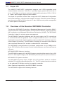
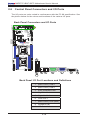
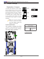
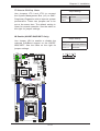
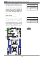
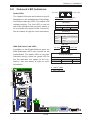
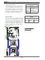
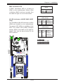
Front Control Panel
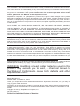
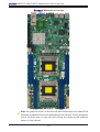
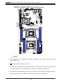
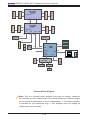
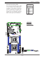
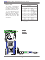
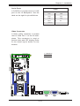
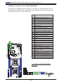
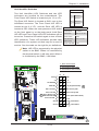
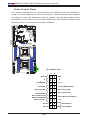
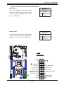
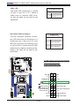
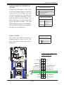
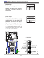
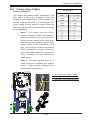
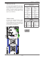
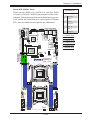
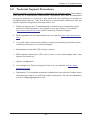
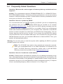
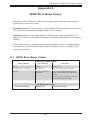
JF1 contains header pins for various buttons and indicators that are normally located on a control panel at the front of the chassis. These connectors are designed
specifically for use with Supermicro's server chassis. See the figure below for the
descriptions of the various control panel buttons and LED indicators. Refer to the
following section for descriptions and pin definitions.
JIB1
VGA
JBR1
LEM1
COM1
IPMI_LAN
JPL1
JPG1
T-SGPIO1
JVRM_I2C2
LE1
I-SATA5 I-SATA2
I-SATA4 I-SATA1
I-SATA3 I-SATA0
JBT1
X9DRT-F
JIPMB1
JVRM_I2C1
BIOS
USB2
PCH
C602J
JPB1
BMC
JBAT1
LAN
CTRL
IB
CTRL
JPTM1
InfiniBand
JPME1
LEB2
LEB1
JWD1
UID JI2C2 JPME2 CPU1 PCI-E 3.0 x16
SW1JI2C1
LAN2 LAN1 USB0/1
LE2
Rev. 1.01A
P1-DIMMC1
P1-DIMMD1
P1-DIMMB1
P1-DIMMA1
JSD1
CPU1
CLOSE 1st
Processor
#1
OPEN 1st
CPU2
CLOSE 1st
JF1
FPCTRL
P2-DIMME1
P2-DIMMF1
Fan3
J24 (20-Pin PWR)
OPEN 1st
P2-DIMMH1
P2-DIMMG1
JP8
(4-Pin PWR)J23 (20-Pin PWR)
Fan1
Processor
#2
JF1 Header Pins
Fan4JPI2C1
20
19
Ground
NMI
X
X
3.3 V
FP PWRLED
ID_UID_SW/3/3V Stby
HDD LED
NIC1 Link LED
NIC1 Activity LED
NIC2 Link LED
NIC2 Activity LED
Blue+ (OH/Fan Fail/
PWR FaiL/UID LED)
Red+ (Blue LED Cathode)
Power Fail LED
3.3V
Ground
Ground
2
2-24
1
Reset
Reset Button
PWR
Power Button