1
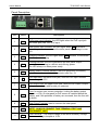
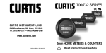
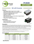
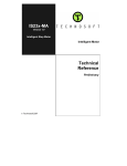
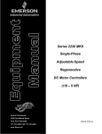
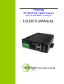
TYCON
TP-SCPOE-12XX Series
Solar & PoE Battery Charger
USER’S MANUAL
TYCON POWER SYSTEMS
User’s Manual
TP-SCPOE-12XX Series
Features:
Battery Polarity Reverse Protection
Battery Over Charge Protection
Battery Over Discharge Protection
Solar Panel Polarity Reverse Protection
Solar Panel Over Charge Protection
Output Short Circuit Protection
Output Over Voltage Protection
POE Output Short Circuit Protection
POE Output Support 802.3af Function (TP-SCPOE-1248D)
Two Input method:
(1)Solar Panel (2)PoE Power source (Always Solar First.)
Up to Three Outputs
DIN Rail Mountable
User’s Manual
TP-SCPOE-12XX Series
Panel Description:
Item
Name
Descriptions
1
POE :
PoE power input indicator: the LED lights when the PoE input jack
(the lower jack) has 18V~57V input.
2
SOL :
Solar power input indicator: the LED lights when SOL terminal is
connecting to a solar panel and the solar panel input voltage is over
12V.
3
CHA :
Charging indicator: the LED lights when BAT terminal is connected
to battery and charging
4
LOA :
Loading indicator: the LED lights when the rear panel output
terminal is connecting to a device and offering power.
The LED always on when power ready.
5
REV :
Battery polarity reverse indicator: the LED lights when the battery
polarities are reversed. (detail description see Sec. 5.1
6
IN :
PoE Input Jack: the lower RJ45 jack, used for PoE input. Allowed
input voltage 18~57V
7
OUT :
PoE Output Jack: the upper RJ45 jack, used for PoE output; Output
voltage depends on what model you selected.
8
Fuse
Fuse: for output over current protection, limiting the battery output
current <= 10A. (If solar panel or PoE source is installed before the
battery, and if the polarities of battery are reversed, then the fuse will
be burnt.)
9
SOL :
Solar Panel Terminal: used to connect the solar panel.
10
BAT :
Battery terminal: used to connect the battery.
NOTE: ALWAYS CONNECT THIS TERMINAL FIRST AND
DISCONNECT LAST.
11
LOA :
Load Terminal: The output voltage is the same as battery voltage.
Maximum voltage clamped at 12.5V.
User’s Manual
TP-SCPOE-12XX Series
Operation Guide
NOTICE:
1. Connect the battery to the BAT terminal. Make sure the polarities are
correctly connected. Sequentially connect the solar panel to SOL terminal
and connect POE source to PoE input (lower) jack. (If solar panel or PoE
source is installed before the battery, and if the polarities of the battery be
reversed, then the fuse will be burnt.)
2. Make sure the battery is properly connected to the unit. If no battery is
connected, then the voltage at BAT terminal will be approx 13.8V
3. The solar panel cannot be used stand alone without battery connected.
4. When a solar panel and PoE input are connected to the charger, if the
voltage of solar panel is higher than 15V, then solar panel is always the
main power source of the charger.
5. When charge from solar panel, as the battery full and turn to floating
stage, the CHA light will start flash, when charge from PoE, as the battery
full, the CHA light will be turn off.
6. When battery connect to BAT terminal and with valid voltage, then the
LOA indicator will always light on even no load connected.
User’s Manual
TP-SCPOE-12XX Series
Electrical specifications
1.0 INPUT
1.1 Input Source types:
A. Solar Panel
B. POE
1.2 Input Voltage:
A. Solar Panel: 18V~36Vmax
B. POE: 18V~57V
2.0 OUTPUT
Model
TP-SCPOE-1212
TP-SCPOE-1218
TP-SCPOE-1224
TP-SCPOE-1248
TP-SCPOE-1248D
Output 1*
(at rear terminal)
12V/1.5A
(as Bat. Volt.)*
12V/1.5A
(as Bat. Volt.)*
12V/1.5A
(as Bat. Volt.)*
12V/1.5A
(as Bat. Volt.)*
12V/1.5A
(as Bat. Volt.)*
Output 2
(at upper RJ45)
12V/1.0A
(as Bat. Volt.)*
18V/1.67A
(regulated)
24V/1.25A
(regulated)
48V/0.625A
(regulated)
48V/0.35A
(regulated)
*maximum voltage clamped at 12.5V
3.0 Battery Charge Types:
A. Solar Panel: charge current depends on the wattage of the solar panel.
B. POE: fixed current, 2.6A max
4.0 Battery Types: 12V Lead Acid Battery
5.0 Protection:
5.1 Battery Polarity Reverse Protection:
If only battery connected to terminal, when the battery polarities were reversed,
the model will stop output and REV indicator light on.
When the battery be removed and re-connected to terminal, the function will be
disable, if there is PoE power sources connected, when the battery polarities
reversed, the fuse will be burnt.
5.2 Battery Over Discharge Protection:
Cuts off the load when the battery voltage is lower than 11V + 0.3V, and auto
recover when the battery voltage returns to 12 V + 0.3V
User’s Manual
TP-SCPOE-12XX Series
5.3 Battery Over Charge Protection:
Fuse control, over 10A, the fuse will be burnt.
5.4 Solar Panel Polarity Reverse Protection:
When solar panel polarities be reversed, the charger stop output, it won’t damage
the charger or end device
5.5 Solar Panel Over Charge Protection:
When charge current over 10A, the fuse will be burnt.
5.6 Output Short Circuit Protection:
When the rear output terminal or PoE output be short circuit, protection be active,
the product stop output and auto-recover when the terminal back to normal
connection.
5.7 Battery Output Current Limit:
The fuse will be burnt when battery output current over 10A
5.8 Load Output Voltage Limit:
The output voltage on the rear terminal normally is the same as battery, if the
battery voltage higher than 12.5V, the output voltage on the terminal will be
clamped at 12.5V. The PoE output of TP-SCPOE-1212 with the same limit.
6. GENERAL DESCRIPTION
6.1 Operation Temperature:
6.2 Storage Temperature:
6.3 Operation Humidity:
6.4 Cooling:
6.5 SIZE
-20 - +60 Degree
-40 - +85 Degree
5% - 90%
Free air cooling
150*118*40mm (L*W*H)
7. RJ45 Connected and pin out:
RJ-45 Input (Data & Power)
RJ-45 Output (Data & Power)
Pin
Symbol
Description
Symbol
Description
1
RX+
Data Receive
RX+
Data Receive
2
RX-
Data Receive
RX-
Data Receive
3
TX+
Data Transmit
TX+
Data Transmit
4
(-Vdc)_return +
Feeding power(+)
(-Vdc)_return +
Feeding power(+)
5
(-Vdc)_return +
Feeding power(+)
(-Vdc)_return +
Feeding power(+)
6
TX-
Data Transmit
TX-
Data Transmit
7
-Vdc
Feeding power(-)
-Vdc
Feeding power(-)
8
-Vdc
Feeding power(-)
-Vdc
Feeding power(-)