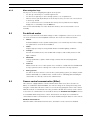
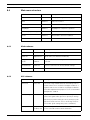
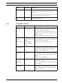
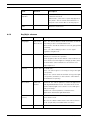
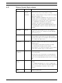
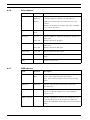
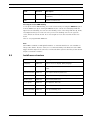
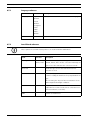
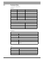
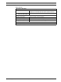
1
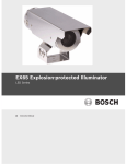
EX65 Explosion-protected Camera
VEN-650 Series
en
Instruction Manual
EX65 Explosion-protected Camera
Table of Contents | en
3
Table of Contents
1
Safety
5
1.1
Safety precautions
5
1.2
Important safety instructions
5
1.3
Important notices
7
1.4
FCC & ICES compliance
9
1.5
UL Certification
10
1.6
Explosion Protected Certifications
10
1.7
Joint Information
11
1.8
Bosch notices
11
1.9
Warranty / Limitation of Liability
12
2
Description
13
2.1
Unpacking
13
2.2
Parts List
13
2.2.1
Parts Included with the Product
13
2.2.2
User-supplied Parts
13
3
Planning
14
3.1
Dimensional Drawings
14
3.2
Initial Preparations
15
4
Installation
16
5
Connections
17
5.1
Power Cable Requirements
17
5.1.1
Wire Distance Guide
17
5.2
Coax Cable Requirements
17
5.3
Alarm Cable Requirements
18
5.4
Fiber Optic Cable Requirements
18
5.5
Making the Connections
18
6
Configuration
20
7
Mounting
22
7.1
Mounting the EX65
22
7.2
Installing the Sunshield
23
Bosch Security Systems, Inc.
Instruction Manual
F.01U.412.061 | 1.0 | 2011.03
4
en | Table of Contents
8
EX65 Explosion-protected Camera
Operation
24
8.1
Menus
24
8.1.1
Top level menus
24
8.1.2
Menu navigation keys
25
8.2
Pre-defined modes
25
8.3
Camera control communication (Bilinx)
25
8.4
Main menu structure
26
8.4.1
Mode submenu
26
8.4.2
ALC submenu
26
8.4.3
Shutter/AGC submenu
27
8.4.4
Day/Night submenu
28
8.4.5
Enhance / Dynamic Engine submenu
29
8.4.6
Color submenu
30
8.4.7
VMD submenu
30
8.5
Install menu structure
31
8.5.1
Language submenu
32
8.5.2
Lens Wizard submenu
32
8.5.3
Synchronization submenu
33
8.5.4
Alarm I/O submenu
33
8.5.5
Connections submenu
33
8.5.6
Test signal submenu
34
8.5.7
Camera ID submenu
34
8.5.8
Privacy masking submenu
35
8.5.9
Defaults submenu
35
9
Troubleshooting
36
9.1
Camera Operation
36
10
Maintenance
37
10.1
Repairs
37
10.2
Transfer and Disposal
37
10.3
Removal of the Camera and Lens
37
10.4
Installation of the Camera and Lens
38
10.5
Back Focus Adjustment
38
10.6
Replacement of the Mounting Cradle
39
11
Technical Data
40
Glossary
42
F.01U.412.061 | 1.0 | 2011.03
Instruction Manual
Bosch Security Systems, Inc.
EX65 Explosion-protected Camera
Safety | en
1
Safety
1.1
Safety precautions
5
DANGER!
High risk: This symbol indicates an imminently hazardous situation such as “Dangerous
Voltage” inside the product.
If not avoided, this will result in an electrical shock, serious bodily injury, or death.
WARNING!
Medium risk: Indicates a potentially hazardous situation.
If not avoided, this could result in minor or moderate bodily injury.
CAUTION!
Low risk: Indicates a potentially hazardous situation.
If not avoided, this could result in property damage or risk of damage to the unit.
1.2
Important safety instructions
Read, follow, and retain for future reference all of the following safety instructions. Heed all
warnings on the unit and in the operating instructions before operating the unit.
1.
Cleaning - Unplug the unit from the outlet before cleaning. Follow any instructions
provided with the unit. Generally, using a dry cloth for cleaning is sufficient but a moist,
fluff-free cloth or leather shammy may also be used. Do not use liquid cleaners or aerosol
cleaners.
2.
Heat Sources - Do not install the unit near any heat sources such as radiators, heaters,
stoves, or other equipment (including amplifiers) that produce heat.
3.
Ventilation - Any openings in the unit enclosure are provided for ventilation to prevent
overheating and ensure reliable operation. Do not block or cover these openings. Do not
place the unit in an enclosure unless proper ventilation is provided, or the manufacturer's
instructions have been adhered to.
4.
Water - Do not use this unit near water (for example, near a bathtub, washbowl, sink,
laundry basket, in a damp or wet basement, near a swimming pool, in an outdoor
installation, or in any area classified as a wet location), unless it is completely installed
and sealed. To reduce the risk of fire or electrical shock, do not expose this unit to rain or
moisture, unless it is completely installed and sealed.
5.
Object and liquid entry - Never push objects of any kind into this unit through openings
as they may touch dangerous voltage points or short-out parts that could result in a fire
or electrical shock. Never spill liquid of any kind on the unit, unless it is completely
installed and sealed. Do not place objects filled with liquids, such as vases or cups, on
the unit, unless it is completely installed and sealed.
6.
Lightning - For added protection during a lightning storm, or when leaving this unit
unattended and unused for long periods, unplug the unit from the wall outlet and
disconnect the cable system. This will prevent damage to the unit from lightning and
power line surges.
7.
Controls adjustment - Adjust only those controls specified in the operating instructions.
Improper adjustment of other controls may cause damage to the unit. Use of controls or
adjustments, or performance of procedures other than those specified, may result in
hazardous radiation exposure.
Bosch Security Systems, Inc.
Instruction Manual
F.01U.412.061 | 1.0 | 2011.03
6
en | Safety
EX65 Explosion-protected Camera
8.
Overloading - Do not overload outlets and extension cords. This can cause fire or
electrical shock.
9.
Power supply cord and plug protection - Protect the power supply cord and plug from
foot traffic, being pinched by items placed upon or against them at electrical outlets, and
its exit from the unit. For units intended to operate with 230 VAC, 50 Hz, the power
supply cord must comply with the latest versions of IEC 60227. For units intended to
operate with 120 VAC, 60 Hz, the power supply cord must comply with the latest
versions of UL 62 and CSA 22.2 No.49.
10. Power disconnect - Units have power supplied to the unit whenever the power cord is
inserted into the power source. The power cord plug is the main power disconnect
device for switching off the voltage for all units.
11. Power sources - Operate the unit only from the type of power source indicated on the
label. Before proceeding, be sure to disconnect the power from the cable to be installed
into the unit.
–
–
For battery powered units, refer to the operating instructions.
For external power supplied units, use only the recommended or approved power
supplies.
–
For limited power source units, this power source must comply with EN60950.
Substitutions may damage the unit or cause fire or shock.
–
For 24 VAC units, voltage applied to the unit's power input should not exceed ±10%,
or 28 VAC. User-supplied wiring must comply with local electrical codes (Class 2
power levels). Do not ground the supply at the terminals or at the unit's power
supply terminals.
–
If unsure of the type of power supply to use, contact your dealer or local power
company.
12. Servicing - Do not attempt to service this unit yourself. Opening or removing covers may
expose you to dangerous voltage or other hazards. Refer all servicing to qualified service
personnel.
13. Damage requiring service - Unplug the unit from the main AC power source and refer
servicing to qualified service personnel when any damage to the equipment has
occurred, such as:
–
the power supply cord or plug is damaged;
–
exposure to moisture, water, and/or inclement weather (rain, snow, etc.);
–
liquid has been spilled in or on the equipment;
–
an object has fallen into the unit;
–
unit has been dropped or the unit cabinet is damaged;
–
unit exhibits a distinct change in performance;
–
unit does not operate normally when the user correctly follows the operating
instructions.
14. Replacement parts - Be sure the service technician uses replacement parts specified by
the manufacturer, or that have the same characteristics as the original parts.
Unauthorized substitutions may cause fire, electrical shock, or other hazards.
15. Safety check - Safety checks should be performed upon completion of service or repairs
to the unit to ensure proper operating condition.
16. Installation - Install in accordance with the manufacturer's instructions and in
accordance with applicable local codes.
F.01U.412.061 | 1.0 | 2011.03
Instruction Manual
Bosch Security Systems, Inc.
EX65 Explosion-protected Camera
Safety | en
7
17. Attachments, changes or modifications - Only use attachments/accessories specified by
the manufacturer. Any change or modification of the equipment, not expressly approved
by Bosch, could void the warranty or, in the case of an authorization agreement, authority
to operate the equipment.
EU Directives covered by this declaration:
72/9/EC Low Voltage Directives
89/336/EEC Electromagnetic Compatibility Directive
1.3
Important notices
Accessories - Do not place this unit on an unstable stand, tripod, bracket, or mount. The unit
may fall, causing serious injury and/or serious damage to the unit. Use only with the cart,
stand, tripod, bracket, or table specified by the manufacturer. When a cart is used, use
caution and care when moving the cart/apparatus combination to avoid injury from tip-over.
Quick stops, excessive force, or uneven surfaces may cause the cart/unit combination to
overturn. Mount the unit per the manufacturer's instructions.
All-pole power switch - Incorporate an all-pole power switch, with a contact separation of at
least 3 mm in each pole, into the electrical installation of the building. If it is needed to open
the housing for servicing and/or other activities, use this all-pole switch as the main
disconnect device for switching off the voltage to the unit.
Camera signal - Protect the cable with a primary protector if the camera signal is beyond 140
feet, in accordance with NEC800 (CEC Section 60).
Coax grounding:
–
–
Ground the cable system if connecting an outside cable system to the unit.
Connect outdoor equipment to the unit's inputs only after this unit has had its grounding
plug connected to a grounded outlet or its ground terminal is properly connected to a
ground source.
–
Disconnect the unit's input connectors from outdoor equipment before disconnecting
the grounding plug or grounding terminal.
–
Follow proper safety precautions such as grounding for any outdoor device connected to
this unit.
U.S.A. models only - Section 810 of the National Electrical Code, ANSI/NFPA No.70, provides
information regarding proper grounding of the mount and supporting structure, grounding of
the coax to a discharge unit, size of grounding conductors, location of discharge unit,
connection to grounding electrodes, and requirements for the grounding electrode.
Disposal - Your Bosch product was developed and manufactured with high-quality material
and components that can be recycled and reused. This symbol means that electronic and
electrical appliances, which have reached the end of their working life, must be collected and
disposed of separately from household waste material. Separate collecting systems are
usually in place for disused electronic and electrical products. Please dispose of these units
at an environmentally compatible recycling facility, per European Directive 2002/96/EC.
Electronic Surveillance - This device is intended for use in public areas only. U.S. federal law
strictly prohibits surreptitious recording of oral communications.
Environmental statement - Bosch has a strong commitment towards the environment. This
unit has been designed to respect the environment as much as possible.
Electrostatic-sensitive device - Use proper CMOS/MOS-FET handling precautions to avoid
electrostatic discharge.
NOTE: Wear required grounded wrist straps and observe proper ESD safety precautions when
handling the electrostatic-sensitive printed circuit boards.
Bosch Security Systems, Inc.
Instruction Manual
F.01U.412.061 | 1.0 | 2011.03
8
en | Safety
EX65 Explosion-protected Camera
Fuse rating - For protection of the device, the branch circuit protection must be secured with
a maximum fuse rating of 16A. This must be in accordance with NEC800 (CEC Section 60).
Moving - Disconnect the power before moving the unit. Move the unit with care. Excessive
force or shock may damage the unit and the hard disk drives.
Outdoor signals - The installation for outdoor signals, especially regarding clearance from
power and lightning conductors and transient protection, must be in accordance with NEC725
and NEC800 (CEC Rule 16-224 and CEC Section 60).
Permanently connected equipment - Incorporate a readily accessible disconnect device
external to the equipment.
Pluggable equipment - Install the socket outlet near the equipment so it is easily accessible.
Power resupply - If the unit is forced to power down due to exceeding the specified operating
temperatures, disconnect the power cord, wait for at least 30 seconds, and then reconnect
the power cord.
Power lines - Do not locate the unit near overhead power lines, power circuits, or electrical
lights, nor where it may contact such power lines, circuits, or lights.
SELV - All the input/output ports are Safety Extra Low Voltage (SELV) circuits. SELV circuits
should only be connected to other SELV circuits.
Because the ISDN circuits are treated like telephone-network voltage, avoid connecting the
SELV circuit to the Telephone Network Voltage (TNV) circuits.
System ground/Safety ground
System (video) ground is indicated by the symbol
.
Safety (power) ground is indicated by the symbol
.
The system ground is only used to comply with safety standards or installation practices in
certain countries. Bosch does not recommend connecting system ground to safety ground
unless it is explicitly required. However, if the system ground and safety ground are
connected and grounding loops are causing interference in the video signal, use an isolation
transformer (available separately from Bosch).
CAUTION!
Connecting System ground to Safety ground may result in ground loops that can disrupt the
CCTV system.
Unit grounding - For mounting the unit in potentially damp environments, ensure to ground
the system using the ground connection of the power supply connector (see
Section 5.1 Power Cable Requirements, page 17).
Video loss - Video loss is inherent to digital video recording; therefore, Bosch Security
Systems cannot be held liable for any damage that results from missing video information. To
minimize the risk of lost digital information, Bosch Security Systems recommends multiple,
redundant recording systems, and a procedure to back up all analog and digital information.
F.01U.412.061 | 1.0 | 2011.03
Instruction Manual
Bosch Security Systems, Inc.
EX65 Explosion-protected Camera
1.4
Safety | en
9
FCC & ICES compliance
FCC Information
(U.S.A. and Canadian Models Only)
This equipment has been tested and found to comply with the limits for a Class B digital
device, pursuant to part 15 of the FCC Rules. These limits are designed to provide reasonable
protection against harmful interference in a residential installation. This equipment
generates, uses, and can radiate radio frequency energy and, if not installed and used in
accordance with the instructions, may cause harmful interference to radio communications.
However, there is no guarantee that interference will not occur in a particular installation. If
this equipment does cause harmful interference to radio or television reception, which can be
determined by turning the equipment off and on, the user is encouraged to try to correct the
interference by one or more of the following measures:
–
reorient or relocate the receiving antenna;
–
increase the separation between the equipment and receiver;
–
connect the equipment into an outlet on a circuit different from that to which the
receiver is connected;
–
consult the dealer or an experienced radio/TV technician for help.
Intentional or unintentional modifications, not expressly approved by the party responsible
for compliance, shall not be made. Any such modifications could void the user's authority to
operate the equipment. If necessary, the user should consult the dealer or an experienced
radio/television technician for corrective action.
The user may find the following booklet, prepared by the Federal Communications
Commission, helpful: How to Identify and Resolve Radio-TV Interference Problems. This booklet
is available from the U.S. Government Printing Office, Washington, DC 20402, Stock No. 004000-00345-4.
Informations FCC et ICES
(modèles utilisés aux États-Unis et au Canada uniquement)
Suite à différents tests, cet appareil s'est révélé conforme aux exigences imposées aux
appareils numériques de classe B, en vertu de la section 15 du règlement de la Commission
fédérale des communications des États-Unis (FCC), et en vertu de la norme ICES-003 d'Industrie
Canada. Ces exigences visent à fournir une protection raisonnable contre les interférences
nuisibles lorsque l'appareil est utilisé dans le cadre d'une installation résidentielle. Cet
appareil génère, utilise et émet de l'énergie de radiofréquences et peut, en cas d'installation
ou d'utilisation non conforme aux instructions, engendrer des interférences nuisibles au
niveau des radiocommunications. Toutefois, rien ne garantit l'absence d'interférences dans
une installation particulière. Il est possible de déterminer la production d'interférences en
mettant l'appareil successivement hors et sous tension, tout en contrôlant la réception radio
ou télévision. L'utilisateur peut parvenir à éliminer les interférences éventuelles en prenant
une ou plusieurs des mesures suivantes:
–
Modifier l'orientation ou l'emplacement de l'antenne réceptrice;
–
Éloigner l'appareil du récepteur;
–
Brancher l'appareil sur une prise située sur un circuit différent de celui du récepteur;
–
Consulter le revendeur ou un technicien qualifié en radio/télévision pour obtenir de
l'aide.
Toute modification apportée au produit, non expressément approuvée par la partie
responsable de l'appareil, est strictement interdite. Une telle modification est susceptible
d'entraîner la révocation du droit d'utilisation de l'appareil.
La brochure suivante, publiée par la Commission fédérale des communications (FCC), peut
s'avérer utile : How to Identify and Resolve Radio-TV Interference Problems (Comment identifier
et résoudre les problèmes d’interférences de radio et de télévision). Cette brochure est
disponible auprès du U.S. Government Printing Office, Washington, DC 20402, États-Unis,
sous la référence n° 004-000-00345-4.
Bosch Security Systems, Inc.
Instruction Manual
F.01U.412.061 | 1.0 | 2011.03
10
1.5
en | Safety
EX65 Explosion-protected Camera
UL Certification
Disclaimer
Underwriter Laboratories Inc. (“UL”) has not tested the performance or reliability of the
security or signaling aspects of this product. UL has only tested fire, shock and/or casualty
hazards as outlined in UL's Standard(s) for Safety for Closed Circuit Television Equipment, UL
2044. UL Certification does not cover the performance or reliability of the security or signaling
aspects of this product.
UL MAKES NO REPRESENTATIONS, WARRANTIES, OR CERTIFICATIONS WHATSOEVER
REGARDING THE PERFORMANCE OR RELIABILITY OF ANY SECURITY OR SIGNALINGRELATED FUNCTIONS OF THIS PRODUCT.
Disclaimer
Underwriter Laboratories Inc. (“UL”) has not tested the performance or reliability of the
security or signaling aspects of this product. UL has only tested fire, shock and/or casualty
hazards as outlined in UL's Standard(s) for Safety for Information Technology Equipment, UL
60950-1. UL Certification does not cover the performance or reliability of the security or
signaling aspects of this product.
UL MAKES NO REPRESENTATIONS, WARRANTIES, OR CERTIFICATIONS WHATSOEVER
REGARDING THE PERFORMANCE OR RELIABILITY OF ANY SECURITY OR SIGNALINGRELATED FUNCTIONS OF THIS PRODUCT.
1.6
Explosion Protected Certifications
Camera for Use in Hazardous Locations
Bosch Security Systems B.V.
NEN-65 Camera models
12-24 VDC, 12-24 VAC, Class 2, 20 watts (1.5A Maximum)
Control number 3RR9
Class I, Groups C, and D; Class II, Groups E, F, and G; Class III
Class I, Zone 1, AEx d IIB T6; Ex d IIB T6 X
AEx tD 21 T85°C
DIP DIP A21 Ta85°C X
Type 4X, IP67
DEMKO 10 ATEX 0948139X
CE 0344 II 2 GD
Ex d IIB T6 Gb
Ex tb IIIC T85°C Db IP67
-50 °C < Ta < 60 °C
F.01U.412.061 | 1.0 | 2011.03
Instruction Manual
Bosch Security Systems, Inc.
EX65 Explosion-protected Camera
1.7
Safety | en
11
Joint Information
Joint-Threaded (All Models)
Designation Pitch Full Threads Depth of
Back Cover of Junction Box to
M 103
(mm) Engaged
2
7
Engagement (mm)
14.5
Connection Plate of Junction Box
Housing to Connection Plate of
M 103
2
7
18.5
Junction Box
Supply Opening Blanking Element to
3/4-14 NPT N/A
5
N/A
M 103
8
18.5
Connection Plate of Junction Box
(four openings provided)
Housing and Front Cover/Fascia
2
To obtain more information about the flameproof joints, please contact Bosch Security
Systems.
WARNING!
To reduce the risk of ignition of hazardous atmospheres, conduit runs must have a sealing
fitting connected to the wall of the enclosure.
WARNING!
DO NOT OPEN WHEN AN EXPLOSIVE ATMOSPHERE MAY BE PRESENT.
1.8
Bosch notices
Copyright
This manual is the intellectual property of Bosch Security Systems and is protected by
copyright. All rights reserved.
Trademarks
All hardware and software product names used in this document are likely to be registered
trademarks and must be treated accordingly.
NOTE:
This manual has been compiled with great care and the information it contains has been
thoroughly verified. The text was complete and correct at the time of printing. The ongoing
development of the products may mean that the content of the user guide can change without
notice. Bosch Security Systems accepts no liability for damage resulting directly or indirectly
from faults, incompleteness or discrepancies between the user guide and the product
described.
More information
For more information, please contact the nearest Bosch Security Systems location or visit
www.boschsecurity.com.
Bosch Security Systems, Inc.
Instruction Manual
F.01U.412.061 | 1.0 | 2011.03
12
1.9
en | Safety
EX65 Explosion-protected Camera
Warranty / Limitation of Liability
The EX65 has a 3 year warranty.
BOSCH Security Systems warrants that its products, at the time of shipment by BOSCH
Security Systems, are free from defect in material or workmanship under normal use and
service for the respective warranty periods specified in the applicable Price Schedule or as
otherwise published.
To assure conformance with operating limitations, Buyer should refer to the applicable data
sheet.
The warranty is void (i) if the Product is not operated in conformance with installation,
environmental, mechanical or electrical requirements, or within thermal stress limits, or (ii) to
the extent that any malfunction is the result of misuse, abuse, vandalism, neglect, improper
installation or application, alteration, accident, or negligence in use, storage, transportation,
or handling or if the original identification markings on the product have been removed,
defaced or altered, lightning, electricity, water, fire, environment or other hazard, or act of
God, or other impact outside of normal operating guidelines.
The foregoing warranty is subject to Buyer’s (i) promptly written claim and (ii) timely
provision to BOSCH Security Systems of an opportunity to inspect and test the Product
claimed to be defective. Such inspection may be on Buyer’s premises and/or BOSCH Security
Systems may request the return of the Product at Buyer’s expense. However, BOSCH Security
Systems shall not be responsible for packing, inspection, or labor costs in connection with the
return of Product. No Product shall be accepted for warranty service that is not accompanied
by a Return Authorization issued by BOSCH.
The liability of BOSCH Security Systems hereunder or otherwise is solely and exclusively
limited to replacement (new or refurbished Product), repair, or credit of the amortized
purchase price, as BOSCH Security may elect, for any Product which is returned by Buyer
during the applicable warranty period, or services for which timely notice of defect has been
given by Buyer, and which are found by BOSCH Security to be subject to adjustment under
this warranty.
BOSCH Security System’s warranty shall not be enlarged, diminished, or affected by, and no
obligation or liability shall arise or grow out of BOSCH Security’s rendering or technical
advice, facilities, or services in connection with Buyer’s order to the products furnished
hereunder.
For more information about the warranty on this product, see the Warranty Repair section on
Bosch’s Customer Care web page at www.boschsecurity.us/en-us/Service/CustomerCare.
F.01U.412.061 | 1.0 | 2011.03
Instruction Manual
Bosch Security Systems, Inc.
EX65 Explosion-protected Camera
2
Description | en
13
Description
The EX65 Explosion Protected Camera is a high-performance, smart surveillance camera for
explosive environments. Utilizing Dinion 2X imaging, the camera offers unrivaled image quality
in the worst lighting conditions. Electropolished 316L stainless steel construction ensures the
ultimate environmental protection available today. A single pre-assembled unit with an
integrated junction box, the EX65 is designed to be easy to install. Through any of the four (4)
3/4 in. conduit entries (M20 adapter included with PAL versions), connections are made to
the convenient terminal block; there is also space for any additional wiring. Also accessible
through the junction box is the optional fiber optic module that provides versatility for longer
cable runs where electromagnetic interference is a concern.
2.1
Unpacking
This electronic equipment should be unpacked and handled carefully. If an item appears to
have been damaged in shipment, notify the shipper immediately.
Verify that all the parts listed in the Parts List below are included. If any items are missing,
notify your Bosch Security Systems Sales or Customer Service Representative.
The original packing carton is the safest container in which to transport the unit and must be
used if returning the unit for service. Save it for possible future use.
2.2
Parts List
2.2.1
Parts Included with the Product
2.2.2
Quantity
Item
1
EX65 Explosion Protected Camera
1
Sunshield
4
M4 bolts with washers for sunshield
1
1.5 mm hex key
1
Multi-use tool
1
Instruction Manual
User-supplied Parts
Quantity Item
3
M6 x 1.0 x 16 mm bolts with lock washers
1
Bottle of Jet-Lube® NCS-30 grease (as needed)
1
Tube of Molykote® BG 20 grease (as needed)
1
Tube of LA-CO Slic-Tite® Paste with PTFE (as needed)
Bosch Security Systems, Inc.
Instruction Manual
F.01U.412.061 | 1.0 | 2011.03
14
3
en | Planning
EX65 Explosion-protected Camera
Planning
Refer to the information below before installing the unit. This section provides dimensional
information and guidelines to help plan your installation.
3.1
Dimensional Drawings
135
5.30
128
5.04
102
4.01
116
4.57
125
4.93
Figure 3.1
Front View
471
18.54
114
4.50
208
8.18
90°
100
3.94
381
15.01
Figure 3.2
F.01U.412.061 | 1.0 | 2011.03
Side View
Instruction Manual
Bosch Security Systems, Inc.
EX65 Explosion-protected Camera
Planning | en
15
3/4-in. NPTX 4
6.6
0.26
Figure 3.3
3.2
71°
60.0
Ø 2.36
Bottom View
Initial Preparations
–
Determine the operating voltage at the installation site. The circuit board automatically
configures for 12 VDC or 24 VAC operation. The unit can receive an input voltage range of
10.5 VDC to 40 VDC or 12 VAC to 28 VAC without damage, but it is recommend to stay
within the voltage range specified in Section 1.6 Explosion Protected Certifications.
–
All units have been tested prior to shipment. It is advisable to check the unit’s operation
before installation.
CAUTION!
It is recommended that the installer wear an ESD strap or discharge any static electricity to
ground before handling any electronic components.
Bosch Security Systems, Inc.
Instruction Manual
F.01U.412.061 | 1.0 | 2011.03
16
4
en | Installation
EX65 Explosion-protected Camera
Installation
This chapter details the installation guidelines for the EX65. It is important that you consider
these steps.
WARNING!
Do not apply power to the unit in an explosive environment unless the housing is fully
installed, the front and back caps are tightened, and all openings are appropriately plugged
and sealed. Disconnect power before servicing or disassembling the unit.
Based on the explosion protected requirements of the installation location, determine the
appropriate installation method and follow all local guidelines and laws. It is important to
keep the following in mind during installation:
–
It is advisable to set up the camera lens prior to installation as lens adjustments require
the unit to be opened, see Section 6 Configuration, page 20.
–
The front and back end caps of the unit must be removed for access to the internal
electronics or to adjust the lens. The set screws on the caps are tightened at the factory.
It is easier to remove the front end cap with the sunshield removed.
–
When tightening the end caps, ensure that the threads are clean and lubricated with JetLube® NCS-30 grease or equivalent.
–
Before tightening the end caps, ensure that the o-rings are clean and lubricated with
Molykote® BG 20 grease (from Dow Corning) or equivalent.
–
Ensure that all 3/4-in. NPT plugs are securely tightened in the 3/4-in. NPT conduit
openings and sealed with LA-CO Slic-Tite® Paste with PTFE, apply per manufacturer’s
instructions on the label.
–
Ensure that the unit is wired and sealed appropriately either with a conduit seal or a
gland and cable rated for the intended environment. Use LA-CO Slic-Tite® Paste with
PTFE thread sealant on all conduit or gland threads.
–
Carefully follow all manufacturers’ instructions for applying grease and paste products.
–
If cable glands are used, they shall be certified for ATEX and IECEx certified for Ex d IIB
Gb and Ex tb IIIB Db IP67 rated at least 85 °C.
–
All unused conduit openings shall have a 3/4-14 in. NPT stopping plug certified for Class
I, Groups C, and D; Class II, Groups E, F, and G; and Class III; Class I, Zone 1, AEx d IIB;
AEx tD 21; Ex d IIB; DIP A21 hazardous locations, as supplied with the unit.
–
Unused conduit openings shall be closed with the provided conduit plug.
–
The maximum surface temperature of the unit will never reach 85 °C when used
–
If starting up the unit below -40 °C, there may be a delay between when power is applied
throughout the ambient operating range of –50 °C to 60 °C (–58 °F to 140 °F).
to the camera and when video output is available.
–
The joint between the junction box and housing is secured by a thread locker for
permanent securement. This joint shall not be removed because there may be damage to
the flamepath.
–
The device was subjected to the resistance to impact test at 2 J. It shall be installed
–
For ambient temperatures below –10 °C, use field wiring suitable for the minimum
where it will not be subjected to impact.
ambient temperature.
F.01U.412.061 | 1.0 | 2011.03
Instruction Manual
Bosch Security Systems, Inc.
EX65 Explosion-protected Camera
5
Connections | en
17
Connections
All required connections are accessible by removing the end cap conveniently located in the
rear of the EX65.
NOTICE!
Take care not to drop the end caps to prevent damage to the cap threads.
5.1
Power Cable Requirements
WARNING!
Before proceeding, disconnect the power from the power supply cable. Ensure that the
voltage of the unit matches the voltage and type of the power supply being used.
Connect power from a 12 - 24 VAC or 12 - 24 VDC class 2 power supply. Use AWG 16 to 22
stranded wire or AWG 16 to 26 solid wire; cut back 5 mm (0.2 in.) of insulation.
Cable size
Stranded wire: AWG 16 to 22
Solid wire: AWG 16 to 26
5.1.1
Cable shape
Round
Conductors
2-conductor version
Environmental
Outdoor rated
Wire Distance Guide
This table lists the maximum wire distances for 14, 16, and 18 AWG wires connected to a
24 VAC camera.
Watts 14 AWG (2.5 mm)
All Models
5.2
20
16 AWG (1.5 mm)
18 AWG (1.0 mm)
289 m
182 m
114 m
(949 ft)
(597 ft)
(376 ft)
Coax Cable Requirements
Cable type
RG-59/U for runs < 300 m (1000 ft)
RG-11/U for runs < 600 m (2000 ft)
Cable size
Outside diameter between 4.6 mm to 7.9 mm (0.181 in. to 0.312 in.)
Cable shape
Round
Shield
> 93% braided copper shield
Center conductor
Stranded copper center
DC resistance
< 15 Ohm/1000 m (RG-59/U)
< 6 Ohm/1000 m (RG-11/U)
Cable impedance
75 Ohm
Agency rating
UL
Environmental
Outdoor rated
Temperature rating > 80 degrees C
Sources
Bosch Security Systems, Inc.
Belden 9259
Instruction Manual
F.01U.412.061 | 1.0 | 2011.03
18
5.3
en | Connections
EX65 Explosion-protected Camera
Alarm Cable Requirements
The EX65 terminal block contains one Alarm Out connection.
Max. wire diameter
AWG 22-28 for both stranded and solid
Alarm output relay
Max voltage 30 VAC or +40 VDC. Max 0.5 A continuous, 10 VA.
switching capability
5.4
Fiber Optic Cable Requirements
Certain EX65 models allow you to transmit video over an analog multimode fiber instead of
using a coax cable.
Multimode
5.5
Fiber Type
50/125 µm, 62.5/125 µm, low loss multimode glass fiber
Maximum Distance
4 km (2.5 miles)
Video Bandwidth
5 Hz to 10 MHz
Wavelength
850 nm
Requirement
Bosch LTC 4629 Fiber Receiver at controller end of system
Terminal Connector
ST
Making the Connections
Refer to the following illustration when making connections:
Figure 5.1
1
2
3
4
5
6
7
F.01U.412.061 | 1.0 | 2011.03
EX65 Cable Connection Terminators
Terminals for incoming power and outgoing alarm cables
Internal camera use. DO NOT connect any cables to these terminals
Power In (12–24 VDC/12–24 VAC)
Power In (12–24 VDC/12–24 VAC)
Alarm Out
Alarm Out
BNC connector or Fiber Optic ST connector (dependent on model)
Instruction Manual
Bosch Security Systems, Inc.
EX65 Explosion-protected Camera
Connections | en
19
CAUTION!
Connections to the terminal block must be made to the terminals on the left side. Do not
make connections to the terminals on the right side of the block.
1.
Loosen the set screws on the rear end cap using the supplied hex key. Loosen the rear
end cap using the supplied multi-use tool. To prevent damage to the o-ring, for every half
turn counterclockwise turn back one quarter-turn clockwise. (see Figure 5.2 below).
Note: To prevent damage to the cap threads, take care not to drop the end caps.
Figure 5.2 Removal of end cap with multi-use tool
2.
Unscrew the rear end cap by hand.
3.
Feed power, alarm (if used), and video cables through any one of the four 3/4-in. conduit
entries.
4.
Connect one lead of the power cable to terminal 3 and the other lead to terminal 4.
Note: The power in terminals are polarity insensitive.
5.
6.
Connect the alarm out cables to terminal 5 and 6.
For standard video models, connect the video coax cable with a male BNC connector to
terminal 7.
Note: A UTP adapter (VDA-455UTP) is available as an optional accessory to allow a UTP
video cable to be connected to the BNC connector.
7.
For fiber optic video models, connect a terminated fiber optic cable to the female ST
connector.
8.
Make sure that the o-ring and threads are clean and greased before replacing the rear
end cap. Use the supplied multi-use tool to tighten the rear end cap. Ensure that the oring is properly seated. After tightening, ensure that there is no gap between the cap and
the body of the housing.
9.
Bosch Security Systems, Inc.
Tighten the set screws on the rear end cap using the supplied hex key.
Instruction Manual
F.01U.412.061 | 1.0 | 2011.03
20
6
en | Configuration
EX65 Explosion-protected Camera
Configuration
Making Adjustments to the Camera Lens
You must remove the front end cap to make lens adjustments. You may need to remove the
inner bracket assembly for easier access to the lens controls.
Camera adjustments may be done remotely via the Bilinx “through the coax” interface or
directly on the camera itself by removing the inner bracket assembly. When the Bilinx
communications link is active, the buttons on the cameras are disabled. See
Section 8 Operation, page 24, for more information.
1.
Loosen the set screw on the front end cap using the supplied hex key.
Note: Take care not to drop the end caps to prevent damage to the cap threads.
2.
Loosen the front end cap using the supplied multi-use tool. To prevent damage to the oring, for every half turn counterclockwise turn back one quarter turn clockwise.
3.
Unscrew the front end cap by hand. You may need to remove the sunshield to remove the
front end cap more easily.
4.
To adjust the lens and to access the Dinion menu buttons:
a.
Using the supplied multi-use tool, loosen the three (3) bolts (Item 1, below) that
hold the inner mounting bracket assembly.
F.01U.412.061 | 1.0 | 2011.03
Instruction Manual
Bosch Security Systems, Inc.
EX65 Explosion-protected Camera
b.
Configuration | en
21
Pull the assembly out of the housing.
Figure 6.1 Camera pulled from housing
1
2
3
5.
6.
7.
8.
9.
Inner mounting bracket assembly
Dinion 2X camera
Dinion menu buttons
Loosen the lens set screws for focus/zoom adjustments.
Use the set screw marked N <— —> ∞ to adjust image focus.
–
Turn the set screw to the left to focus toward (N) (near) (zoom in).
–
Turn the set screw to the right to focus toward (F) (far) / infinite (∞) (zoom out).
Use the set screw marked T <— —> W to adjust the telephoto or wide-angle settings.
–
Turn the set screw to the left for a telephoto (tight) focal length
–
Turn the set screw to the right for a wider focal length.
Re-tighten the lens set screws after focus adjustments have been completed.
To make adjustments using the Dinion 2X Main menu for a more detailed setup, refer to
Section 8 Operation, page 24.
10. Slide the inner mounting bracket assembly back into the camera housing and ensure that
it locks into place at the back of the housing. The bracket should not rotate and the
camera should be completely level.
11. Using a 10 mm wrench, tighten the three (3) bolts to secure the inner mounting bracket
assembly.
12. Make sure that the o-ring and threads are clean and greased before replacing the front
end cap. Use the supplied multi-use tool to tighten the rear end cap. Ensure that the Oring is properly seated. After tightening, ensure that there is no gap between the cap and
the body of the housing.
13. Tighten the set screw on the front end cap using the supplied hex key.
Bosch Security Systems, Inc.
Instruction Manual
F.01U.412.061 | 1.0 | 2011.03
22
en | Mounting
EX65 Explosion-protected Camera
7
Mounting
7.1
Mounting the EX65
Follow all local codes with respect to the wiring and installation of explosion protected
housings.
CAUTION!
Ensure the selected location is protected from falling objects, accidental contact with moving
objects, and unintentional interference from personnel. Follow all applicable building codes.
The following installation guidelines must be followed:
–
Locate the unit such that it cannot be easily interfered with, either intentionally or
accidentally.
–
Select mounting hardware and a mounting surface capable of supporting the combined
weight of the equipment under all expected conditions of vibration and temperature.
–
Secure all cabling.
The EX65 can be mounted to a compatible Bosch bracket with M6 bolts or any purpose-built
bracket using M6 or 1/4 in.–20 bolts. Ensure that a fabricated bracket is capable of
supporting at least three times the weight of the system. See Figure 7.1 below to match the
mounting cradle holes.
3/4-in. NPTX 4
6.6
0.26
Figure 7.1
1.
71°
60.0
Ø 2.36
Bottom View with Mounting Cradle detail
Choose a mounting surface and, if needed, prepare the surface by pre-drilling and
tapping three M6 x 1.0 x 20 mm holes in a line that are 30 mm apart center to center and
in line with the desired surveillance target (see Figure 7.1).
2.
Allocate three stainless steel M6 x 1.0 x 16 mm bolts with lock washers and ensure that
the mounting surface and the threads of bolts are clean and free of debris.
3.
Optionally apply a few drops of a medium strength thread locking agent to the bolts per
the manufacturer’s instructions.
4.
Secure the mounting cradle (see Figure 7.1, item 1) to the mounting surface with the
M6 x 1.0 x 16 mm bolts and lock washers using a 10 mm wrench or the supplied multiuse tool. Do not tighten fully.
F.01U.412.061 | 1.0 | 2011.03
Instruction Manual
Bosch Security Systems, Inc.
EX65 Explosion-protected Camera
5.
Mounting | en
23
Slightly loosen the six M6 bolts on both sides of the mounting cradle, using a 10mm
wrench or the supplied multi-use tool, and make directional adjustments to the EX65 so
that it is pointing at the desired surveillance target (see the graphics below).
6.
7.
Tighten all mounting bolts to 3 to 5 ft-lb (4.1 to 6.8 N·m).
Connect wiring as explained in Section 5 Connections, page 17, and follow all local
regulations and laws regarding explosion protected devices.
8.
Connect the ground cable, located on the bottom of the housing, to a suitable grounded
material (grounded conduit or a ground wire).
7.2
Installing the Sunshield
1.
Line up the mounting holes of the sunshield with the tapped holes in the body of the
EX65.
2.
Install the supplied M4 bolts through the sunshield bolt holes into the body of the unit
and tighten by hand.
3.
Tighten the supplied bolts to 1.5 ft/lb (2.0 N/m) using a 7 mm wrench or the supplied
multi-use tool.
Bosch Security Systems, Inc.
Instruction Manual
F.01U.412.061 | 1.0 | 2011.03
24
en | Operation
8
EX65 Explosion-protected Camera
Operation
The camera normally provides an optimal picture without the need for further adjustments.
Advanced set-up options are available in a menu system for getting the best results under
special circumstances. The camera implements your changes immediately so that before and
after settings are easily compared.
8.1
Menus
8.1.1
Top level menus
There are two upper level menus: the Main menu and the Install menu. Both menus have
functions that can be selected directly or submenus for more detailed set-up. The Main menu
allows you to select and set up the picture enhancement functions. The Install menu allows
you to set the installation settings. To access the menus, follow the steps below.
1.
Open the side door panel at the side of the camera.
Bos
ch
2.
Unlock the back focus locking button.
Bosch
3.
Locate the five navigation keys behind the side door panel.
Figure 8.1
Key
1
2
3
4
5
4.
Advanced camera setup keypad
Description
Up key
Right key
Down key
Left key
Menu/Select key (center)
Access the appropriate menu:
–
To access the Main menu, press and hold the center key for less than 1 second. The
Main menu appears on the monitor. If you are not happy with your changes, you can
always recall the default values for the mode.
–
F.01U.412.061 | 1.0 | 2011.03
To access the Install menu, press and hold the center key for mores than 2 seconds.
Instruction Manual
Bosch Security Systems, Inc.
EX65 Explosion-protected Camera
8.1.2
Operation | en
25
Menu navigation keys
Five keys are used for navigating through the menu system.
–
Use the up or down keys to scroll through a menu.
–
Use the left or right keys to move through options or to set parameters.
–
When in a menu, quickly double-press the menu/select key to restore the selected item
to its factory default.
–
To close all menus at once, hold down the menu/select key until the menu display
disappears or continually select the Exit item.
Some menus automatically close after about two minutes; other menus must be closed
manually.
8.2
Pre-defined modes
There are six pre-defined modes with settings to make configuration easier. You can select
one of the six modes in the Install/Mode submenu. The modes are defined as follows:
1.
24-hour
Default installation mode to provide stable pictures over a 24-hour period. These settings
are optimized for out-of-the-box installation.
2.
Traffic
Capture high-speed objects using default shutter in variable lighting conditions.
3.
Low light
Provide extra enhancement, such as AGC and SensUp to make usable pictures in lowlight conditions.
4.
Smart BLC
Settings optimized to capture details in high contrast and extremely bright-dark
conditions.
5.
Low noise
Enhancements are set to reduce picture noise. Useful for conditional refresh DVR and IP
storage systems because reducing noise reduces the amount of storage required.
6.
Analog systems
Use this mode if the camera is connected to a purely analog system (for example, matrix
switcher with VCR) or to a CRT monitor. Useful mode for evaluating/demonstrating the
camera when it is directly connected to a CRT monitor.
8.3
Camera control communication (Bilinx)
This camera is equipped with a coaxial communications transceiver (also referred to as
Bilinx). In combination with VP-CFGSFT, the camera setting can be changed from any point
along the coaxial cable. All menus can be accessed remotely giving full control of the camera.
With this method of communication it is also possible to disable the local keys on the camera.
To avoid loss of communication on an installed camera, the Communication On/Off selection
is not available while using remote control. This function can only be accessed with the
camera buttons. Bilinx communications can only be disabled using the buttons on the camera.
Disabled camera buttons
When the Bilinx communications link is active, the buttons on the camera are disabled.
Bosch Security Systems, Inc.
Instruction Manual
F.01U.412.061 | 1.0 | 2011.03
26
en | Operation
8.4
8.4.1
EX65 Explosion-protected Camera
Main menu structure
Item
Selection
Description
Mode
Submenu
Sets up operating modes 1 to 6
ALC
Submenu
Video level control
Shutter/AGC
Submenu
Shutter and automatic gain control
Day/Night
Submenu
Day/Night for color/mono operation
Enhance / Dynamic Engine
Submenu
Picture enhancement and performance
Color
Submenu
White balance and color rendition
VMD
Submenu
Video motion detection
Mode submenu
Item
Selection
Description
Mode
1 to 6
Selects operating mode.
Mode ID
Alphanumeric
Mode name (11 characters maximum)
Copy active
Available mode
Copies current mode settings to the mode number
mode
numbers
selected.
Default mode
Submenu
Restores camera to the factory default settings.
EXIT
8.4.2
Returns to main menu.
ALC submenu
Item
Selection
Description
ALC level
-15 to +15
Selects the range within which the ALC will operate. A
positive value is more useful for low-light conditions; a
negative value is more useful for very bright conditions.
Some ALC adjustment may improve scene content when
Smart/BLC is enabled.
Peak/average
-15 to +15
Adjusts the balance between peak and average video
control. A negative value gives more priority to average
light levels; a positive value gives more priority to peak
light levels. Video iris lens: choose an average level for
best results (peak settings may cause oscillations).
ALC speed
F.01U.412.061 | 1.0 | 2011.03
Slow,
Adjusts the speed of the video level control loop. For most
medium, fast
scenes it should remain at the default value.
Instruction Manual
Bosch Security Systems, Inc.
EX65 Explosion-protected Camera
Operation | en
27
Item
Selection
Description
DVR/IP Encoder
On, Off
On - The camera output is optimized for connection to a
DVR or IP encoder to compensate for compression
methods.
Off - The camera output is optimized for connection to an
analog system (matrix switcher or monitor).
EXIT
8.4.3
Returns to main menu.
Shutter/AGC submenu
Item
Selection
Shutter
AES, FL, Fixed
Description
AES (auto-shutter) - the camera automatically
sets the optimum shutter speed.
FL - flickerless mode avoids interference from
light sources (recommended for video-iris or DCiris lenses only).
FIXED - allows a user defined shutter speed.
Default (AES)
1/50 (PAL), 1/60
In AES mode, the camera tries to maintain the
shutter
(NTSC) 1/100, 1/120,
selected shutter speed as long as the light level
or
1/250,
of the scene is high enough.
Fixed shutter
1/500, 1/1000,
In Fixed mode, selects shutter speed.
1/2000, 1/5000,
1/10K
Actual shutter
Displays the actual shutter value from the camera
to help compare lighting levels and optimum
shutter speed during set-up.
Gain control
On, Fixed
On - the camera automatically sets the gain to the
lowest possible value needed to maintain a good
picture.
Fixed - sets Fixed AGC value.
Maximum AGC
0 to 30 dB
Selects the maximum value the gain can have
or
during AGC operation.
Fixed AGC
Selects the gain setting for Fixed gain operation
(0 is no gain).
Actual AGC
Displays the actual AGC value from the camera to
help compare gain level with lighting levels and
picture performance.
Bosch Security Systems, Inc.
Instruction Manual
F.01U.412.061 | 1.0 | 2011.03
28
en | Operation
EX65 Explosion-protected Camera
Item
Selection
Description
SensUp
Off, 2x, 3x, …, 10x
Selects the factor by which the sensitivity of the
Dynamic
camera is increased.
When active, some noise or spots may appear in
the picture. This is normal camera behavior. It
may also cause motion blur on moving objects.
EXIT
8.4.4
Returns to main menu.
Day/Night submenu
Item
Day/Night
Selection
Description
Auto, Color,
Auto - the camera switches the IR cut-off filter on and off
Monochrome
depending on the scene illumination level.
Monochrome - the IR cut-off filter is removed, giving full IR
sensitivity.
Color - the camera always produces a color signal
regardless of light levels.
Switch level
-15 to +15
Sets the video level in Auto mode at which the camera
switches to monochrome operation.
A low (negative) value means that the camera switches to
monochrome at a lower light level. A high (positive) value
means that the camera switches to monochrome at a
higher light level.
Priority
Motion, Color
In AUTO mode:
Color - the camera gives a color image as long as the light
level permits.
Motion - the camera avoids motion blur as long as the light
level permits (it switches to monochrome earlier than it
would with Color priority).
IR contrast
Enhanced,
Enhanced - the camera optimizes contrast in applications
Normal
with high IR illumination levels. Select this mode for IR
(730 to 940 nm) light sources and for scenes with grass
and green foliage.
Normal - the camera optimizes contrast in mono
applications with visible light illumination.
Color burst
(mono)
On, Off
Off - the color burst in the video signal is switched Off in
monochrome mode.
On - the color burst remains active even in monochrome
mode (required by some DVRs and IP encoders).
EXIT
F.01U.412.061 | 1.0 | 2011.03
Returns to main menu.
Instruction Manual
Bosch Security Systems, Inc.
EX65 Explosion-protected Camera
8.4.5
Operation | en
29
Enhance / Dynamic Engine submenu
Item
Selection
Description
Dynamic Engine
Off, XF-DYN,
Off: - turns off all automatic scene detail and
2X-DYN*,
enhancements (only recommended for testing).
SmartBLC
XF-DYN: - extra internal processing is enabled for low-light
applications (traffic, etc.).
2X-DYN: - 2X-Dynamic adds dual sensor exposure to the
XF-DYN features. In harsh lighting conditions pixels from
each exposure are mixed to give a more detailed image
(use 2X-DYN when SmartBLC is not required).
SmartBLC: - BLC window and weighting factor are
automatically defined. Camera dynamically adjusts these
for changing light conditions. Includes all the benefits of
2X-DYN.
Autoblack
On, Off
Autoblack On automatically increases the visibility of
details even when scene contrast is less than full-range
due to mist, fog, etc.
Black level
-50 to +50
Adjusts the black offset level.
A low (negative) value makes the level darker. A high
(positive) value makes the level lighter and may bring out
more detail in the darker areas.
Sharpness
-15 to +15
Adjusts the sharpness of the picture. 0 corresponds to the
default position.
A low (negative) value makes the picture less sharp.
Increasing sharpness brings out more detail.
Extra sharpness can enhance the details of license plates,
facial features and the edges of certain surfaces.
Dynamic noise
Auto, Off
reduction
In AUTO mode, the camera automatically reduces the
noise in the picture.
This may cause some motion blur on exceptionally fast
moving objects immediately in front of the camera. This
can be corrected by widening the field of view or selecting
Off.
Peak White
Invert
On, Off
Use Peak White Invert to reduce glare from the CRT/LCD
display.
Use in ANPR/LPR applications to reduce headlight glare.
(Test on-site to ensure that it does benefit the application
and is not distracting for operators of the security
system.)
EXIT
Bosch Security Systems, Inc.
Returns to main menu.
Instruction Manual
F.01U.412.061 | 1.0 | 2011.03
30
en | Operation
8.4.6
EX65 Explosion-protected Camera
Color submenu
Item
White balance
Selection
Description
ATW,
ATW - Auto tracking white balance allows the camera to
AWBhold,
constantly adjust for optimal color reproduction.
Manual
AWBhold - Puts the ATW on hold and saves the color
settings.
Manual - the Red, Green, and Blue gain can be manually
set to a desired position.
Speed
Fast, Medium, Adjusts the speed of the white balance control loop.
Slow
Red gain
-5 to +5
ATW and AWBhold - adjusts the Red gain to optimize the
white point.
Blue gain
-50 to +50
Manual - adjusts the Red gain.
-5 to +5
ATW and AWBhold - adjusts the B gain to optimize the
white point.
-50 to +50
Manual - adjusts the Blue gain.
Green gain
-50 to +50
Manual - adjusts the Green gain.
Saturation
-15 to +5
Adjusts the color saturation. -15 gives a monochrome
image.
EXIT
8.4.7
Returns to main menu.
VMD submenu
Item
Selection
Description
VMD
Off, Silent,
Off - Video Motion Detection (VMD) is off.
OSD
Silent - video motion generates silent alarm.
OSD - video motion generates on-screen text message
alarm.
VMD area
Submenu
Select to enter the area set-up menu to define the
detection area.
Motion indicator
Indicates the peak of measured motion in the selected
area. Press either the right, left or center navigation
button to reset.
VMD sensitivity
Sets the sensitivity for motion to the desired level. The
longer the white bar, the more motion is required to
activate the VMD alarm. Motion above this level activates
alarm.
F.01U.412.061 | 1.0 | 2011.03
Instruction Manual
Bosch Security Systems, Inc.
EX65 Explosion-protected Camera
Operation | en
Item
Selection
Description
OSD alarm text
Alphanumeric
Text for on-screen display alarm (16 characters
31
maximum).
EXIT
Returns to main menu.
Selecting an area for VMD masking
To set up an area for VMD masking, access the area menu by selecting the VMD Area option
from the VMD menu. Upon entering the Area menu, the current area is displayed with the
upper left corner flashing. You can move the flashing corner of the image with the Up, Down,
Left, Right arrow keys. Press the Select key to move the flashing cursor to the opposite
corner, which can now be moved. Press Select again to freeze the area and exit the area
menu.
There is one programmable VMD area.
Note:
When VMD is enabled, normal light fluctuations or environmental factors can contribute to
false-positive alarms. Because of this, it is recommended that you do not connect the VMDtriggered alarm output of the camera to a monitored alarm system as the false-positive alarms
may be considered a nuisance.
8.5
Install menu structure
Item
Selection
Description
Language
Submenu
Select on-screen display (OSD) language
Lens Wizard
Submenu
Select to optimize the camera-lens combination backfocus
point.
Synchronization
Submenu
Sets synchronization parameters
Alarm I/O
Submenu
Program the alarm input and output functionality.
Connections
Submenu
Connection parameters
Test signals
Submenu
Test patterns and texts
Camera ID
Submenu
Select to access ID submenu
Privacy masking
Submenu
Sets up a masking area
Default ALL
Submenu
Returns all settings for all modes to factory defaults
Bosch Security Systems, Inc.
Instruction Manual
F.01U.412.061 | 1.0 | 2011.03
32
en | Operation
8.5.1
EX65 Explosion-protected Camera
Language submenu
Item
Selection
Description
Language
English
Displays the menus on the OSD in the chosen language.
Spanish
French
German
Portuguese
Polish
Italian
Dutch
Russian
EXIT
8.5.2
Returns to Install menu.
Lens Wizard submenu
NOTICE!
These options are set at the factory. There is no need for further modification.
Item
Selection
Description
Lens type
Auto, Manual,
Auto: - automatically selects the type of lens.
DC-iris, Video
Manual, DC-iris, Video modes: select the matching lens
type to force the camera to the correct lens mode.
Detected
Shows the type of lens detected when auto lens
detection is used.
Set Backfocus now
Select to fully open the iris. Follow the instructions
below for setting the backfocus for your particular lens
type.
After focusing, the object of interest remains in focus
under bright and low light conditions.
Set LVL
Only for video-iris lenses.
Adjust the level control on the lens to center the level
detector indicator (see below).
EXIT
F.01U.412.061 | 1.0 | 2011.03
Returns to Install menu.
Instruction Manual
Bosch Security Systems, Inc.
EX65 Explosion-protected Camera
8.5.3
Operation | en
33
Synchronization submenu
Item
Synchronization
Selection
Description
Internal
Internal - for free running camera operation.
Line lock
Line lock - to lock to the AC power supply
HV lock,
HV lock - locks the camera to the sync signal supplied to
Genlock,
the SYNC connector.
Genlock - locks the camera’s subcarrier to the signal
supplied to the SYNC connector.
Horizontal phase
Subphase
-25 . . 0 . . +25 Adjusts the horizontal phase offset.
0, 2 . . . 358
EXIT
8.5.4
Adjusts the subcarrier phase.
Returns to Install menu.
Alarm I/O submenu
Item
Selection
Alarm input
None, high,
Select none to disable the alarm input. Select active-high
low
or active-low for the alarm input connector.
None,
Selects the operating mode of the camera when the alarm
Mode 1 to 6,
input is active.
Alarm action
Description
Mono
Alarm output
VMD,
VMD: - output relay closes on VMD alarms.
External
External device: - make the output relay available to
device,
remote communication devices.
Night mode
Night mode active: - output relay closes when camera is in
active,
monochrome mode.
Filter toggle
Filter toggle: - output relay closes just before the IR filter
starts moving and opens when video level has stabilized
(2 to 3 seconds)
EXIT
8.5.5
Returns to Install menu.
Connections submenu
Item
Selection
Description
Sync. input
High Z,
Select 75 ohm if the external sync input is not
75 ohm
terminated elsewhere.
Notch filter
On, Off
Switches notch filter on or off. The notch filter can
remove a Moiré pattern or color artifacts caused by
closely spaced vertical lines or objects (e.g. vertical
security bars over windows).
Bosch Security Systems, Inc.
Instruction Manual
F.01U.412.061 | 1.0 | 2011.03
34
en | Operation
EX65 Explosion-protected Camera
Item
Selection
Description
Bilinx Comms.
On, Off
If Off, Bilinx communications is disabled.
Camera buttons
Enable,
Enable or disable the camera buttons from working.
disable
Cable compensation is used to avoid the need for
Cable compensation Off, Default,
RG59, RG6,
amplifiers in long distance coaxial connections up to
Coax12
1000 m (3000 ft). For optimum results select the
coaxial cable type used or, if unknown, select default.
Compensation level
0,1,2 . . .+15
Sets the level of cable compensation
EXIT
8.5.6
Returns to Install menu.
Test signal submenu
Item
Selection
Description
Show camera ID Off, On
Select On to overlay the camera ID on the video test
signal.
Test pattern
Color bars 100%,
Select the desired test pattern to help installation
Grayscale 11-step,
and fault-finding.
Sawtooth 2H,
Checker board,
Cross hatch,
UV plane
EXIT
8.5.7
Returns to Install menu.
Camera ID submenu
Item
Selection
Camera ID
Description
Enter a 17-character camera name. Use Left/Right to
change position in the string; use up/down to select
character. Use Select to exit.
Display ID pos.
Off, Top left,
Select the screen position of the camera ID.
Top right,
Bottom left,
Bottom right
Camera ID
On, Off
Displays a grey border behind the camera ID to make it
border
easier to read.
MAC address
Shows MAC address (factory set, cannot be changed).
F.01U.412.061 | 1.0 | 2011.03
Instruction Manual
Bosch Security Systems, Inc.
EX65 Explosion-protected Camera
Operation | en
Item
Selection
Description
Ticker bars
On, Off
The ticker bar moves continuously to show that the
35
image is live and not frozen or played back.
Display mode ID Off, Top left,
Displays the camera mode in the selected position on the screen.
Top right,
Bottom left,
Bottom right
EXIT
8.5.8
Returns to Install menu.
Privacy masking submenu
Item
Selection
Description
Pattern
Black, Grey,
Selects pattern for all masks.
White, Noise
Mask
1, 2, 3, 4
Four different areas can be masked.
Active
On, Off
Turns each of the four masks on or off.
Window
Submenu
Select to open a window in which to define the mask area.
Selecting an area for privacy masking
To set up an area for privacy masking, access the area menu by selecting the Area option from
the privacy masking menu. Upon entering the Area menu, the current area is displayed with
the upper left corner flashing. You can move the flashing corner of the image with the Up,
Down, Left, Right arrow keys. Press the Select key to move the flashing cursor to the opposite
corner, which can now be moved. Press Select again to freeze the area and exit the area
menu.
There are four programmable privacy mask areas.
8.5.9
Defaults submenu
Item
Selection
Restore All
No, Yes
Description
Restores all settings of the six modes to their default
(factory) values. Select YES, then press the Menu/Select
button to restore all values.
When completed, the message RESTORED! appears.
Bosch Security Systems, Inc.
Instruction Manual
F.01U.412.061 | 1.0 | 2011.03
36
en | Troubleshooting
EX65 Explosion-protected Camera
9
Troubleshooting
9.1
Camera Operation
The following table is intended to help you identify the causes of malfunctions and correct
them when possible.
Malfunction
Possible causes
No image
Defective camera.
transmission to
remote location.
Solution
Connect a local monitor to the camera and
check the camera function.
Faulty cable connections. Check all cables, plugs, contacts and
connections.
Incorrect cable
Ensure that Video and Sync connections
connections.
are not reversed.
When using DC power ensure that polarity
is correct.
No connection
The unit's configuration.
Check all configuration parameters.
established, no
Faulty installation.
Check all cables, plugs, contacts and
image transmission.
F.01U.412.061 | 1.0 | 2011.03
connections.
Instruction Manual
Bosch Security Systems, Inc.
EX65 Explosion-protected Camera
Maintenance | en
10
Maintenance
10.1
Repairs
37
DANGER!
Disconnect power before servicing or disassembling the housing or unit. Never remove the
front or end caps unless power is disconnected from the EX65.
CAUTION!
Never open the casing of the Dinion 2X camera. The unit does not contain any user-serviceable
parts. Ensure that all maintenance or repair work is performed only by qualified personnel
(electrical engineering or network technology specialists). If in doubt, contact your dealer's
technical service center.
The EX65 has some user replaceable parts, including the front and rear end caps, the Dinion
2X camera and lens, and the mounting cradle. These parts are available as spare parts, please
contact your local service center for information in obtaining these parts.
10.2
Transfer and Disposal
The unit should only be passed on together with this installation guide. The unit contains
environmentally hazardous materials that must be disposed of according to law. Defective or
superfluous devices and parts should be disposed of professionally or taken to your local
collection point for hazardous materials.
10.3
Removal of the Camera and Lens
1.
Remove the sliding camera tray as shown in steps 1- 3 of Section 6 Configuration, page 20.
Figure 10.1
Number
1
2
3
Bosch Security Systems, Inc.
Camera pulled from housing
Description
Inner mounting bracket assembly
Dinion 2X camera
Dinion menu buttons
Instruction Manual
F.01U.412.061 | 1.0 | 2011.03
38
en | Maintenance
EX65 Explosion-protected Camera
2.
Remove all connections at the back of the camera.
3.
Locate the mounting bolt for the camera on the bottom of the sliding tray and remove the
bolt with a #3 Phillips screwdriver.
10.4
4.
Remove the camera from the mounting tray.
5.
Remove the lens from the camera.
Installation of the Camera and Lens
1.
2.
Install a new lens onto the camera.
Ensure that the camera and the lens are directed to the front and are parallel to the
sliding tray.
3.
Reinstall the mounting bolt with a #3 Phillips screwdriver. Tighten the camera mounting
bolt to 3.3 ft-lb (4.5 N-m).
4.
Complete the back focus adjustments as described in section 10.5. Attach all of the
connections at the back of the camera at the same connection points as when removed.
5.
Reinstall the sliding tray back into the housing as shown in steps 9 - 12 of
Section 6 Configuration, page 20.
10.5
Back Focus Adjustment
To optimize picture sharpness in both bright and low-level lighting, adjust the back focus. Use
the camera's unique Lens Wizard. This ensures that the object of interest always remains in
focus, even when focusing at the maximum lens iris opening (for example, at night).– When
back focusing varifocal lenses, adjust to obtain a sharp picture in both wide-angle and tele
positions for both far and near focus.– When back focusing zoom lenses, ensure that the
object of interest remains in focus throughout the entire zoom range of the lens. To adjust
back focus:
1.
Open the side door panel at the side of the camera.
Bos
ch
2.
Unlock the back focus locking button.
Bosch
3.
Press and hold the center key for more than two (2) seconds until the Install menu
appears.
4.
Select Lens Wizard and move the cursor to the Set Back Focus Now option.
5.
Turn the back focus adjustment as necessary.
Bosch
F.01U.412.061 | 1.0 | 2011.03
Instruction Manual
Bosch Security Systems, Inc.
EX65 Explosion-protected Camera
6.
Maintenance | en
39
Lock the back focus locking button.
Bosch
10.6
7.
Press and hold the center key for more than two (2) seconds until all menus disappear.
8.
Close the side door panel.
Replacement of the Mounting Cradle
1.
2.
Disconnect power from the EX65 and, optionally, remove all connections.
Using a 10 mm wrench or the supplied multi-use tool, remove the three (3) M6 bolts
holding the mounting cradle to the mounting surface.
3.
Put the EX65 in a safe location.
4.
Using a 7 mm wrench or the supplied multi-use tool, remove the seven (7) M4 bolts
holding the mounting cradle to the housing.
5.
Install a new mounting cradle in reverse of installation and tighten the seven (7) M4 bolts
to 1.5 ft/lb (2.0 N/m).
6.
Bosch Security Systems, Inc.
Finish installation as described in Section 7 Mounting, page 22.
Instruction Manual
F.01U.412.061 | 1.0 | 2011.03
40
11
en | Technical Data
EX65 Explosion-protected Camera
Technical Data
Technical Data - EX65 Camera
Electrical
Model No.
Rated Voltage
Rated Frequency
VEN-650V05-1A3
12 VDC/24 VAC (±10%)
50 Hz
VEN-650V05-2A3
12 VDC/24 VAC (±10%)
60 Hz
VEN-650V05-1A3F 12 VDC/24 VAC (±10%)
50 Hz
VEN-650V05-2A3F 12 VDC/24 VAC (±10%)
60 Hz
VEN-650V05-1S3
12 VDC/24 VAC (±10%)
50 Hz
VEN-650V05-2S3
12 VDC/24 VAC (±10%)
60 Hz
VEN-650V05-1S3F 12 VDC/24 VAC (±10%)
50 Hz
VEN-650V05-2S3F 12 VDC/24 VAC (±10%)
60 Hz
Power Consumption (Typical)
at 12 VDC
6 W - 10.2 W
at 24 VAC
9.4 W - 15.7 W
at 12 VDC with fiber optic option
7.7 W - 11.3 W
at 24 VAC with fiber optic option
11.3 W - 17.6 W
CCD Type
1/3 in. interline, WDR dual shutter
Mechanical
Dimensions (H x W x L)
–
Camera
381 mm x 114 mm x 114 mm (11.01 in. x 4.5 in. x 4.5 in.)
Weight
–
Stainless Steel
12.9 kg (28.5 lb)
–
Aluminum
6.4 kg (14 lb)
Construction
Electropolished 316L Stainless Steel or Anodized Aluminum
View Window
9 mm (0.35 in.) thick borosilicate float glass
Bracket Pan/Tilt Range Pan: ±36°
Tilt: ±45°
Video
Active Pixels
PAL Models
752 x 582
NTSC Models
768 x 494
Horizontal Resolution
540 TVL
Signal-to-Noise Ration
> 50 dB
Video Output
Composite Video 1 Vpp, 75 Ohm
F.01U.412.061 | 1.0 | 2011.03
Instruction Manual
Bosch Security Systems, Inc.
EX65 Explosion-protected Camera
Technical Data | en
41
Environmental
Operating Temperature
–
- Aluminum models -50 °C to 60 °C (-58 °F to 140 °F)
Standard1
- Stainless steel models -50 °C to 55 °C (-58 °F to 131 °F)
–
with Fiber Optic Option1
Storage Temperature
-55 °C to 70 °C (–67 °F to 158 °F)
Operating Humidity
0% to 100% relative (condensing, after installed and sealed)
Storage Humidity
20% to 98% relative (non-condensing)
1. Warm-up period required for cold start at -50 °C (–58 °F).
Bosch Security Systems, Inc.
Instruction Manual
F.01U.412.061 | 1.0 | 2011.03
42
en | Glossary
EX65 Explosion-protected Camera
Glossary
A
AES
Automatic Electronic Shutter (see Electronic iris).
Aperture
The size of the opening in the lens iris that controls the amount of light reaching the CCD
Sensor. The larger the F-number, the less light reaches the sensor. An increase of one F-stop,
halves the amount of light reaching the sensor.
Auto Level Control (ALC)
The adjustment of the video level to give the desired brightness level. This can be done
electronically or by means of an iris control.
Auto White Balance (AWB)
A feature that allows a color camera to automatically adjust its output color to give a natural
color, independent of the lighting used.
AutoBlack
A technique of boosting the video signal level to produce a full amplitude video signal, even
when the scene contrast is less than full range (glare, fog, mist, etc.).
AutoIris
The lens iris opening is automatically adjusted to allow the correct illumination of the camera
sensor. With a direct drive (DC) iris lens, the camera controls the aperture size. A video iris
lens has the control circuit in the lens itself.
Automatic Gain Control (AGC)
The electronics that regulate the gain or amplification of the video signal. AGC is used in lowlight conditions with the iris fully open.
B
Back Light Compensation (BLC)
Selectively amplifies parts of the image to compensate for large contrast differences when
only a portion of the image is brightly lit (e.g. a person in a sunlit doorway). See also Smart
BLC.
Backfocus
The distance between the image plane and the rear portion of the lens. Correct backfocus
adjustment ensures that the camera remains in focus under various conditions.
Bilinx
A communications protocol that allows remote control, configuration, and updates to be
performed over the video cable (Coax or Passive UTP).
Bilinx address
The address may be set locally using the Bilinx Configuration Tool for Imaging Devices
(CTFID).
F.01U.412.061 | 1.0 | 2011.03
Instruction Manual
Bosch Security Systems, Inc.
EX65 Explosion-protected Camera
Glossary | en
43
C
CCD Format
Indicates the size of the camera sensor used. In general, the larger the sensor, the more
sensitive the camera and the better the image quality. The format is quoted in inches, for
example 1/3 or 1/2 inch.
Charged Coupled Device (CCD)
A CCD is a type of solid state image sensor used in CCTV cameras. The sensor converts light
energy into electrical signals.
Color Temperature
A measure of the relative color of illumination. Generally used to specify the color balance
correction of a camera to achieve a natural color image.
D
Day/Night (infrared sensitive)
A camera that has normal color operation in situations where there is sufficient illumination
(day conditions), but where the sensitivity can be increased when there is little light available
(night conditions). This is achieved by removing the infrared cut filter required for good color
rendition. The sensitivity can be further enhanced by integrating a number of fields to improve
the signal-to-noise ratio of the camera (this may introduce motion blur).
Default Shutter
A feature allowing the shutter speed to be set to a fast speed to eliminate motion blur and
provide a detailed and clear image of fast-moving objects while there is sufficient light. When
light levels fall and other adjustments have been exhausted, the shutter speed reverts to the
standard setting to maintain sensitivity.
Depth of Field
The distance from the nearest to the furthermost point that appears in focus. The smaller the
aperture, the greater the depth of field.
Dynamic Noise Reduction (DNR)
A digital video processing technique that measures the noise (image artifacts) in the picture
and automatically reduces it.
E
Electronic iris
Electronic iris (or AES - Automatic Electronic Shutter) adjusts the camera shutter speed to
compensate for lighting changes. In some cases this can eliminate the need for an autoiris
lens.
F
F-Number
The standard measure of the lens aperture, which is the iris diameter, divided by the focal
length of the lens. The lower the maximum aperture (F-Number or F-Stop), the more light that
passes through the lens.
F-Stop
See F-Number
Bosch Security Systems, Inc.
Instruction Manual
F.01U.412.061 | 1.0 | 2011.03
44
en | Glossary
EX65 Explosion-protected Camera
Field of View
The measure of the visible area within the camera’s field of view. The larger the focal length,
the smaller the field of view. The smaller the focal length, the wider the field of view.
Focal Length
The distance from the optical center of the lens to the image of an object located at an infinite
distance from the lens. Long focal lengths give a small field of view (e.g. telephoto effect),
while short focal lengths give a wide angle view.
I
Infrared Illumination
Electromagnetic radiation (light) with a longer wavelength than is visible to the human eye. IR
illumination is prominent at dusk and dawn and in incandescent lamps. IR illuminators come
in the form of lamps with the appropriate filters, LEDs, or lasers. CCD sensors are less
sensitive to IR than visible light, but IR can significantly increase the total illumination level,
leading to a much better image at low light levels.
IRE (Institute of Radio Engineers)
A measurement of video amplitude that divides the area from the bottom of sync to peak
white level into 140 equal units - 140 IRE equals 1V peak-to-peak. The range of active video is
100 IRE.
L
Lens wizard
The lens wizard is used when setting the backfocus. It opens the iris fully while maintaining
the correct video level using AES.
Lux
The international (SI) unit of measurement of the intensity of light. It is equal to the
illumination of a surface one meter away from a single candle.
O
OSD
On-screen Display: Menus are shown on the display monitor.
P
Privacy Masking
The ability to mask out a specific area to prevent it from being viewed in order to comply with
privacy laws and particular site requirements.
PWIE
Peak White Inverse Engine: White highlights are automatically turned black to reduce bright
spots. Useful in traffic and car park applications.
F.01U.412.061 | 1.0 | 2011.03
Instruction Manual
Bosch Security Systems, Inc.
EX65 Explosion-protected Camera
Glossary | en
45
R
Region of Interest
A specific area within a field of view, used by the motion detection algorithm to identify
motion.
Resolution
The measure of the fine detail that can be seen in an image. For analog systems this is
typically measured in horizontal Television Lines or TVL. The higher the TVL rating, the higher
the resolution.
S
Saturation
The amplitude of the chrominance signal affecting the vividness of the color.
Sensitivity
A measure of the amount of light required to provide a standard video signal. Sensitivity
values are stated in lux (see Lux).
SensUp (sensitivity up)
Increases camera sensitivity by increasing the integration time on the CCD (lowering shutter
time from 1/50 to 1/5 s). This is accomplished by integrating the signal from a number of
consecutive video fields to reduce signal noise.
Signal-to-noise ratio
The ratio between a useful video signal and unwanted noise measured in dB.
Smart BLC (Back Light Compensation)
Smart back-light compensation allows the camera to automatically compensate for bright
areas of a high contrast scene without having to define a window or area.
U
UTP (Unshielded Twisted Pair)
A variant of twisted pair cabling, UTP cable is not surrounded by any shielding. The wires in a
twisted pair cable are twisted around each other to minimize interference from the other
twisted pairs in the cable. UTP is the primary wire type for telephone usage and the most
commonly used type of networking cable.
V
VMD
Video Motion Detection: An algorithm for motion detection in which the camera compares the
current image with a reference image and counts the number of pixels that have changed
between the two images. An alarm is generated when the number of pixel changes exceeds a
user-configured threshold.
W
WDR (Wide Dynamic Range)
A camera’s dynamic range is the difference between the minimum and maximum acceptable
signal levels. A scene with both very low and very high illumination levels requires a camera
with a wide dynamic range to handle it correctly and produce a useful image.
Bosch Security Systems, Inc.
Instruction Manual
F.01U.412.061 | 1.0 | 2011.03
46
en | Glossary
F.01U.412.061 | 1.0 | 2011.03
EX65 Explosion-protected Camera
Instruction Manual
Bosch Security Systems, Inc.
Bosch Security Systems, Inc.
850 Greenfield Road
Lancaster, PA 17601
U.S.A.
www.boschsecurity.com
© Bosch Security Systems, Inc., 2011