1
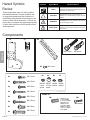
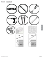
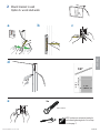
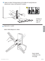
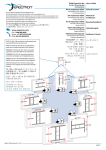
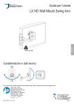
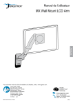
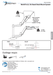
Lift30
User's Guide
OM1100604
Capacity
Lift
Rotation
VESA
27”- 42”
12 - 30 lbs
(5.5 - 13.6 kg)
≥10”
(25.4mm)
Yes
100 x 100
100 x 200
200 x 200
200 x 100
300 x 300
400 x 400
ENGLISH
Screen
Table of Contents
TV/Display Specifications. . . . . . . . . . . . . . . . . . . . . . . . . . . . . . . . . . . . . . . . . . . . . . 1
Safety Hazard Symbol Review. . . . . . . . . . . . . . . . . . . . . . . . . . . . . . . . . . . . . . . . . . 2
Components . . . . . . . . . . . . . . . . . . . . . . . . . . . . . . . . . . . . . . . . . . . . . . . . . . . . . . . . 2
Tools . . . . . . . . . . . . . . . . . . . . . . . . . . . . . . . . . . . . . . . . . . . . . . . . . . . . . . . . . . . . . . 3
Determine mounting location . . . . . . . . . . . . . . . . . . . . . . . . . . . . . . . . . . . . . . . . . . . 4
Mount Glide to wall:
Option A: wood stud walls. . . . . . . . . . . . . . . . . . . . . . . . . . . . . . . . . . . . . . . . . . . . 5
Option B: solid concrete walls. . . . . . . . . . . . . . . . . . . . . . . . . . . . . . . . . . . . . . . . . 6
Attach TV/Display to Glide . . . . . . . . . . . . . . . . . . . . . . . . . . . . . . . . . . . . . . . . . . . . . 7
Option A: no VESA adapter needed . . . . . . . . . . . . . . . . . . . . . . . . . . . . . . . . . . . . 9
Option B, C, D: with VESA adapters . . . . . . . . . . . . . . . . . . . . . . . . . . . . . . . . . . . 9
Quick Release . . . . . . . . . . . . . . . . . . . . . . . . . . . . . . . . . . . . . . . . . . . . . . . . . . . . . 12
Test Range of Motion . . . . . . . . . . . . . . . . . . . . . . . . . . . . . . . . . . . . . . . . . . . . . . . . 13
Adjust according to applied load and desired user force . . . . . . . . . . . . . . . . . . . . . 13
www.omnimount.com
User's Guide - English
Guía del usuario - Español
Manuel de l’utilisateur - Français
Gebruikersgids - Nederlands
Benutzerhandbuch - Deutsch
Guida per l’utente - Italiano
Användarhandbok - svenska
ユーザーガイド : 日本語
用户指南 : 汉语
888-61-054-W-00 rev. E • 10/13
1 of 14
Hazard Symbols
Review
Symbol
These symbols alert users of a safety condition
that demands attention. All users should be able
to recognize and understand the significance of
the following Safety Hazards if encountered on the
product or within the documentation. Children who
are not able to recognize and respond appropriately
to Safety Alerts should not use this product without
adult supervision!
Signal Word
Level of Hazard
NOTE
A NOTE indicates important information that helps you
make better use of this product.
CAUTION
A CAUTION indicates either potential damage to
hardware or loss of data and tells you how to avoid the
problem.
WARNING
A WARNING indicates either potential for property damage, personal injury, or death.
ELECTRICAL
An Electrical indicates an impending electrical hazard
which, if not avoided, may result in personal injury, fire
and/or death.
Components
1x
1x
4x
2x
M8 anchor
ENGLISH
M6 x 70mm
2x
M4 x 6mm
8x
4x
M4 x 15mm
4x
M4 x 30mm
4x
M5x 15mm
4x
M5 x 30mm
4x
M6 x 15mm
4x
4x
4x
2 of 14
M6 x 30mm
M8x 15mm
M8 x 30mm
4x
4x
4x
4x
M6-M8 M6-M8 M4-M5 M6-M8
x 5mm x 10mm washer washer
spacer spacer
M8M5 kit
4x
M8M5 Converter
Conversor M8M5
Convertisseur M8M5
M8M5-Konverter
M8M5 Convertor
Convertitore M8M5
M8M5 konverterare
M8M5サイズ変換ネジ
M8M5 转接件
4x
M5 x 20mm
888-61-054-W-00 rev. E • 10/13
Tools Needed
ENGLISH
10 mm
1/8”
3/8”
9.5-10mm
1/8”
3.2mm
888-61-054-W-00 rev. E • 10/13
3-1/8”
80mm
3/8”
3-1/8”
80mm
3 of 14
1 Determine mounting location.
CAUTION: Before proceeding with this installation consult your TV/large display product guide for
manufacturer recommendations on choosing a mounting location that will ensure optimum TV/large
display performance. Location considerations might include: TV/large display height and viewing
angle - based on height and distance of seating, room dimensions and size of TV/large display; access
to power outlets; cable connections for speakers and other devices; protection from glare and heat,
(windows, lamps, fireplace, air ducts) and vibration.
Locate the wall mount bracket on the wall using the dimensions below, as a guide.
Lift range of motion
at highest position
ENGLISH
Wall mount bracket
7.3”
(184mm)
2.5”
(66mm)
2.8”
(72mm)
Lift range of motion
at lowest position
4 of 14
888-61-054-W-00 rev. E • 10/13
2
Mount bracket to wall
Option A: wood stud walls
a
b
c
ENGLISH
d
1/8”
1/8”
3.2mm
3-1/8”
80mm
e
2x
M6 x 70mm
10mm
888-61-054-W-00 rev. E • 10/13
NOTE: make sure extension bracket is
level before tightening bolts. Go to Step
3 on the page 7.
5 of 14
Mount bracket to wall
2
a
b
c
d
ENGLISH
3/8”
3/8”
9.5-10mm
e
2x
2x
M6 x 70mm
10mm
1
WARNING:
Mounting holes must be at least 3-1/8” (80mm) deep and
must be located within solid concrete, not mortar or covering material. If you drill into an area of concrete that is
not solid, reposition mounting holes until both anchors
can be fully inserted into solid concrete!
3-1/8”
80mm
2
3
M8 anchor
WARNING:
Anchors that are not fully set in solid concrete will not support the applied load
resulting in an unstable, unsafe condition which could lead to personal injury and/or
property damage. Consult a construction professional if you have any doubt about
what this means in regard to your particular situation.
NOTE: make sure extension bracket is
level before tightening bolts. Go to Step
3 on the page 7.
6 of 14
888-61-054-W-00 rev. E • 10/13
3 Ensure the bracket is level.
a
b
4
Determine TV/large display mount fasteners
Several sizes of screws and spacers have been provided for mounting the Glide brackets to your TV/large displaychoose those that best match the depth and diameter of the mounting holes on the back of your TV/large display, along
with the design of the area surrounding the mounting holes (Flat, Curved or Inset).
ENGLISH
NOTE: If a stand is already attached to your TV/large display, remove it according to TV/large display manufacturer directions. Place the display on a clean, flat, padded surface or, if you prefer, lean the TV/large display against a
stable, vertical surface.
TV/Display Style
If your TV/large display has a curved or inset mounting hole configuration, you may need to use the provided spacers or
washers with the screws.
Hole Depth and Diameter
Four sets of display bracket screws have been provided, each of a different diameter: 4mm, 5mm, 6mm, and 8mm.
Compare the screws with the diameter of the mounting holes at the back of your TV/large display to find the same size.
NOTE: Washer A is provided for use with the 4mm and 5mm screws while Washer B works with 6mm and 8mm screws.
Test screw diameters and lengths until you find the right match to your TV/large
display.
Ø
888-61-054-W-00 rev. E • 10/13
7 of 14
5
Determine if VESA adapters are needed between TV/display and Glide LD
Check the shape and size of your TV/large display mounting hole configuration against the VESA configurations shown below. Choose VESA option that matches and continue to Step 6 on the next page.
TV/large display Mounting Hole Configurations
VESA Mounting Hole Configurations
100mm
100mm
Option A
100 x 100
400mm
300mm
400mm
300mm
Option B
200mm
ENGLISH
200mm
200 x 200
300 x 300
400 x 400
100mm
Option C
200mm
100 x 200
Option D
200mm
200 x 100
100mm
8 of 14
888-61-054-W-00 rev. E • 10/13
Option A: Attach TV/large display to the Glide LD using fasteners
determined in step 4 and spacers if needed
6mm
6mm
6mm
6
Continue to
Step 7 on
page 12.
Options B, C, and D
ENGLISH
6
Attach VESA Adapters to Glide.
Step 6 details
continued on the
next page.
888-61-054-W-00 rev. E • 10/13
9 of 14
VESA Mounting Hole
Configurations
Option B
Option C
Option D
Rotate VESA plate to access mounting holes.
a
M4 x 6mm
ENGLISH
8x
b
Step 6
continued
on the
next
page.
10 of 14
888-61-054-W-00 rev. E • 10/13
6
Options B, C, and D (cont.)
c
Attach TV/large display to the Glide LD using fasteners determined
in step 4 and spacers if needed
6mm
6mm
6mm
ENGLISH
888-61-054-W-00 rev. E • 10/13
11 of 14
Mount Lift30 (with attached TV/large display) to bracket on wall.
ENGLISH
7
Quick-release instructions: to remove from the wall, pull
down on the strap below the extension.
a
12 of 14
b
888-61-054-W-00 rev. E • 10/13
8
Adjustment Step
Important! You will need to adjust this product after installation is complete. Make sure all your equipment is
properly installed on the product before attempting adjustments. This product should move smoothly and easily
through the full range of motion and stay where you set it. If movements are too easy or difficult or if product
does not stay in desired positions, follow the adjustment instructions to create smooth and easy movements.
Depending on your product and the adjustment, it may take many turns to notice a difference. Any time
equipment is added or removed from this product, resulting in a change in the weight of the mounted load, you
should repeat these adjustment steps to ensure safe and optimum operation.
Adjust lift up and down.
Increase Lift Strength
If the mounted weight is too heavy or
this product does not stay up when
raised, then you'll need to increase
Lift Strength:
ENGLISH
Decrease Lift Strength
If the mounted weight is too light or
this product does not stay down when
lowered, then you'll need to decrease
Lift Strength:
10mm
888-61-054-W-00 rev. E • 10/13
13 of 14
Thank you for purchasing an OmniMount product
ENGLISH
NEED HELP? PLEASE CALL
OmniMount, Inc.
4409 East Baseline Road, Suite 130,
Phoenix, AZ 85042
1-800-MOUNT-IT (1-800-668-6848)
www.omnimount.com
All trademarks are the property of their respective companies. OmniMount is a registered trademark of OmniMount, Inc. © 2012
Disclaimer – OmniMount, Inc. has extended every effort to ensure to accuracy and completeness of this manual. However, OmniMount, Inc. does not claim that the information covers all installation
or operational variables. The information contained in this document is subject to change without notice or obligation of any kind. Regarding the information contained herein, OmniMount, Inc.
makes no representation of warranty, expressed or implied, and assumes no responsibility for accuracy, sufficiency, or completeness of the information contained in this document.
Wall Mounts
WARNING: FAILURE TO READ, THOROUGHLY UNDERSTAND, AND FOLLOW ALL INSTRUCTIONS CAN RESULT IN SERIOUS PERSONAL INJURY, DAMAGE TO PERSONAL PROPERTY, OR VOIDING OF FACTORY WARRANTY!
It is the responsibility of the installer to ensure all components are properly assembled and installed using the instructions provided. If you do not understand these instructions or have any questions
or concerns, please contact customer service at 1-800-668-6848 or [email protected].
Do not attempt to install or assemble this product if the product or hardware is damaged or missing. In the event that replacement parts or hardware are needed, please contact Customer Service at
1-800-668-6848 or [email protected]. International customers needing assistance should contact the Dealer from which they purchased the product.
14 of 14
888-61-054-W-00 rev. E • 10/13