1
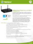
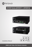
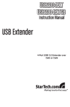
4 Port USB 2.0 Extender over Gigabit
Ethernet or Cat5e/6 Cabling - 100m (330ft)
USB2G4LEXT2
*actual product may vary from photos
DE: Bedienungsanleitung - de.startech.com
FR: Guide de l'utilisateur - fr.startech.com
ES: Guía del usuario - es.startech.com
IT: Guida per l'uso - it.startech.com
NL: Gebruiksaanwijzing - nl.startech.com
PT: Guia do usuário - pt.startech.com
For the most up-to-date information, please visit: www.startech.com
Manual Revision: 02/06/2014
FCC Compliance Statement
This equipment has been tested and found to comply with the limits for a Class B digital
device, pursuant to part 15 of the FCC Rules. These limits are designed to provide reasonable
protection against harmful interference in a residential installation. This equipment generates,
uses and can radiate radio frequency energy and, if not installed and used in accordance with
the instructions, may cause harmful interference to radio communications. However, there
is no guarantee that interference will not occur in a particular installation. If this equipment
does cause harmful interference to radio or television reception, which can be determined by
turning the equipment off and on, the user is encouraged to try to correct the interference by
one or more of the following measures:
• Reorient or relocate the receiving antenna.
• Increase the separation between the equipment and receiver.
• Connect the equipment into an outlet on a circuit different from that to which the receiver
is connected.
• Consult the dealer or an experienced radio/TV technician for help.
Use of Trademarks, Registered Trademarks, and other Protected Names and Symbols
This manual may make reference to trademarks, registered trademarks, and other
protected names and/or symbols of third-party companies not related in any way to
StarTech.com. Where they occur these references are for illustrative purposes only and do not
represent an endorsement of a product or service by StarTech.com, or an endorsement of the
product(s) to which this manual applies by the third-party company in question. Regardless
of any direct acknowledgement elsewhere in the body of this document, StarTech.com hereby
acknowledges that all trademarks, registered trademarks, service marks, and other protected
names and/or symbols contained in this manual and related documents are the property of
their respective holders.
Instruction Manual
Table of Contents
Introduction.............................................................................................1
Packaging Contents.................................................................................................................................. 1
System Requirements............................................................................................................................... 1
Product Overview...................................................................................2
The Local Extender.................................................................................................................................... 2
The Remote Extender............................................................................................................................... 3
Installation...............................................................................................4
Network Connect....................................................................................................................................... 4
Direct Connect............................................................................................................................................ 7
Verifying Installation..............................................................................10
Pairing and Unpairing............................................................................11
Pairing the Local and Remote Extender............................................................................................ 11
Unpairing an Extender............................................................................................................................. 11
Compatibility...........................................................................................12
Troubleshooting......................................................................................12
Specifications...........................................................................................15
Technical Support...................................................................................16
Warranty Information.............................................................................16
Instruction Manual
i
Introduction
Packaging Contents
• 1 x USB 2.0 Extender Local Unit
• 1 x USB 2.0 Extender Remote Unit
• 1 x USB A-B Cable
• 1 x Universal Power Adapter (NA/ UK/ EU)
• 1 x Mounting Kit
• 1 x Instruction Manual
System Requirements
• Windows® 8 (32/64bit), 7 (32/64), Vista (32/64), XP (32/64), 2000, Windows® Server
2012, 2008 R2, 2003 (32/64), Windows CE 6.0, Mac OS 10.x (Tested up to 10.9), Linux®
• USB-enabled computer system with an available USB port
• Available AC power outlet
• Cat5e/6 Ethernet Cable(s)
• Preconfigured Local Area Network (for network connect setup)
Instruction Manual
1
Product Overview
The Local Extender
The Local Extender connects to the computer using a standard USB 2.0 cable. Power
for this unit is provided by the host computer.
Front View
Rear View
Item
Type
1
Power LED
(Blue)
LED turns on when power is supplied, off when no power is supplied by the
host computer.
2
Link LED
(Green)
Indicates a valid USB link is established between the Local and Remote
units. The LED turns on when a link between Local and Remote Extender is
established and turns off when there is no link. Fast blinking indicates the
unit is in “Pairing Mode” while slow blinking indicates the unit is attempting
to establish a link.
3
Host LED
(Green)
Indicates that the extender is properly connected to the host computer. The
LED blinks when the extender is in a suspended state.
4
Activity LED
(Amber)
Indicates data transmission is occurring between the Local and Remote
units. The LED blinks intermittently with or without a USB device connected.
When the Local and Remote Extender are in suspend mode the LED is off.
5
Pair
Used to establish a paired connection between Local and Remote Extenders.
6
USB Host Port
7
Link Port
(RJ45)
8
Config
Instruction Manual
Description
Used to connect the Local Extender to the host computer. Accepts a USB
Type B connector into the Local Extender.
Accepts a RJ45 connector for Cat 5e (or better) cabling to connect the Local
Extender to the Remote Extender.
Reserved.
2
The Remote Extender
The Remote Extender provides USB Type A ports for standard USB devices, and allows
you to connect up to four USB devices directly. Additional devices may be connected
by attaching USB hubs to the Remote Extender. The Remote Extender is powered by an
external AC adapter and can supply up to 600ma to each USB port.
Front View
Rear View
Item
Type
1
USB Device
Ports
Description
Accepts USB device(s) using Type A connectors.
2
Power LED
(Blue)
LED turns on when power is supplied, off when no power is supplied.
3
Link LED
(Green)
Indicates a valid USB link is established between the Local and Remote
units. The LED turns on when a link between Local and Remote Extender is
established and turns off when there is no link. Fast blinking indicates the
unit is in “Pairing Mode” while slow blinking indicates the unit is attempting
to establish a link.
4
Host LED
(Green)
Indicates that the extender is properly connected to the host computer. The
LED blinks when the extender is in a suspended state.
5
Activity LED
(Amber)
Indicates data transmission is occurring between the Local and Remote
units. The LED blinks intermittently with or without a USB device connected.
When the Local and Remote Extender are in suspend mode the LED is off.
6
Power Port
Connects to the AC power supply. Required at the Remote Extender for
proper operation.
7
Pair
Used to establish a paired connection between Local and Remote Extenders.
8
Link Port
(RJ45)
Accepts a RJ45 connector for Cat 5e (or better) cabling to connect the Local
Extender to the Remote Extender.
9
Config
Instruction Manual
Reserved.
3
Installation
Note: Units will be pre-paired with each other out of the box. If they are not paired,
follow the instructions provided in the section for Pairing a Local and Remote Extender.
Network Connect
Installing the USB2G4LEXT2 on a Local Area Network
Requirements
To complete the installation, you will also require the following items that are not
included with the product:
• USB compatible computer (host computer) with a USB compliant operating system
• USB compatible device(s)
• Two Cat 5e (or better) Ethernet cables
• Preconfigured Local Area Network
Cat 5e Cable
USB Cable
USB cable or device
connectors
Preparing Your Network
Your network must be properly configured to achieve USB 2.0 throughput and
for maximum stability and reliability of your devices. Consult with your network
administrator prior to installation. Using the USB2G4LEXT2 over a network requires:
• Local Extender and Remote Extender to be on the same subnet
• Pre-installed and configured Local Area Network
Instruction Manual
4
Note: Some networks may be configured to block devices with unfamiliar MAC
addresses. If this is the case, you will need to provide your network administrator the
MAC addresses of the Local and Remote Extender units. These can be found on the
label on the bottom of each unit.
Preparing Your Site
Before you can install the USB2G4LEXT2, you need to prepare your site:
1. Place the computer where desired and set it up.
2. Ensure that where you want to locate the USB device(s) is within 100m (330ft) of the
switch.
3. Ensure that where you want to locate the computer is within 100m (330ft) of the
switch.
Note: The cable distance between switches must be no greater than 100m (330ft).
Installing the Local Extender
1. Place the Local Extender near the computer.
2. Connect the provided USB cable between the Local Extender host port and a
USB port on the host computer.
3. Connect a Cat 5e (or better) cable (not provided) into to a network switch or wall
network port connected to a switch.
4. Connect the opposite end of the Ethernet cable into the Link port of the
Local Extender
Instruction Manual
5
Installing the Remote Extender
1. Connect a Cat 5e (or better) cable (not provided) into a network switch or wall
network port connected to a switch.
2. Connect the opposite end of the Ethernet cable into the Link port of the Remote
Extender
3. Place the Remote Extender near the USB device(s).
4. Connect the provided power adapter to an available AC power outlet, and to the
Power port of the Remote Extender.
5. Attach your USB device(s) to the Remote Extender.
Instruction Manual
6
Direct Connect
Installing the USB2G4LEXT2 as Direct Connect
Requirements
To complete the installation, you will also require the following items that are not
included with the product:
• USB compatible computer (host computer) with a USB compliant operating system
• USB compatible device(s)
• One or Two Cat 5e (or better) cables
Preparing Your Site
Before you can install the USB2G4LEXT2, you need to prepare your site:
1. Place the computer where desired and set it up.
2. Ensure that where you want to locate the USB device(s) is within 100m (300ft) of the
computer. If not, adjust the location of the devices and/or computer accordingly.
Installing the Local Extender
1. Place the Local Extender near the computer.
2. Connect the provided USB cable between the Local Extender’s host port and a USB
port on the host computer.
Instruction Manual
7
Connecting the Local Extender to the Remote Extender
With Surface Cabling
1. Connect the Cat 5e or better cable into the Link port of the Local Extender.
2. Connect the Cat 5e or better cable into the Link port of the Remote Extender.
Instruction Manual
8
With Wall Network Ports
1. Connect a Cat 5e or better cable (not provided) into the RJ45 wall outlet near the
host computer.
2. Connect the opposite end of the cable into the Link port of the Local Extender.
3. Connect a Cat 5e or better cable (not provided) into the RJ45 wall outlet near the
USB devices.
4. Connect the opposite end of the cable into the Link port of the Remote Extender.
Installing the Remote Extender
1. Place the Remote Extender near the USB device(s).
2. Connect the provided power adapter to an available AC power outlet, and to the
Power port of the Remote Extender.
3. Attach your USB device(s) to the Remote Extender.
Instruction Manual
9
Verifying Installation
1. On the Local and Remote Extender, check that the Power, Status, Link and Host LEDs
are on.
Note: For direct connect, if the Host or Link LEDs are permanently off, then the
cabling between the Local and Remote Extender may not be installed properly or is
defective.
For network connect, if the Link LED is blinking, then the network connection
between the Local and Remote Extender is not complete and there may be faulty
cabling, network components, misconfigured network components, or the Local
and Remote Extender may need to be re-paired together (see the section on pairing
a Local and Remote Extender).
2. Windows: Open the Device Manager by right-clicking on Computer, and then
select Manage. In the new Computer Management window, select Device Manager
from the left window panel (For Windows 8, open the Control Panel and select
Device Manager).
Expand the entry for Universal Serial Bus controllers by clicking the “+” sign. If the
USB2G4LEXT2 has been installed correctly you should find it listed as a “Generic
USB Hub”.
Instruction Manual
10
3. Mac OS: Open the System Profiler to confirm that the USB2G4LEXT2 has installed
correctly. In the left hand column under Hardware, select “USB” and inspect the right
hand panel. If the extender has been installed correctly, you should find it listed as a
“Hub” under the USB High-Speed Bus/USB Bus.
To open System Profiler in OS X: Open the Finder, select Applications, then open the
Utilities folder and double click on the System Profiler icon.
Pairing and Unpairing
Pairing the Local and Remote Extender
The extenders will be paired with each other out of the box, so no pairing action
should be required. However, if you wish to change the Local and Remote Extender
pairings across a network, then the following steps must be taken:
1. Ensure the Local and Remote Extender are directly connected to each other, or are
connected to the same subnet on your network.
2. Press and hold the Pairing button on the back of the Local Extender. Release the
button within 10 seconds. The Link LED will start flashing.
3. Within 10 minutes of activating the pairing mode on the Local Extender, press and
hold the Pairing button on the back of the Remote Extender. Release the button
within 10 seconds. The Link LED will start flashing.
4. The Link LED on both units may start flashing more slowly before finally turning on.
Once the Link LEDs are solid, the link is established between both extenders.
Note: If more than 10 minutes pass before the units are paired, then the extenders
will switch back to regular mode and reestablish the previous links they had, if any. To
cancel pairing mode, press and hold the Pairing button a second time. Release it within
10 seconds.
Unpairing an Extender
If for any reason an extender needs to have its pairing removed, this can be done
by pressing and holding the Pair button for longer than 10 seconds. Once this is
completed the unit will not be paired to any other extender.
Instruction Manual
11
Compatibility
The USB2G4LEXT2 complies with USB 1.1 and USB 2.0 specifications. However, there is
no guarantee that all USB devices or hosts will be compatible with the USB2G4LEXT2,
as there are a number of different characteristics that may impact the operation of USB
devices over extended distances.
Troubleshooting
The following table provides troubleshooting tips. The topics are arranged in the order
in which they should be executed in most situations.
Problem
Cause
Solution
All LEDs on
the Local
Extender are
off.
• The Local Extender
is not receiving
power from the
USB port.
1. Ensure that the host computer is
connected to the Local Extender.
All LEDs on
the Remote
Extender are
off.
• The Remote
Extender is not
receiving power
from the AC adapter.
Link LEDs on
the Local and
the Remote
Extenders are
off.
Instruction Manual
• There is no
connection between
the Local and
Remote Extenders.
2. Move the USB connector to another
USB port on the host computer.
1. Ensure that the AC power adapter is
properly connected to the Remote
Extender.
2. Check that the AC adapter is
connected to a live source of electrical
power. Check that the Remote power
LED is illuminated.
1. Ensure Cat 5e cable is connected
between the Local and Remote
Extenders. Cat 5e or better cable, UTP
with a straight through connector and
no crossovers, and 8 conductor RJ45
connectors are used at both ends.
2. Connect a short Cat 5e patch cord
between the Local and Remote
Extenders to determine if the original
Cat 5e cable is defective.
12
1. Ensure both the Local and Remote
Extenders are connected together
directly or are connected to active
network switches.
• There is no
connection between
the Local and
Remote Extenders.
Link LEDs are
blinking.
2. Re-pair the units together.
• Units may not be
paired to each other.
3. Ensure the network switches can
communicate with each other and are
on the same subnet.
• Network switches
exist on different
subnets.
4. Ensure the network switches are not
blocking traffic from the extenders
either based on MAC address or due
to traffic patterns.
• Network switch(es)
are blocking traffic
from the extenders.
Link LED on
the Local and
the Remote
Extenders
are blinking
slowly.
Link LED on
the Local
Extender is
on, Host LED
on the Local
Extender is off.
5. Consult with your network
administrator.
1. Wait for a few minutes for the LEDs to
go solid.
• The extenders are
paired with each
other but have not
yet established
a link.
2. If LEDs do not go solid, contact your
network administrator to determine if
any traffic is being blocked between
the extenders.
• The host computer
is not powered on.
1. Disconnect all USB devices from the
Remote Extender.
• The Local Extender
is not connected to
the computer.
2. Disconnect the Local Extender from
the computer.
3. Disconnect the Remote Extender from
the AC power adapter.
• The host computer
is not recognizing
the Local. Extender.
4. Reconnect the Local Extender to the
computer.
5. Reconnect the Remote Extender to
the AC power adapter.
• The computer does
not support USB
hubs.
6. In the Universal Serial Bus controllers
section of Device Manager, check that
the RG2304GE-LAN is recognized as a
“Generic USB Hub”.
• The RG2304GE-LAN
is malfunctioning.
Instruction Manual
13
My USB device
does not work
properly.
My USB device
does not work
at all.
Instruction Manual
• Insufficient
bandwidth is
available on the
network to support
the device.
1. Connect the Local and Remote
Extenders directly to each other and
try the USB device again.
• Insufficient
bandwidth is
available on the
network to support
the device.
1. Connect the Local and Remote
extenders directly to each other and
try the USB device again.
2. Follow the instructions on page 11
and pair the Local to the Remote
Extender that is connected to the
device you wish to use.
• The Local Extender
is paired to the
wrong Remote
Extender.
14
Specifications
Cabling
Cat 5e UTP or better
Ports
4
1 x RJ-45 Female
Local Unit Connectors
1 x USB B (4 pin) Female
1 x RJ-45 Female
Remote Unit Connectors
4 x USB A (4 pin) Female
Maximum Cable Length
330 ft [100 m]
1 Gbps (LAN)
Maximum Data Transfer Rate
480 Mbps (USB)
Enclosure Material
Steel
Dimensions (LxWxH)
100 x 76 x 26 mm
Weight
LEDs
12.8 oz (363 g)
Local Extender – 4 (Power, Link, Host,
Activity)
Remote Extender – 4 (Power, Link, Host
Activity)
Power Adapter
24V, 1A DC
Operating Temperature
0°C to 50°C (32°F to 122°F)
Storage Temperature
-10°C to 60°C (14°F to 140°F)
Humidity
20-80% RH
Compatible Operating Systems
Windows® 8 (32/64bit), 7 (32/64), Vista
(32/64), XP (32/64), 2000, Windows® Server
2012, 2008 R2, 2003 (32/64), Windows
CE 6.0, Mac OS 10.6 and up (Tested up to
10.9), Linux®
Instruction Manual
15
Technical Support
StarTech.com’s lifetime technical support is an integral part of our commitment to
provide industry-leading solutions. If you ever need help with your product, visit
www.startech.com/support and access our comprehensive selection of online tools,
documentation, and downloads.
For the latest drivers/software, please visit www.startech.com/downloads
Warranty Information
This product is backed by a two year warranty.
In addition, StarTech.com warrants its products against defects in materials
and workmanship for the periods noted, following the initial date of purchase.
During this period, the products may be returned for repair, or replacement with
equivalent products at our discretion. The warranty covers parts and labor costs only.
StarTech.com does not warrant its products from defects or damages arising from
misuse, abuse, alteration, or normal wear and tear.
Limitation of Liability
In no event shall the liability of StarTech.com Ltd. and StarTech.com USA LLP (or their
officers, directors, employees or agents) for any damages (whether direct or indirect,
special, punitive, incidental, consequential, or otherwise), loss of profits, loss of business,
or any pecuniary loss, arising out of or related to the use of the product exceed the
actual price paid for the product. Some states do not allow the exclusion or limitation
of incidental or consequential damages. If such laws apply, the limitations or exclusions
contained in this statement may not apply to you.
Instruction Manual
16
Hard-to-find made easy. At StarTech.com, that isn’t a slogan. It’s a promise.
StarTech.com is your one-stop source for every connectivity part you need. From
the latest technology to legacy products — and all the parts that bridge the old and
new — we can help you find the parts that connect your solutions.
We make it easy to locate the parts, and we quickly deliver them wherever they need
to go. Just talk to one of our tech advisors or visit our website. You’ll be connected to
the products you need in no time.
Visit www.startech.com for complete information on all StarTech.com products and
to access exclusive resources and time-saving tools.
StarTech.com is an ISO 9001 Registered manufacturer of connectivity and technology
parts. StarTech.com was founded in 1985 and has operations in the United States,
Canada, the United Kingdom and Taiwan servicing a worldwide market.