1
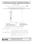
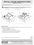
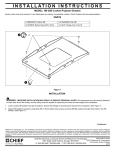
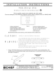
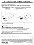
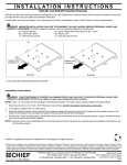
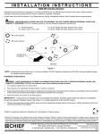
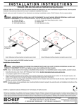
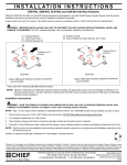
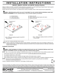
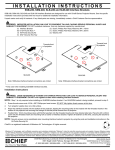
INSTALLATION
INSTRUCTIONS
PSB-2264
DISPLAY MOUNTING BRACKET
Prior to assembly, unpack carton completely and verify contents.
If you are missing any of the following components, please contact Customer Service at 1-800/582-6480
Figure 1
(2) Interface Brackets
(4) 10-24 x .500 Button Head Cap Screws
(4) Nylon Spacer .740” x .390” x 1.00”
(1) 1/8” Allen Key
(4) Mounting Buttons – Tapped
(4) M10 x 50mm Hex Head Cap Screw
(4) Nylon Spacer 22mm x 10.4mm x 20mm
(1) Wrench, Hex 17mm
BEFORE PROCEEDING, READ INSTALLATION INSTRUCTIONS COMPLETELY
CAUTION!
WARNING!
DISPLAYS ARE EXTREMELY FRAGILE.
ALL COMPONENTS MUST BE SECURELY FASTENED TO A
STRUCTURAL MEMBER CAPABLE OF SUPPORTING 4
TIMES THE COMBINED WEIGHT OF ALL COMPONENTS
PLUS THE EQUIPMENT BEING MOUNTED. IF IT CANNOT
SUPPORT THIS WEIGHT, THE STRUCTURE MUST BE
REINFORCED.
THE MAXIMUM WEIGHT TO BE INSTALLED ON THE
MOUNT IS 175 POUNDS (79.38 KG).
1. Chief Q-latch Button Installation
Using a 10-24 button head cap screw inserted from back side of bracket, secure mounting button, with
chamfered hole of mounting button (larger surface) facing bracket (four places) (see Figure 2 & Figure3).
Figure 2
Chief Manufacturing, a division of Milestone AV Technologies
8401 Eagle Creek Parkway, Savage, MN 55378
P: 800.582.6480 / 952.894.6280 F: 877.894.6918 / 952.894.6918
Figure 3
8804-000368
©2008 Milestone AV Technologies,
A Duchossois Group Company
11/08
2. Bracket Installation: Attach interface to back of the display using the M10 Hex Head Bolts and nylons spacers.
Use the set of spacer that provide the best depth for your display. (see Figure 4 & Figure
5). Do not over tighten screws.
Figure 4
Figure 5
3. Follow the Chief mount instruction manual for screen installation.