1
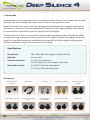
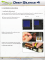
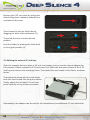
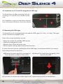
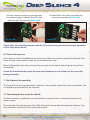
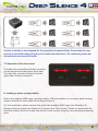
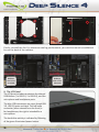
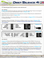
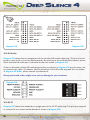
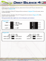
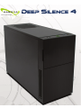
EN
I. Introduction________________________________________________________________02
• Specifications __________________________________________________________02
________________________________________________________________02
• Accessories
• Features ________________________________________________________________03
_________________________________________________________06
II. Installation Instructions
___________________________________________________06
1. Installation of the motherboard
______________________________________________________07
2. Installation of the power
supply
3. Installation of external drives________________________________________________07
___________________________________________________07
3.1 Optical drives
______________________________________08
3.2 Utilizing the external 3.5 inch bay
_________________________________________09
4. Installation options of HDD’s
_______________________________________________09
4.1 Mounting of hard disk drives
4.2 Installation of a 2.5 inch SSD alongside the HDD______________________________10
cages
___________________________________________10
4.3 Removing the HDD-cages
_______________________________________________11
5. Removing the front panel
______________________________________________11
6. Fan assembly
_______________________________________________11
6.1 Front fans
6.2 Fans under the top cover _______________________________________________12
7. The 2-channel fan control ________________________________________________12
________________________________12
7.1 Connecting the fans to the fan control
7.2 Operation of the fan control _____________________________________________13
8. Installation of a water cooling _______________________________________________13
solution
9. The I/O-Panel ___________________________________________________________14
10. Connecting the front connectors to the motherboard ___________________________15
10.1 USB 2.0 ____________________________________________________________15
10.2 USB 3.0 ___________________________________________________________15
10.3 HD Audio __________________________________________________________16
10.4 AC 97 ______________________________________________________________16
III. Support
_____________________________________________________________18
01
I. Introduction
Congratulations on the purchase of your new Nanoxia Deep Silence 4 mini tower. We are confident that you will be delighted by your new PC case for many years to come.
Nanoxia’s Deep Silence series have been designed and developed by an experienced team of
developers in Germany. The silent optimized PC cases are of the highest quality and combine
the best possible functionality with the highest level of flexibility.
The Deep Silence 4 Tower is a particularly compact housing that provides nevertheless sufficient space for high-end graphics cards and current CPU coolers. Due to the modular hard drive
cages, the case offers maximum versatility and compatibility, both for water cooling project
and the installation of high-end systems with air cooling.
Specifications
Dimensions:
Material:
External drive bays:
Internal drive bays:
380 x 200 x 480 mm (Height x Width x Depth)
0.6 mm steel
1 x 5.25 inch (tool-free)
1x 5.25 inch /w 3.5 inch adapter (tool-free)
6 x 3.5/2.5 inch bays (decoupled),
1 x 2.5 inch SSD mounting holes
Accessories
Rubber sealings for
tube holes
EPS extension
Fan screws
Stand-offs for mainboard
Screws for mainboard
mounting
Screws for HDD mounting
Screws for 3.5” mounting
frame
Mounting screws for
2.5“HDD/SSD
Mounting screws for PSU
Thumbscrews
02
EN
If you are missing any of the items listed above, please contact our customer service
immediately:
[email protected] (Germany and Europe);
[email protected] (international)
Features:
- Watercooling ready
- Complete customizable soundproofing with high quality materials meeting industrial
standards
- Tool-free mounting of optical drives
- 2 x USB 3.0, 1 x USB 2.0
- 4 Slots for expansion cards
- Max. VGA length: 265 mm (up to 395 mm with the HDD cages removed)
- Room for CPU coolers with a maximum height of up to 160 mm
- Mounting hole for CPU cooler in the motherboard tray
- Cable management with 3 rubberised holes in the motherboard tray
- Stepless 2-channel fan control
- Nanoxia VentCover (noise indulated): 1 x top cover
Noise Insulation
The Nanoxia Deep Silence 4 has been developed with the aim to offer the buyer a low-noise
case, while at the same time allowing for extremely low system temperatures. The sound insulation design of the Deep Silence 4 is based on multiple interacting design elements:
The most important part is the large scale lining of the case with sound-absorbing insulation
materials. These materials are manufactured specifically to meet the requirements of the
developers of the Nanoxia Deep Silence case series. The insulation consists of a bitumen fabric
layer and a foam compound that acts equally against airborne sound, while the bitumen fabric
layer specifically reduces the vibrational characteristics of the case.
Included are special rubber seals which can be used to alternatively close the tube holes above
the rear chassis fan, in case you don’t need to use them.
The removable Nanoxia VentCover masks the 120/140 mm fan hole in the case top. It allows
the user to choose between the least possible noise and improved case ventilation.
03
Another design element for optimum sound insulation is the use a sound-insulated front door.
The door is equipped with sound-absorbing foam.
The hard disk drives are installed on trays which feature rubber grommets that are designed
to absorb any vibrations caused by the HDDs. The power supply is isolated from the case by a
flexible rubber framework and also rests on rubber contact points on the bottom of the PSU.
The whole concept of sound proofing of the Deep Silence 4 meets the highest expectations.
Ventilation System
The Deep Silence Nanoxia 4 has an integrated ventilation system consisting of two 120 mm
Deep Silence fans and a built-in 2-channel fan controller. A total of up to three fans can be
mounted.
The Nanoxia VentCover under the top can be removed at any time and allows the installation
of a 120 mm or 140 mm fan for optimized heat dissipation.
The Deep Silence axial flow fans have been specifically optimised for very quiet operation. The
range of fan speeds and controls was designed to enable each user to adjust the case ventilation to their own needs.
All air intake openings (front and bottom) are readily accessible and have easy to clean dust filters. Behind the front cover, an “Easy Access Panel” is located, allowing an easy access to both
the dust filter and the front 120 mm fan.
Standard Equipment:
Front:
Rear:
1 x 120 mm Nanoxia Deep Silence fan (max. 1,300 rpm)
1 x 120 mm Nanoxia Deep Silence fan (max. 1,300 rpm)
Optional Equipment:
Top cover:
Bottom:
04
2 x 120/140 mm
1 x 120/140 mm fans (removal of HDD-holder necessary)
EN
Watercooling-ready
The Nanoxia Deep Silence 4 like any other Nanoxia case has been prepared for the installation
of a water cooling system.
Therefore you can install radiators or a compact water cooling solution behind the front cover.
Front: 120 mm radiator
Behind the front panel, a 120 mm radiator can be mounted. Please note that the upper two
HDD-cages must be removed for this.
If you want to mount a compact water cooling system behind the front, you should check
before the installation, whether the factory hoses between cooler and radiator are of sufficient
length.
Rubber hose guides:
The Deep Silence 4 offers two rubber hose guides, so that the appropriate water cooling components can be operated or mounted externally.
On the next pages you can find some useful tips and explanations for the optimal use of your
new case and for the installation of your hardware.
05
II. Installation Instructions
1. Installing the Motherboard
You can mount M-ATX and Mini-ITX motherboards in the Deep Silence 4. In order to ensure an
easy installation of your motherboard, we suggest the following procedure:
a) Please consult the following charts to
find your motherboard form factor:
b) Attach the stand-offs according to your
motherboard form factor.
c) Attach the included EPS extension cable
on to your motherboard – do not connect it
to the power supply yet.
06
Micro-ATX
Mini-ITX
EN
d) Next you should mount the CPU cooler - for very large CPU coolers, the attachment of the
EPS extension cable after installation can be difficult.
e) Now place the motherboard gently inside
the case and lead the EPS extension cable
through the opening provided in the top left
of the mainboard tray.
f) Fix the motherboard to the motherboard tray.
g) After the installation of the power supply, you can connect the EPS extension cable to the
EPS-connector on the PSU at the back of the motherboard-tray.
2. Installation of the power supply
Please install the power supply according
to the diagram below and secure it with
the included PSU screws.
The dust filter at the bottom can
be pulled out for easy cleaning.
3. Installation of external drives
You can install up to two external drives in the Deep Silence 4. An adapter frame for mounting
a 3.5 inch drive is included.
3.1 Optical drives
To install the optical drives, please remove both side panels. The installation of optical drives is
tool-free.
07
Remove the 5.25 inch cover by pulling the
lateral tilting lever cautiously towards you
and take out the cover.
Then loosen the lock on both sides by
dragging the black slider backwards (1).
1
Then slide the drive into the desired
position.
Lock the holder by pushing the slider back
to its original position (2).
2
3.2 Utilizing the external 3.5 inch bay
If you for example desire to place a 3.5 inch card reader, you can use the internal adaptor for
this purpose. Please remove the 5.25 inch cover first. Open the two quick release of the 5.25
inch bay and remove the mounting frame. Then attach the card reader in the frame, as shown
below.
Then place the frame with the card reader
back into the slot and lock the quick release.
Finally, attach the included 3.5 inch front
panel carefully on top of the card reader.
Alternatively, the adaptor can be used for the installation of an additional 3.5 inch hard drive.
08
EN
4. Installation options for hard drives
The Deep Silence 4 allows you the decoupled mounting of six hard disk drives in the partly
modular HDD-cages.
4.1 Mounting of hard drives
Install the 2.5 or 3.5 inch hard drives in the illustrated mounting frames. In order to extract the
frame, squeeze the protruding brackets and pull the slide out gently.
To install a hard drive into a bracket insert the disk so that the connectors point to the back and
attach the hard drive using the screws provided.
For the fitting of 3.5 inch hard drives
please use the holes in Figure 4A
Abb. 4A
For the fitting of 2.5 inch hard drives
please use the holes in Figure 4B
Abb. 4B
To lock the drive, push the bracket with the
drive back installed back into the slot until
the bracket is re-engaged.
09
4.2 Installation of a 2.5 inch SSD alongside the HDD cage
The Deep Silence 4 offers mounting holes for
installing a 2.5 inch SSD at the bottom of the
case.
For installation, simply put the disk on the bottom of the case and secure it from the outside.
4.3 Removing the HDD-cages
The Deep Silence 4 is equipped with two modular HDD-cages (1 x 3-bay, 1 x 2-bay). The cages
can be removed or swapped at will.
Due to this unique variability, you can:
- Adjust the number of available HDD mounts
- Install extra-long graphic cards
- Optimize the air flow within the case
- Mount a water cooling system behind the front fans
In order to ensure an easy modification of the HDD-cages, we recommend that you remove
both side panels of the case first.
a) Remove the upper age (A) by pressing the
lever upwards, as shown in the picture.
a) Now pull the hard drive cage gently in the
opposite direction.
A
c) If you want to remove the middle cage as well, repeat steps a) and b) as stated above.
10
B
EN
If you want to remove the middle cage and use only the upper cage, please note that the
upper cage (A) is not firmly anchored to the case. It can be pulled out of the case without
effort, if the central cage (B) is not installed.
The bottom HDD cage for a single 2.5 / 3.5 inch HDD/SSD is not removable.
5. Removing the front panel
To remove the front panel, simply hold the
cut-out at the bottom of the front panel and
pull it towards you with a firm tug.
Please note that the cables from the I/O
panel are guided through the upper part of
the front into the chassis. Please be careful
when you remove the front.
6. Fan assembly
Two 120 mm fans are pre-installed in your Deep Silence 4. You can mount up to three fans in
total.
You can, of course, connect the additional fans to the fan controller (see Chapter 7).
The fan in the front is equipped with an easy to clean dust filter. We recommend that you
clean it on a regular basis.
6.1 Front Fans
To switch the fan in the front or to clean
the dust filters, first remove the front panel
(see chapter 5). Next, open the “Easy Access
Panel” by pushing slightly on the left side of
the panel (picture 6A).
picture 6A
11
You can remove the fan by pushing away
the retaining lugs a little bit from the fan
and then pull the fan out (picture 6B).
picture 6B
The dust filter can easily be pulled out,
as you can see here (picture 6C).
picture 6C
Please note, that the filter element must be fully inserted to guarantee the proper operation
of the “Easy Access Panel”.
6.2 Fans in the top cover
If you want to install an additional fan at the top of the case, please remove the Nanoxia VentCover first by removing the screws on the outside of the case.
Next, hold the fans from the inside and secure them to the top by fastening the screws from
the outside.
A case fan installed at the top of the case should exhaust air out of the case (fan rear side
facing outwards).
7. The 2-channel fan controller
The Deep Silence 4 is equipped with a stepless 2-channel fan control for up to six case fans. You
can operate up to three fans per channel.
7.1 Connecting the fans to the fan control
The fan controller is powered by a 4-pin Molex connector that is connected directly to the
power supply.
The controller has two channels (A and B), with each channel able to control up to three 3-pin
fans, therefore a total of six fans can be controlled.
12
EN
The fan controller is not designed for the operation of powerful fans. Please take this into
account in particular when using fans from other manufacturers. The maximum power per
channel must not exceed 18 watts.
7.2 Operation of the fan control
The sliders for controlling the fans controller
can be found behind the upper front door.
The left slider controls channel A and the
right slider controls channel B.
8. Installing a water cooling solution
Due to the modular HDD cages, you can install a 120 mm radiator or a compact water cooling
solution behind the front panel of the Deep Silence 4.
For the installation, please remove the upper two modular HDD-cages (see Chapter 4.2).
Remove the front panel (see Chapter 5) and open the “Easy Access” Panels to remove the fan.
Hold the radiator from the inside and secure it with screws, using the corresponding mounting
slots.
13
Finally, reinstall the fan. For maximum cooling performance, you can also mount an additional
fan on the back of the radiator.
Radiator
with 1 fan
mounted
9. The I/O-Panel
The I/O panel includes connectors for external
USB devices (1 x USB 2.0, 2 x USB 3.0), and the
microphone and headphone ports.
The blue USB connectors are super-Speed USB
3.0, USB 2.0 ports are black. The left audio
connector (when viewed from the front) is
for headphones, the right is intended for a
microphone.
The hard drive activity is indicated by flickering
of the green illuminated power button.
14
Radiator
with 2 fans
mounted
EN
10. Connecting the front connectors to the motherboard
10.1 USB 2.0
Diagram 10A shows the standard pin assignment of the USB cable plug. The pins are assigned
in a way to fit on current motherboards as shown in diagram 10B.
Please refer to the motherboard and check that the internal USB port of your motherboard is
identical to the one shown in diagram 10A.
If the pin allocation of the internal USB port is the one shown in diagram 10A it is then possible
to connect the cable.
If, however, the pin allocation of the internal USB port and the one shown in diagram 10A
differ, please consult a professional. Wrong connected cables might cause serious damage to
your hardware.
Diagram 10A
Diagram 10B
10.2 USB 3.0
Diagram 10C shows the typical pin assignment of the internal 19-Pin USB 3.0. The pins are
assigned in a way to fit on current motherboards (diagram 10D). By referring to the motherboard manual, please check that the internal 19-pin USB 3.0 port is identical to the one shown
in diagram 10C.
If the pin allocation of the internal 19-Pin USB 3.0 plug and the one shown in diagram 10C are
the same, please connect the cable. If, however, the pin allocation of the internal 19-Pin USB
3.0 plug and the one shown in diagram 10C differ, please consult a professional. Wrong connected cables might cause serious damage to your hardware.
If your motherboard does not have an internal USB 3.0 port, you can acquire an internal 19-pin
to external 2x USB 3.0 Type A adapter cable.
15
Diagram 10C
Diagram 10D
10.3 HD Audio
Diagram 10E shows the pin assignment of the standard HD audio cable plug. The pins are assigned in a way to fit on current motherboards. By referring to the motherboard manual, please
check that the HD audio port is identical to the one shown in diagram 10E.
If the pin allocation of the HD audio plug and the one shown in diagram 10E are the same, please connect the cable. If, however, the pin allocation of the HD audio plug and the one shown
in diagram 10E differ, please consult a professional.
Wrong connected cables might cause serious damage to your hardware.
Diagram 10E
10.4 AC 97
Diagram 10F shows the standard pin assignment of the AC 97 cable plug. The pins are assigned
in a way to fit on current motherboards as shown in diagram 10G.
16
EN
Referring to your motherboard manual, please check if that the AC 97 port is identical to the
typical shown in diagram 10G.
If the pin allocation of the AC 97 plug and the one shown in diagram 10G are the same, please
connect the cable.
If, however, the pin allocation of the AC 97 plug and the one shown in diagram 10G differ,
please consult a professional.
Wrong connected cables might cause serious damage to your hardware.
Diagram 10F
Diagram 10G
17
III. Support
Dear customer,
The PC case you purchased has undergone a very thorough quality control. Nevertheless,
should there be any unexpected problems with your case we ask that you first approach the
dealer where you purchased the product. They are prepared to assist you with competent and
uncomplicated advice and practical support.
If perhaps a few screws were missing or you might have a question that can’t be answered by
this manual, please do not hesitate to contact us directly by e-mail.
Likewise, we would appreciate your suggestions and comments about our case very much. Our
staff will respond to all inquiries quickly and professionally.
Customers from Germany and other European countries can use the following e-mail address
for support questions, spare parts or warranty issues:
[email protected]
Customers from Africa, Asia, Australia as well as North and South America can use the following e-mail address for support questions, spare parts or warranty issues:
[email protected]
For general inquiries, comments, suggestions and the like please refer to:
[email protected]
We are sure that you will be satisfied with Nanoxia Deep Silence 4 for many years to come, so
please enjoy your new PC case.
Your Nanoxia Support-Team
36
Copyright © 2013 Nanoxia UG