1
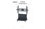
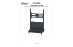
PFT8857
Installation Guide
Installationsanleitung, Guía de Instalacíon, Guida de Installazione, Guide d’Installation, Installatie gids
www.vogels.com
9531-060-Z05-00
PFT8857
Installation Guide
Installationsanleitung, Guía de Instalacíon, Guida de Installazione, Guide d’Installation, Installatie gids
Included components
x2
M6 x 12mm
M8 x 10mm
x4
M16 x 35mm
x4
M8 x 60mm
x2
x4
M5 x 6mm
x1
14mm
x20
M8
x1
x1
5/32”
x4
x4
M8 x 60mm
x20
M8
x4
M6 x 10mm
2.5mm
M4
x4
x4
M4
M8
x1
5mm
Required for installation
If this is a “one man” installation find a “friendly” clear flat
wall to place one leg assembly along side. Place the lower
pan panel on top of the legs channel between the “upright”.
Next place the second leg over the lower pan panel so all
four through holes line up and loosely secure the lower pan
to the legs with the four M8 x 1.25 x 60mm “button head Allen head screws and M8 flat washers supplied.
1
3
Laying the paired leg assembly first on its back and then on
its front securely install the four casters on the front and rear
of the leg assemblies using the M8 flat washers and M8 self
locking nuts supplied. Then securely install the four casters.
We recommend the two rear caster be the “locking pair”
2
1
5mm
9531-060-Z05-00
2
4x
4x
3x
13mm
www.vogels.com
16x
16x
PFT8857
Installation Guide
Installationsanleitung, Guía de Instalacíon, Guida de Installazione, Guide d’Installation, Installatie gids
Loosely install the front upper cover to the front of the cart
with the four M6 x 1.0 x 10mm”button head” Allen screws
supplied.
1
3
3
4x
4mm
Install the front “logo” plate to the lower panel cover with the
four each 10/32 x 1/2” “kep” nuts and flat washers supplied.
Repeat the same procedure with the upper rear panel to the
leg assembly with the four each “button head” Allen screws
supplied.
Now secure firmly the four lower pan “button head” screws
to the leg assembly and tighten firmly. Repeat the same process with the front and rear upper cover panels but “don’t”
over-tighten these.
2
4
4mm
6
4
3
5
6
13mm
9531-060-Z05-00
5mm
www.vogels.com
4
4x
The rear oval panel cover can be installed before or after
final assembly of the cart with the four each M6 button head
Allen head screws supplied.
PFT8857
Installation Guide
Installationsanleitung, Guía de Instalacíon, Guida de Installazione, Guide d’Installation, Installatie gids
Install the lower front panel cover to the frame front and
secure to the frame assembly with the four each M6 x 1.0 x
10mm “button head” Allen head screws supplied
1
7
4x
4mm
Two people recommended for this portion of the “mega” cart
assembly process. Raise the receiver cross bar assembly
to the desired “centerline” height and secure to the uprights
firmly with the four “button head Allen screws and flat washers supplied.
With the rear of the lower pan exposed now would be the
time to place and wire any powered support products feeding the display with the power and signal cable being fed
between the front and rear upper cover panels. Power and
signal cable can also be run up through the three rubber
grommet hole in the base ob the pan as well.
Once housed the rear cover panel may now be installed
with the four “button head” Allen screws supplied. Access to
the inner pan is still available through the rear oval access
cover.
2
8
3
9
5mm
9531-060-Z05-00
4mm
10
4
4x
4x
www.vogels.com
4x
The 90 degree rotation stop can be installed to allow for left
or right rotation of the arm only. Simply remove the two M6
flat head screw to reposition the 90 degree stop plate and
reinstall
PFT8857
Installation Guide
Installationsanleitung, Guía de Instalacíon, Guida de Installazione, Guide d’Installation, Installatie gids
With the display safely positioned “face down” on a smooth
flat surface place the cross bar with brackets loosely attached so the center of the round receiver is center on the
display left to right and top to bottom.
Slide the left and right mounting bracket over the left and
right mounting holes (normally four each) and firmly install
the brackets to the display with the correct length M8 x 1.25
Phillips head screw supplied. Note: measure the depth of
the threaded mounting hole to confirm the correct length of
the M8 screws from the three lengths supplied Confirm the
crossbar is still centered left to right on the rear of the display and firmly secure the bracket to the cross bar with the
four M6 x 1.0 x 10mm Allen head set screws supplied.
Eight optional use M4 - M8 plastic spacer are included in
the hardware kit if needed to create clearance between the
mounting g bracket and the display. These
spacers easily joined together for additional height is
needed as well.
11
1
12
2
13
3
13
4
5/32”
9531-060-Z05-00
5/32”
www.vogels.com
Slide the left and right display mounting brackets over the
cross bar and install the left and right M6 x 1.0 x 12mm security Phillips head screws supplied into the cross bar.
CL
PFT8857
Installation Guide
Installationsanleitung, Guía de Instalacíon, Guida de Installazione, Guide d’Installation, Installatie gids
Remove the M6 security holding screw from the receiver and
set to the side for re-install after the crossbar and display
are installed into the received slots.
14
1
15
2
Depending on the size and weight of the display use appropriate number or personal and lift assistance device to
raise and slowly install the round center of the cross bar into
the round receiver chassis and insure it is fully seated in the
receiver chassis.
Re-install the M6 security screw.
16
3
17
4
Friction of the rotation can be adjusted by increasing or
decreasing the friction screw on either side of the receiver
assembly penetration of the two installed friction screw with
a Phillips head screwdriver.
9531-060-Z05-00
www.vogels.com
PFT8857
Installation Guide
Installationsanleitung, Guía de Instalacíon, Guida de Installazione, Guide d’Installation, Installatie gids
Vertical flatness of the installed display can be adjusted using an M10 socket and ratchet on the lower “head assembly.
IT helps if someone is gently lifting “out” on the lower display
as the “tilt in” adjustment is made.
18
1
19
2
M10
9531-060-Z05-00
M2.5
www.vogels.com
With the 2.5mm Allen head wrench supplied install the two
each M5 x 6mm mini adjustment Allen head screws supplied
to both sides of the “rotation” stop bar. slowly turn the display to the level position in each direction and adjust the two
adjust screw to set max rotation in each direction to level.
PFT8857
Installation Guide
Installationsanleitung, Guía de Instalacíon, Guida de Installazione, Guide d’Installation, Installatie gids
8
7
14
ITEM NO. QTY.
3
9
10
1
11
PART NO.
REV
DESCRIPTION
3201-000-010-XX
02
VERTICAL LEFT LEG ASSEMBLY 2X2
1
3201-000-020-XX
02
2
0725-DCG-W02-13
4
4
0411-079-320-6X
SCREW BUTTON HEX (M8 x 1.25 x 60)
5
20
198X-507-600-50
WASHER M8 ( .335 ID ) X ( .621 OD ) X ( .063 THK )
6
20
0398-061-091-6X
7
1
3201-000-001-XX
8
3
1558-BUD-P00-86
9
1
3201-000-005-XX
00
ACCESS PANEL
10
1
3201-000-060-XX
02
REAR PANNEL WELDED ASSY
02
1
1
2
3
VERTICAL RIGHT LEG ASSEMBLY 2X2
PLUG PUSH-IN RIBBED SQUARE CAP 2 X 2"
SCREW BUTTON HEX (M6 x 1.0 x 10)
03
LOWER TRAY
GROMMET BUNA-N RUBBER (1.50I.D) X (2.13 OD) X (.5"THK)
11
1
3201-000-006-XX
12
4
198X-265-100-35
SIGN PANEL
13
4
1200-034-007-5X
14
2
3201-000-015-XX
01
UPPER COVER
15
1
3201-000-003-XX
05
FRONT COVER
16
16
1070-079-015-0X
N/A
17
2
0031-000-001-07
18
2
0031-000-001-08
19
1
3201-000-008-XX
WASHER M4 ( .172 ID ) X ( .347 OD ) X ( .031 THK )
NUT KEP (6/32"X .109)
NUT LOCK NYLON INSERT M8X1.25 X 8
DURABLE SUPERIOR CASTERS (SWIVEL)
DURABLE SUPERIOR CASTER (LOCKING)
00
SIGN PANEL BACKING PLATE
5
15
2
13
12
17
16
4
18
6
13
8
1
3
ITEM NO. QTY.
3
5
4
2
7
ITEM NO. QTY. PART NO.
REV
1
4 0411-079-320-6X
2
4 201X-50A-B00-55
3
1 3201-000-070-XX 02
4
1 3106-000-035-XX 02
5
4 1658-079-091-6X
6
2 1658-052-061-6X
7
2 6095-PSD-E-E
00
8
2 0474-061-104-6X
9
2 3106-000-038-XX 01
8
DESCRIPTION
SCREW BUTTON HEX (M8 x 1.25 x 60)
WASHER LG O.D M8 (.335 ID) X (.934 O.D) X (.079)
85"- 103" FLAT PANEL ROLLING CART BACK PLATE
SWIVEL TUBE ASSEMBLY (LARGE)
SET SCREW CUP POINT ( M8 X 1.25 X 10 )
SET SCREW CUP POINT ( M5 X 0.8 X 6 )
PLASTIC CAP (ELLIPTICAL TUBE 3.149 X 1.574 )
SCREW PAN PHILLIPS COMB (M6X1.0 X 12)
MOUNTING BRACKET ASSEMBLY XLARGE (ELLIPTICAL)
2
11
9
5
9531-060-Z05-00
www.vogels.com
1
0477-061-320-9X
2
1
3106-000-019-XX
02
HEX FULLY THREADED M6x1.0x60
3
1
3106-000-018-XX
03
ROTAIONAL MOUNT BRACKET
4
1
6441-10-RUM-RFC
01
RUM FRONT COVER
5
4
0422-061-182-6X
SCREW FLAT 90 DEGREES PHILLIPS (M6 x 1.0 x 25)
6
2
0474-079-153-6X
SCREW PAN PHILLIPS COMB (M8X1.25 X 20)
7
4
198X-507-600-50
8
2
1070-079-015-0X
FRONT COVER ( ROTATION BEARING)
WASHER M8 ( .335 ID ) X ( .621 OD ) X ( .063 THK )
N/A NUT LOCK NYLON INSERT M8X1.25 X 8
9
2
0474-061-153-6X
SCREW PAN PHILLIPS COMB (M6X1.0 X 20)
1
199X-447-700-50
1/4" WASHER SAE (.286 ID) X (.630 OD) X (.065 THK)
11
1
198X-396-200-50
WASHER M6 ( .256 ID ) X ( .464 OD ) X ( .060 THK )
12
1
1070-061-012-9X
13
1
3201-000-080-XX
02
85"- 103" FLAT PANEL ROLLING CART BACK PLATE
7
14
1
3106-000-024-XX
00
ROTATIONAL STOP
6
15
2
0422-061-104-6X
16
1
180X-063-117-70
17
1
3106-000-040-XX
18
2
2303-657-601-60
19
1
0562-061-077-6X
9
12
REV DESCRIPTION
1
10
6
4
PART NO.
1
18
NYLON INSERT HEX LOCK NUT (M6x1.0x.236) DIN 985
SCREW FLAT 90 DEGREES PHILLIPS (M6 x 1.0 x 12)
SPACER NYLON 6/6 (.250 ID) X (.555 OD) X (.551 THK)
00
1/2" TILT ROD WELDED ASSY
FLG BUSH.BRONZE,SAE 863 (.500 ID X .625 O.D X .375 LG X .8
00
SCREW KNURL KNOB PHILLIPS (M6X1.0 X 8)