1
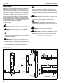
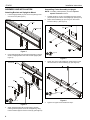
INSTALLATION INSTRUCTIONS
Center Channel Speaker Accessory
Spanish Product Description
German Product Description
Portuguese Product Description
Italian Product Description
Dutch Product Description
French Product Description
FCA530
FCA530
Installation Instructions
DISCLAIMER
Milestone AV Technologies and its affiliated corporations and
subsidiaries (collectively "Milestone"), intend to make this
manual accurate and complete. However, Milestone makes no
claim that the information contained herein covers all details,
conditions or variations, nor does it provide for every possible
contingency in connection with the installation or use of this
product. The information contained in this document is subject
to change without notice or obligation of any kind. Milestone
makes no representation of warranty, expressed or implied,
regarding the information contained herein. Milestone assumes
no responsibility for accuracy, completeness or sufficiency of
the information contained in this document.
WARNING: Exceeding the weight capacity can result in
Chief® is a registered trademark of Milestone AV Technologies.
All rights reserved.
WARNING: Never operate this mounting system if it is
serious personal injury or damage to equipment! It is the
installer’s responsibility to make sure the combined weight of
all components placed on the FCA530 does not exceed 20 lbs
(9.1 kg).
WARNING: Use this mounting system only for its intended
use as described in these instructions. Do not use
attachments not recommended by the manufacturer.
damaged. Return the mounting system to a service center for
examination and repair.
IMPORTANT SAFETY INSTRUCTIONS
WARNING: Do not use this product outdoors.
WARNING: A WARNING alerts you to the possibility of
serious injury or death if you do not follow the instructions.
CAUTION: A CAUTION alerts you to the possibility of
WARNING: RISK OF INJURY TO PERSONS! Do not use
this mounting system to support video equipment such as
televisions or computer monitors.
damage or destruction of equipment if you do not follow the
corresponding instructions.
--SAVE THESE INSTRUCTIONS--
WARNING: Failure to read, thoroughly understand, and
follow all instructions can result in serious personal injury,
damage to equipment, or voiding of factory warranty! It is the
installer’s responsibility to make sure all components are
properly assembled and installed using the instructions
provided.
DIMENSIONS
L
OF MOUNT
L
OF MOUNT
16.75
425.5
MAX. SPEAKER
MOUNTING PATTERN
CL
OF SPEAKER
BRACKET
CL
OF SPEAKER
BRACKET
2
DIMENSIONS:
INCHES
[MILLIMETERS]
Installation Instructions
FCA530
LEGEND
Tighten Fastener
Open-Ended Wrench
Apretar elemento de fijación
Llave de boca
Befestigungsteil festziehen
Gabelschlüssel
Apertar fixador
Chave de bocas
Serrare il fissaggio
Chiave a punte aperte
Bevestiging vastdraaien
Steeksleutel
Serrez les fixations
Clé à fourche
Loosen Fastener
Phillips Screwdriver
Aflojar elemento de fijación
Destornillador Phillips
Befestigungsteil lösen
Kreuzschlitzschraubendreher
Desapertar fixador
Chave de fendas Phillips
Allentare il fissaggio
Cacciavite a stella
Bevestiging losdraaien
Kruiskopschroevendraaier
Desserrez les fixations
Tournevis à pointe cruciforme
TOOLS REQUIRED FOR INSTALLATION
3/8"
#2
PARTS
C (1)
[Hanging bracket]
B (1)
[Shelf upright]
A (1)
[Center assembly]
D (1)
[Retaining bracket]
E (1)
[Center channel hook]
F (1)
[Center channel hook]
G (4)
10-24 x 1/2"
H (4)
10-24 x 3/8"
J (4)
1/4-20 x 1/2"
K (4)
10-24
L (4)
1/4"
M (4)
#10
3
FCA530
Installation Instructions
ASSEMBLY AND INSTALLATION
Assembling Center Assembly to Upright
Attaching Bracket and Upright to Mount
NOTE: If installing a taller speaker, proceed to Optional
1.
Lower hanging bracket (C) onto mount rail, placing hooks
over mount rail. (See Figure 1)
Speaker Installations section.
1.
Partially install two 10-24 x 3/8" Phillips pan head screws
(H) into the top two holes on shelf upright (B). (See Figure 3)
2.
Raise center assembly (A) up to hang it on two screws
inserted in Step 1. (See Figure 3)
(C)
(B)
Mount rail
2 (A)
Figure 1
2.
1
Hang shelf upright (B) onto the hanging bracket (C), placing
studs on hanging bracket into slots on shelf upright. (See
Figure 2)
(H) x 2
Figure 3
3.
Mount rail
Fasten two 10-24 x 3/8" Phillips pan head screws (H) into
the lower holes of center assembly (A). (See Figure 4)
(C)
Slots
(D)
(A)
2
(M) x 4
Studs
3
3
Figure 4
(K) x 4
4.
Figure 2
3.
4
(H) x 2
Attach retaining bracket (D) to shelf upright, pressing
retaining bracket against mount rail and tightening, using
four #10 washers (M) and 10-24 lock nuts (K). (See Figure 2)
Tighten two upper screws inserted in Step 1.
Installation Instructions
FCA530
Adjustments
1.
Loosen two nuts on each side of retaining bracket. (See
Figure 5)
2.
Adjust height of center assembly, as necessary.
3.
Tighten four nuts on retaining bracket.
1
Example of
speaker
Minimum extension
3
(E)
Longer hooks
on bottom
(L) x 2
(J) x 2
1
Maximum extension
2
(F)
2
(J) x 2
(L) x 2
Figure 6
3.
(Mount rail not shown for clarity)
Figure 5
Installing Speakers
WARNING: Exceeding the weight capacity can result in
serious personal injury or damage to equipment! It is the
installer’s responsibility to make sure the combined weight of
speakers located on the FCA530 does not exceed 20 lbs
(9.1 kg).
Attach speaker with attached center channel hooks (E, F) to
the center assembly (A) by hanging the top hook on top of
assembly, and swinging bottom of speaker in towards
center assembly. (See Figure 7)
NOTE: If speaker is too tall and hits center assembly (A) when
attempting to attach to assembly, remove center
assembly (A) from upright and proceed to Step 3 of
Installing Tall Speakers section.
(side view)
Speaker
(A)
WARNING: USING SCREWS OF IMPROPER SIZE MAY
DAMAGE THE SPEAKER. Properly sized screws will easily
and completely thread into speaker mounting holes.
NOTE: If the screws provided with this accessory do not fit the
specific speaker being installed, be sure to use
correctly sized screws (not included).
1.
Attach one center channel hook (E) to back of speaker (left
side) using two 1/4-20 x 1/2" Phillips pan head screws (J)
with two 1/4" washers (L). (See Figure 6)
NOTE: Ensure that longer hooks are at bottom of speaker.
(See Figure 6)
2.
(E or F)
Repeat with other end of speaker and the remaining center
channel hook (F). (See Figure 6)
Figure 7
5
FCA530
Installation Instructions
OPTIONAL SPEAKER INSTALLATIONS
Speaker With Teardrop Opening At Attachment
Points
1.
Example of
speaker
Insert two 10-24 x 1/2" Phillips pan head screws (G) into
center channel hooks and hang speaker on screws. (See
Figure 8)
(E)
Longer hooks
on bottom
(L) x 2
1
(J) x 2
(F)
1
2
(G) x 2
(J) x 2
(L) x 2
Figure 9
Figure 8
3.
Hang speaker with center channel hooks onto center
assembly (A).
4.
Partially install two 10-24 x 3/8" Phillips pan head screws (H)
into the top two holes on shelf upright (B). (See Figure 10)
5.
Raise center assembly (A) up to hang it on two screws
inserted in Step 1. (See Figure 10)
Installing Tall Speakers
WARNING: USING SCREWS OF IMPROPER SIZE MAY
DAMAGE THE SPEAKER. Properly sized screws will easily
and completely thread into speaker mounting holes.
NOTE: If the screws provided with this accessory do not fit the
specific speaker being installed, be sure to use
correctly sized screws (not included).
1.
(B)
Attach one center channel hook (E) to back of speaker (left
side) using two 1/4-20 x 1/2" Phillips pan head screws (J)
with two 1/4" washers (L). (See Figure 9)
NOTE: Ensure that longer hooks are at bottom of speaker.
(See Figure 9)
2.
Repeat with other end of speaker and the remaining center
channel hook (F). (See Figure 9)
5 (A)
4
(H) x 2
(speaker not shown for clarity)
Figure 10
6
Installation Instructions
6.
FCA530
Fasten two 10-24 x 3/8" Phillips pan head screws (H) into
the lower holes of center assembly (A). (See Figure 11)
(A)
6
(H) x 2
(speaker not shown for clarity)
Figure 11
7.
Tighten two upper screws inserted in Step 1.
7
FCA530
Installation Instructions
USA/International
Europe
Chief Manufacturing, a products division
of Milestone AV Technologies
8800-002268 Rev01
2012 Milestone AV Technologies,
a Duchossois Group Company
www.chiefmfg.com
11/12
Asia Pacific
A
P
F
A
P
F
A
6436 City West Parkway, Eden Prairie, MN 55344
800.582.6480 / 952.225.6000
877.894.6918 / 952.894.6918
Franklinstraat 14, 6003 DK Weert, Netherlands
+31 (0) 495 580 852
+31 (0) 495 580 845
Office No. 1 on 12/F, Shatin Galleria
18-24 Shan Mei Street
Fotan, Shatin, Hong Kong
P 852 2145 4099
F 852 2145 4477