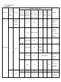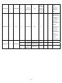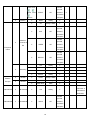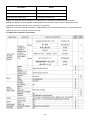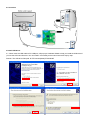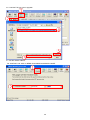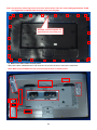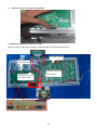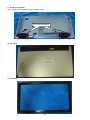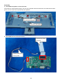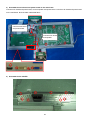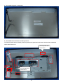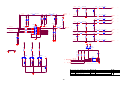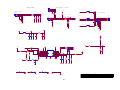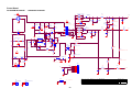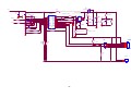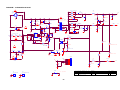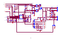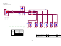
1
Applicable Country & Regions: Global Service Manual for BenQ: G2450HM: D-SUB + HDMI + DVI + AUDIO P/N: 9H.L7NLA.TBW GL2450HM: D-SUB + HDMI + DVI + AUDIO P/N: 9H.L7CLA.TBE GL2450HE: D-SUB + HDMI + DVI + AUDIO P/N: 9H.L7CLA.FBE Glossy Black Chassis Colors Product Service Manual – Level 1~2 Version: 2nd Date:10-31-2012 Notice: For RO to input specific “Legal Requirement” in specific NS regarding to responsibility and liability statements. Please check BenQ’s eSupport web site, http://esupport.benq.com, to ensure that you have the most recent version of this manual. First Edition (Sep. 2011) © Copyright BenQ Corporation 2011. All Right Reserved. 1 Content Index Abbreviations & Acronyms ........................................................................................................................................3 1. About this Manual ...................................................................................................................................................5 1.1 Important ............................................................................................................................................................5 1.2 Trademark ..........................................................................................................................................................5 2. Introduction .............................................................................................................................................................6 2.1 RoHS (2002/95/EC) Requirements – Applied to all countries require RoHS. ....................................................6 2.2 Safety Warning and Notice .................................................................................................................................6 2.3 Compliance Statement .......................................................................................................................................7 3. General Description ................................................................................................................................................8 4. Related service information...................................................................................................................................8 5. Product Overview ...................................................................................................................................................9 5.1 Monitor Specifications ........................................................................................................................................9 5.2 Panel Inspection Specification..........................................................................................................................21 Level 1 Cosmetic / Appearance / Alignment Service ............................................................................................26 Visual Inspection & Cleaning ..................................................................................................................................26 F/W Upgrade SOP..................................................................................................................................................26 Adjustment / Alignment Procedure .........................................................................................................................43 Level 2 Circuit Board and Standard Parts Replacement ......................................................................................58 Product Exploded View ..........................................................................................................................................58 Six Angles’ View .....................................................................................................................................................60 Product Disassembly/Assembly .............................................................................................................................61 Block Diagram ........................................................................................................................................................71 Schematic Diagram ................................................................................................................................................74 Troubleshooting ......................................................................................................................................................85 PCB LAYOUT .............................................................................................................................................................91 Appendix 1 – Screw List / Torque ...........................................................................................................................99 2 Abbreviations & Acronyms A ADC Analog to Digital Converter AFC Automatic Frequency Control: control signal used to tune to the correct frequency B BenQ BenQ Corporation BTSC Broadcast Television System Committee C CPU CVBS Central Process Unit Composite Video Blanking and Synchronization D DLP Digital Light Processing / Texas Instruments® DMD Digital Micro mirror Device DRAM DVI Dynamic RAM Digital Visual Interface DVI-D Digital Visual Interface-digital DVI-I Digital Visual Interface-Integrated E EEPROM Electrically Erasable and Programmable Read Only Memory F FLASH FLASH memory G G-TXT Green Teletext H HDMI HP High Definition Multimedia Interface, digital audio and video interface Head Phone I I2C Integrated IC bus L LED LVDS Light Emitting Diode Low Voltage Differential Signal, data transmission system for high M MOSFET Metal Oxide Semiconductor Field Effect Transistor N 3 NC NVM Not Connected Non Volatile Memory: IC containing TV related data (for example, options) O OSD On Screen Display P PC PCB Personal Computer Printed Circuit Board (or PWB) R RC RGB ROM Remote Control transmitter Red, Green and Blue. The primary color signals for TV. By mixing levels of R, G and B, all colors (Y/C) are Read Only Memory S SDA SDRAM SW Data signal on I2C bus Synchronous DRAM Sub Woofer / Software T THD Total Harmonic Distortion V VGA Video Graphics Array Y YPbPr Y/C Component video (Y= Luminance, Pb / Pr= Color difference signals B-Y and R-Y, other amplitudes w.r.t. to YUV) Video related signals: Y consists of luminance signal, blanking level and sync; C consists of color signal. 4 1. About this Manual The purpose of Service Manual is to provide a guide line to engineers to repair different models. The appearance and capability is introduced in this Service Manual. It is better for repair engineer to have a rough idea of this model through reading the Service Manual. Please do pay attention to the item part of the disassembly when repair the machine and also do the protection of panel any time. When repairing the circuit board, please follow the requirement of RoHS and refer to the circuit diagram and repairing process that attached in the Service Manual. The method of firmware updated, the way of using the menu and some information that may be used when repairing are also attached in the Service Manual that provide repair engineer various choice. 1.1 Important Only trained service personnel who are familiar with this BenQ Product shall perform service or maintenance to it. Before performing any maintenance or service, the engineer MUST read the “Important Safety Information”. 1.2 Trademark 5 2. Introduction This section contains general service information, please read through carefully. It should be stored for easy access place. 2.1 RoHS (2002/95/EC) Requirements – Applied to all countries require RoHS. The RoHS (Restriction of Hazardous Substance in Electrical and Electronic Equipment Directive) is a legal requirement by EU (European Union) for the global electronics industry which sold in EU and some counties also require this requirement. Any electrical and electronics products launched in the market after June 2006 should meet this RoHS requirements. Products launched in the market before June 2006 are not required to compliant with RoHS parts. If the original parts are not RoHS complaints, the replacement parts can be non ROHS complaints, but if the original parts are RoHS compliant, the replacement parts MUST be RoHS complaints. If the product service or maintenance require replacing any parts, please confirming the RoHS requirement before replace them. 2.2 Safety Warning and Notice Installation 1. Do not use your monitor under any of the following environmental conditions: Extremely high or low temperature, or in direct sunlight Dusty places Highly humid, exposed to rain, or close to water Exposed to vibrations or impacts in places such as cars, buses, trains, and other rail vehicles Near heating appliances such as radiators, heaters, fuel stoves, and other heat-generating items (including audio amplifiers) An enclosed place (such as a closet or bookcase) without appropriate ventilation An uneven or sloping surface Exposed to chemical substances or smoke 2. Do not block vents and openings by clothes or curtains. 3. Carry the monitor carefully. 4. Do not place the monitor face down on the floor or a desk surface directly. Otherwise, scratches on the panel surface may occur. 5. Do not place heavy loads on the monitor to avoid possible personal injury or damage to the monitor. 6. Ensure that children do not hang or climb onto the monitor. 7. Keep all packing bags out of reach of children. 6 Operation 1. To protect your eyesight, please refer to the user manual to set the optimal screen resolution and the viewing distance. 2. To reduce eye fatigue, take a break on a regular basis while using the monitor. Avoid taking either one of the following actions for a long time. Otherwise, burn marks may occur. Use the monitor in the aspect ratio of 16:9. Place a still image (such as an OSD menu, fixed text or image) on the screen. 3. To avoid possible damage to the monitor, do not touch the monitor panel by hand, pen, or any other sharp objects. 4. Excessively frequent plug and unplug of video connectors (D-sub / DVI) may cause damage to the monitor. 5. This monitor is designed mainly for personal use. If you want to use the monitor in a public place or a harsh environment, contact your nearest BenQ service center for assistance. 6. To avoid possible electric shock, do not dissemble or repair the monitor. 7. If a bad smell or an abnormal sound appears to come from the monitor, contact your nearest BenQ service center for assistance immediately. Cleaning 1. Ensure that the power is unplugged before cleaning your monitor 2. Use a monitor cleaner and a soft cloth to clean your monitor. 3. Do not use solvents such as alcohol to clean your monitor. Power 1. To avoid possible damage to the monitor, do not use it in a region where power supply is unstable. 2. Ensure that the power cord is connected to a grounded power outlet before turning on the monitor. 3. Use only the power cord provided by BenQ. 4. Never use a power cord that appears to be damaged or frayed. 5. To avoid possible danger, observe the total electric load when using the monitor with a (multi-outlet) extension cord. 6. Always turn off the monitor before unplugging the power cord. 2.3 Compliance Statement Caution: This Optical Storage Product contains a Laser device. Refer to the product specifications and your local Laser Safety Compliance Requirements. 7 3. General Description This new LCD (Liquid Crystal Display) monitor BenQ G2450HM&GL2450HM/GL2450HE offers numerous features and functions, for example: Panel Type: TN + CCFL (For G2450HM) Panel Type: TN + LED (For GL2450HM/GL2450HE) Minimal space requirements thanks to slim casing Optimum ergonomic characteristics (totally distortion-free, excellent picture definition and color purity right into the corners) Contrast ratio 50000:1 (DCR), brightness 300nits (For G2450HM) Contrast ratio 12 million:1 (DCR), brightness 250nits (For GL2450HM/GL2450HE) MAX. resolution (1920X1080) Presentation of up to 16.7 M colors (in conjunction with an appropriate graphics card) Automatic scanning of horizontal frequencies from 30 to 83 kHz and refresh rates (vertical frequencies) from 50 to 76 Hz (absolutely flicker-free) Digital screen controller with microprocessor for storing 15 different display modes Freely adjustable color alignment for matching the screen colors to the colors of various input and output devices Convenient operation via integrated OSD (On-Screen-Display) menu VESA-DDC compatibility Plug & play capability Power management for reducing power consumption when the computer is not in use This operating manual contains important information you require to start up and run your LCD monitor. This specification defines the requirements for the 24″ MICROPROCESSOR based Multi-mode supported high resolution color LCD monitor. This monitor can be directly connected to general 15-pin VGA connector and 24-pin DVI-D connector, also supports VESA DPMS power management and plug & play function. Additional information Due to the nature of liquid crystal display (LCD) technology, the picture resolution is always fixed. For the best display performance, please set the display resolution to 1920X1080 pixels with an aspect ratio of 16:9. This is called “Native Resolution” or maximal resolution - that is, the clearest picture. Lower resolutions are displayed on a full screen through an interpolation circuit. Image blurring across pixel boundaries can occur with the interpolated resolution depending upon the image type and its initial resolution. 4. Related service information This Service Manual contains general information. There are 2 levels of service: Level 1: Cosmetic / Appearance / Alignment Service Level 2: Circuit Board or Standard Parts Replacement Service Web Site eSupport URL: http://esupport.benq.com 8 5. Product Overview 5.1 Monitor Specifications G2450HM GL2450HM/GL2450HE Conf. 2 Conf. 3 D-sub (include component source) + D-sub (include component source) + DVI-D + HDMI + speaker DVI-D + HDMI + speaker TN + CCFL TN + LED Panel Size 24"W(16:9) 24"W(16:9) Display Area 531.36x298.89 531.36x298.89 Max. Resolution 1920X1080 1920X1080 Pixel Pitch 0.276 0.276 Brightness (Typ.) 300 cd/m2 250 cd/m2 1000:1(Panel)/50000:1 (DCR) 1000:1(Panel)/12M:1 (DCR) 170/160 170/160 Display Colors 16.7M 16.7M Response Time 5ms (Tr+Tf) 5ms (Tr+Tf) GtG response Time 2ms 2ms MPRT N/A N/A NTSC ratio 72% 70~72% Senseye 3 Senseye 3 6 Modes (by hotkey) : Standard / 6 Modes (by hotkey) : Standard / Panel Type (TN / VA / IPS) Panel / Display Contrast Ratio (Typ.) / DCR (Min.) Viewing Angle (H/V), CR≥10 BenQ SenseyeTM Technology BenQ SenseyeTM Video Preset Modes Movie / Game / Photo / s-RGB / ECO Movie / Game / Photo / s-RGB / ECO Color Temperature Normal (6500°K) / Reddish (5800°K) / Normal (6500°K) / Reddish (5800°K) / Selection Bluish (9300°K) / User Mode Bluish (9300°K) / User Mode AMA (Over Drive ) Yes Yes Hor. Frequency (kHz) 30-83 30-83 Ver. Frequency (Hz) 50-76 50-76 205 205 Video Bandwidth (MHz) Audio Speakers (built-in) 2W x 2 2W x 2 Input/Output PC Video Input D-sub/DVI-D/HDMI D-sub/DVI-D/HDMI 9 Power Supply Audio line in Yes Yes Earphone Jack Yes Yes Voltage Rating AC: 100~240V (Built-in) AC: 100~240V (Built-in) Power-On Mode <35W (max) <35W (max) Standby Mode <0.3W (max) <0.3W (max) Power Off Mode <0.3W (max) <0.3W (max) Glossy black, detail refer to artwork Glossy black, detail refer to artwork Chassis Colors (proposal A) Carton Brown Carton with at least C flute (BE Brown Carton with at least C flute (BE flute CTN for BQjp shipments) flute CTN for BQjp shipments) Power LED Green (ON)/ Amber (Standby) Green (ON)/ Amber (Standby) Tilt (Up / Down) 15° ~ -5° 15° ~ -5° VESA Wall Mount 100 x 100 mm 100 x 100 mm Kensington Lock Yes Yes >1300 >1300 >650 >650 17 Languages (English / Francais / 17 Languages (English / Francais / Deutsch / Italiano / Espanol / Polish / Deutsch / Italiano / Espanol / Polish / Czech / Hungarian / Serbo-croatian / Czech / Hungarian / Serbo-croatian / Romanian / Netherlands / Russian / Romanian / Netherlands / Russian / Swedish / Portuguese / Japanese / Swedish / Portuguese / Japanese / Chinese / S-Chinese) Chinese / S-Chinese) Vista Premium Premium Win 7 Yes Yes Yes Yes Accessories Refer to SKU list Refer to SKU list Regulation Refer to the worksheet Refer to the worksheet Approvals "RFQ-Regulatory" "RFQ-Regulatory" Mechanical Design Container Loading (foam cushion 40') Container Loading (foam cushion 20') Multi-language Support Other feature OSD Dynamic Power Saving (DPS) 10 5.1.1 Certification G2450HM Certification / Requirement Shipment Region Country (Pls Country select) Request for Certification Regulatory (Black is Type Certification mandatory (safety/safety (Pls select) and blue is & Applied by vendor Applied BenQ by Sample Remark BenQ Reguest voluntary) EMC/EMC/GP) Must include Australia, V New radiation test V C-Tick EMC V result for Zealand frequency above 1GHz Including CCC certificate, V CCC Safety & EMC CCC report V and CCC label printing permission Eff(Minimun) Level = 1 Energy Label GP V 2 Vender provide Asia-Pacific V China V China RoHS GP relevant information and report Recycling V China WEEE GP notice in User See Remark Manual is required. One sample of DVT is V CECP GP V 1 set. required for the assigned third-party test. V V Japan VCCI EMI V PSE DOC for V PSE Safety V HDMI sku base on CB 11 and VCCI Vender provide V J-Moss GP relevant information and report If VOC Class Level: ★ ★★ PC3R GP ★★★ Vender test is provide requested, relevant V please information provide 1 and report sample for Meet the PC3R requirement of 2009 version. testing. V KCC EMC V KC Safety & EMC V Vender V V e-Standby GP Korea provide One sample of relevant DVT information and formal test report (Korean) Vender provide V Korea RoHS GP relevant information and report V Singapore V PSB Safety 12 V V 1 set. is required for the assigned third-party test. Including BSMI certificate, BSMI report and BSMI authorization letter for V Taiwan V BSMI Safety & EMC BENQ if the V applicant of BSMI certificate is vendor and vendor will perform the clearance for BenQ. V Saudi Arabia V SASO Safety V Vender V V Turkey provide EEE GP Directive relevant V TR RoHS information and report V Argentina V CE Safety & EMC V V S Mark Safety V Same as the CE of EU. TUV-S, IRAM-S…etc Applicable safety V Canada V USA-Canada Certification Safety V certification (such as cULus, cCSAus…etc.) America V IC EMC V Applicable safety V United V States USA-Canada Certification Safety V certification (such as cULus, cCSAus…etc.) V FCC EMC 13 V Class Level: Vender provide gold silver EPEAT GP relevant V information cuprum V Mexico and report V NOM Safety V V CE Safety & EMC V Vender provide V EuP GP relevant information and report Vender Member V EU European provide countries of V WEEE GP relevant information Union and report Vender provide V REACH GP relevant information and report V Eastern Europe Germany V Russia V Ukraine GS Safety V V Bauart Safety V V ISO9241-307 Safety V V MPR II Safety V V GOST Safety & EMC V UkrSEPRO Safety V V EMC DoC EMC V V for CE DOC or International V CB Scheme V CB Safety V PSE DOC or international certification Vender provide International V International V RoHS GP relevant information and report 14 Vender International V International V provide BenQ ecoFACTS GP relevant information and report Follow ecoFACTS Checklist in RFQ Including Test Report by EPA recognition of Accreditation Laboratory and Certificate by EPA International V All V Energy Star GP V recognition of Certification Body (CB). Effective date: 2011-1-1. BenQ phase in date: 2010-12-06. International V International V TCO'03 Safety & GP V TCO'06 Safety & GP V Safety & GP V TCO Displays 5.0 15 GL2450HM//GL2450HE Certification / Requirement Shipment Region Country (Pls Country select) Request for Certification Regulatory (Black is Type Certification mandatory (Pls select) and blue is (safety/safety & Applied by vendor Applied BenQ by Sample BenQ Reguest Remark voluntary) EMC/EMC/GP) Must include Australia, V New radiation test V C-Tick EMC V result for Zealand frequency above 1GHz Including CCC certificate, V CCC Safety & EMC CCC report V and CCC label printing permission Eff(Minimun) Level = 1 Energy Label GP V 2 Vender provide Asia-Pacific V China V China RoHS GP relevant information and report Recycling V China WEEE GP notice in User See Remark Manual is required. One sample of DVT is V CECP GP V 1 set. required for the assigned third-party test. V V Japan VCCI EMI V PSE DOC for V PSE Safety V HDMI sku base on CB 16 and VCCI Vender provide V J-Moss GP relevant information and report If VOC Class Level: ★ ★★ PC3R GP ★★★ Vender test is provide requested, relevant V please information provide 1 and report sample for Meet the PC3R requirement of 2009 version. testing. V KCC EMC V KC Safety & EMC V Vender V V e-Standby GP Korea provide One sample of relevant DVT is information and formal test report (Korean) Vender provide V Korea RoHS GP relevant information and report V Singapore V PSB Safety 17 V V 1 set. required for the assigned third-party test. Including BSMI certificate, BSMI report and BSMI authorization letter for V Taiwan V BSMI Safety & EMC BENQ if the V applicant of BSMI certificate is vendor and vendor will perform the clearance for BenQ. V Saudi Arabia V SASO Safety V Vender V V Turkey provide EEE GP Directive relevant V TR RoHS information and report V Argentina V CE Safety & EMC V V S Mark Safety V Same as the CE of EU. TUV-S, IRAM-S…etc Applicable safety V Canada V USA-Canada Certification Safety V certification (such as cULus, cCSAus…etc.) America V IC EMC V Applicable safety V United V States USA-Canada Certification Safety V certification (such as cULus, cCSAus…etc.) V FCC EMC 18 V Class Level: Vender provide gold silver EPEAT GP relevant V information cuprum V Mexico and report V NOM Safety V V CE Safety & EMC V Vender provide V EuP GP relevant information and report Vender Member V provide countries of EU V WEEE GP relevant European information Union and report Vender provide V REACH GP relevant information and report V Eastern Europe Germany V Russia V Ukraine GS Safety V V Bauart Safety V V ISO9241-307 Safety V V MPR II Safety V V GOST Safety & EMC V UkrSEPRO Safety V V EMC DoC EMC V V for CE DOC or International V CB Scheme V CB Safety V PSE DOC or international certification Vender provide International V International V RoHS GP relevant information and report 19 Vender International V International V provide BenQ ecoFACTS GP relevant information and report Follow ecoFACTS Checklist in RFQ Including Test Report by EPA recognition of Accreditation Laboratory and Certificate by EPA International V All V Energy Star GP V recognition of Certification Body (CB). Effective date: 2011-1-1. BenQ phase in date: 2010-12-06. International V International V TCO Displays 5.0 20 Safety & GP V 5.2 Panel Inspection Specification 1. Scope: 1.1 The incoming inspection standards shall be applied to TFT-LCD Modules (hereinafter called "Modules") that supplied by AU Optronics Corporation (hereinafter called "seller"). 1.2 Specifications contains _ Electrical inspection specification _ Appearance specification _ Outside dimension specification 2. Incoming inspection: The buyer (customer) shall inspect the modules within twenty calendar days of the delivery date (the "inspection period”) at its own cost. The results of the inspection (acceptance or rejection) shall be recorded in writing, and a copy of this writing will be promptly sent to the seller. The buyer may, under commercially reasonable reject procedures, reject an entire lot in the delivery involved if, within the inspection period, such samples of modules within such lot show an unacceptable number of defects in accordance with this incoming inspection standards, provided however that the buyer must notify the seller in writing of any such rejection promptly, and not later than within three business days of the end of the inspection period. Should the buyer fail to notify the seller within the inspection period, the buyer's right to reject the modules shall be lapsed and the modules shall be deemed to have been accepted by the buyer. 3. Inspection sampling method: Unless otherwise agree in writing, the method of incoming inspection shall be based on MIL-STD-105E. 3.1 Lot size: Quantity per shipment lot per model. 3.2 Sampling type: Normal inspection, single sampling. 3.3 Sampling level: Level II. 3.4 Acceptable quality level (AQL): Major defect: AQL= 1.0%. Minor defect: AQL= 2.5%. 4. Inspection instruments: 4.1 Pattern generator: LD-2000 or equivalent model. 4.2 Video board: AU video board or equivalent. The output of the signal should comply with the specification provided by AU. 4.3 Luminance colorimeter: Topcon BM-7 or equivalent model 5. Inspection environment conditions: 5.1 Room temperature: 20 ~ 25 C 5.2 Humidity: 65 ± 5% RH. 5.3 Illumination: Fluorescent light (day-Light Type) display surface illumination to be 300 ~ 700 Lux. (standard 500Lux.) 5.4 To be a distance about 35±5 cm in front of LCD unit, viewing line should be perpendicular to the surface of the module judge the visual appearance with human’s eyes (±30° viewing edge will be allowed). 5.5 Take off the protection film of polarizer while judging the display area. 5.6 If there is any question while judging, check the panel again in operating mode. 6. Classification of defects: Defects are classified as major defects and minor defects according to the degree of defectiveness defined herein. 21 Major defects: A major defect is a defect that is likely to result in failure, or to reduce materially the usability of the product for its intended purpose. Minor defects: A minor defect either is a defect that is not likely to reduce materially the usability of the product for its intended purpose, or is a departure from an established having little bearing on the effective use or operation of the product. 6.1 Electrical inspection specification Inspection Item Specification 1 Line defect Can’t be seen. 2 Bright dots ≤ 2 dots (Note1, 4) 3 Dark dots ≤ 5 dots 4 Total dots defect ≤ 5 dots Two continuous bright dots (vertical, horizontal, oblique): ≤ 1 pair Three or more continuous bright dots (vertical, horizontal, oblique): Not allowed 5 Adjacent dot defect Two continuous dark dots (vertical, horizontal, oblique): ≤ 2 pair. (Note 1, 2, 3) Three or more continuous dots – to be of any combination of dark dot and bright dot (vertical, horizontal, oblique): Not allowed Distance between 2 Bright dots: ≥ 15 mm Distance between 2 Dark dots: ≥ 15 mm Distance between Bright and Dark dots: ≥ 15 mm 6 Display non-uniformity Or Mura (Note 5,6) Use 8% ND filter or judged by equivalent limit sample Note 1: For bright dot defect, bright area should be larger than 1/2 area of a sub-pixel to be count as 1 dot defect. A dot defect that is smaller than the defined dot defect will be treated as small bright dot. The drawing of 1/2 area sub-pixel definition: The 1/2 area sub-pixel can be defined as below one or more of specific shapes (Fig.1). Fig.1 Fig.2 All bright dot defects should not be noticeable by observer under specified inspection environment (Please refer to item 5). Note 2: (Fig.2) Adjacent-dot defect (refer to picture, dot 1,2,..,8 around A are all A’s adjacent dots) should be inspected under the same display pattern in any one of White /Black /Red /Green /Blue /Monotone Gray pattern. Note 3: Adjacent-dot defect should be observed under any one of White /Black /Red /Green /Blue pattern. 1 pair of bright dots equals 2 dots. Inspection patterns: Standard inspection patterns of dot defect are listed below. AUO uses these patterns as standard criteria for judging dot defect. Please inform AUO if any other pattern is to be used to examine dot defect. 22 Test Pattern Defect Full Black For bright dot(s) Full White For dark dot(s) Monotone Red /Green /Blue For bright and dark dot(s) Note 4: The judgment criteria of particle occurred bright dot is the same as bright dot judgment criteria. Note 5: The display uniformity (general mura) symptoms will use 8% ND Filter. That is, the definition of Not Noticeable means the symptom can be covered by 8% ND Filter. Note 6: The inspection method of ND Filter - holding ND filter in front of the panel around 1 cm and examine the panel from 35±5 cm in the front view for 3 seconds. 6.2 Appearance inspection specification 23 Note 1: When L>=2W, defect count as liner defect. Note 2: D=1/2(W+L) Note 3: To verify the responsibility of following defects was caused by supplier, the IQC checks as requested on above items before mass production such as the Polarizer Scratch, Gap Mura, TFT Glass broken…etc. 6.3 Outside dimension specification: Inspection Item Testing Specification Note Order Name Unit 1 Outside dimension (vertical) mm ± 0.8 mm Please refer to the product 2 Outside dimension (horizontal) mm ± 0.8 mm spec for detailed dimension 3 Outside dimension (thickness) mm ± 0.8 mm definition 4 Weight ± 100 g Note 1 5 Display tolerance ABS (a-b) mm 1.2 mm (Max.) Note 2 6 Display tolerance ABS (c-d) mm 1.2 mm (Max.) Note 2 7 Panel gap (Y) mm 1.0 mm (Max.) Note 3 Tolerance g Note 1: Thickness doesn’t include bending. Note 2: Display tolerance definition Note 3: Panel gap (Y) definition 24 7. Inspection judgment: 7-1 The judgment of the shipped lot (acceptance or rejection) should follow the sampling plan of MIL-STD-105E, single sampling, normal inspection, level II. 7-2 If the number of defects is equal to or less than the applicable acceptance level, the lot shall be accepted. 7-3 If the number of defects is more than the applicable acceptance level, the lot shall be rejected and the buyer should inform the seller of the result of incoming inspection in writing 8. Precaution: Please pay attention to the following items when you use the LCD Module with back-light unit. 1. Do not twist or bend the module and prevent the unsuitable external force for display module during assembly. 2. Adopt measures for good heat radiation. Be sure to use the module within the specified temperature. 3. Avoid dust or oil mist during assembly. 4. Follow the correct power sequence while operating. Do not apply the invalid signal, otherwise, it will cause improper shut down and damage the module. 5. Less EMI: it will be more safety and less noise. 6. Please operate module in suitable temperature. The response time & brightness will drift by different temperature. 7. Avoid displaying a fixed pattern (exclude the white pattern) for a long period, which may lead to image-sticking. 8. Be sure to turn off the power when connecting or disconnecting the circuit. 9. Polarizer scratches easily, please handle it carefully. 10. Display surface never likes dirt or stains. 11. A dewdrop may lead to destruction. Please wipe off any moisture before using module. 12. Sudden temperature changes cause condensation, and it will cause polarizer damaged. 13. High temperature and humidity may degrade performance. Please do not expose the module to the direct sunlight and so on. 14. Acetic acid or chlorine compounds are not friends with TFT display module. 15. Static electricity will damage the modules; please do not touch the module without any grounded device. 16. No parts of the panel should be dismantled without the presence of AU engineer or the product will not be warranted. 17. Be careful do not touch the rear side directly because of the backlight high voltage. 18. No strong vibration or shock. It will cause module broken. 19. Storage the modules in suitable environment with regular packing. 20. Be careful of injury from a broken display module. Please avoid the pressure adding to the surface (front or rear side) of modules, because it will cause the display non-uniformity or other function issue. 25 Level 1 Cosmetic / Appearance / Alignment Service Visual Inspection & Cleaning Cleaning. Always unplug your monitor from the wall outlet before cleaning. Clean the LCD monitor surface with a lint-free, non-abrasive cloth. Avoid using any liquid, aerosol or glass cleaners. Slots and openings on the back or top of the cabinet are for ventilation. They must not be blocked or covered. Your monitor should never be placed near or over a radiator or heat source, or in a built-in installation unless proper ventilation is provided. Never push objects or spill liquid of any kind into this product. F/W Upgrade SOP Upgrade by 715GT089-B/ C 1. Materials list ISP JIG: 715GT089-B/C BenQ PN: 5D.Y3W37.031 Monitor VGA cable TPV P/N: 089G728 GAA DB USB cable TPV P/N: 089G1758 X ISP tool: V4.5.0.8.0 PC New F/W 26 USB port driver 2.Connection 3.Install USB driver. 3.1. When insert the USB cable to PC USB port, will pop up a Hardware Wizard to help you install the USB driver if you use this ISP board first time. You can install it successfully as the below instruction step by step. Remark: The USB driver files path: D:\FTC100103(Mstar)\FTCUSB.INF 27 Click “Finish” to complete the USB serial port driver installation. 4. Install the ISP tool. 4.1.Copy the three files in one folder. 28 4.2. Double-click to run the ISP tool. 4.3. Set the parameters in “Device” window. Tick “WP Pin pull to high during ISP”. 29 4.4. Connect to the monitor. Click “Connect”. If the tool communicate with monitor successfully, the tool will detect the flash type of monitor. 4.5. Load the F/W you want to upgrade. 30 4.6. Set the restore address. Please fill “0x03F000” and “4KB” as follow. 4.7. Set parameter in “Auto” window. If you have set “Restore address”, please tick “Restore Data”. 31 4.8.Processing of upgrade. After clicking “Run”, the tool start to program. It is forbided to power off monitor or switch off connection during programming. 4.9.Successful upgrade. When upgrade successful, there will be green Pass letter appearing. 32 5. Check the FW version after upgrade.(Take below figure as an instance) (1)Connect signal source and power cable to monitor and DC off it. (2) Press “menu” key and “power on” key synchronously as below figure. When the screen lights, release the two buttons and then press “menu” again to open below factory menu. Menu key Power on key Check this F/W version. (3) If the version is right, please do factory reset in user menu as below, or re-upgrade F/W as the above steps. The reset will turn off burn in mode. 33 6. Troubleshooting. 6.1. Can’t Entry ISP Mode!! The method to cure it: (1) Click “Config” to check the port type is USB. If no selection of USB as below please disconnect the JIG and then link it again. (2) Check the cables and ISP JIG are connected fluently. (3) Click the “Dis Con” and click “Connect” again. (4) AC off the monitor for a while and retry it. (5) Change advanced ISP tool. (6) Change ISP JIG or cable. (7) Change PC. 34 Upgrade by 715GT034-D 1. Materials list LPT cable (male to male) VGA cable TPV P/N: N/A TPV P/N: 089G728 GAA DB ISP JIG: 715GT034-D PC LPT driver ISP tool: V4.5.0.8.0 35 12V DC adapter TPV P/N: ADPC12416BEP Monitor New F/W 2. Connection Don’t press down these two buttons. 3.Install LPT driver. 3.1. Double-click to install it. And restart PC after that. 4. Install the ISP tool. 4.1.Copy the three files in one folder. 36 4.2. Double-click to run the ISP tool. 4.3.Click the “Config” to set the relevant parameters as below. (1).Click “Config” item. (2).Select “AOC” and click “Apply” in JIG column. (3).The speed should be less than 50kHz. (4).Select “LPT1” in port type and click “Auto Detect” until the OK appears. 37 4.4. Set the parameters in “Device” window. Tick “WP Pin pull to high during ISP”. 4.5. Connect to the monitor. Click “Connect”. If the tool communicate with monitor successfully, the tool will detect the flash type of monitor. 38 4.6. Load the F/W you want to upgrade. 4.7. Set the restore address. Fill “0x03F000” and “4KB” for BENQ G2450HM/GL2450HM//GL2450HE. 39 4.8. Set parameter in “Auto” window. If you have set “Restore address”, please tick “Restore Data”. 4.9.Processing of upgrade. After clicking “Run”, the tool start to program. It is forbided to power off monitor or switch off connection during programming. 40 4.9.Successful upgrade. When upgrade successful, there will be green Pass letter appearing. 5. Check the FW version after upgrade. (1)Connect signal source and power cable to monitor and DC off it. (2) Press “menu” key and “power on” key synchronously as below figure. When the screen lights, release the two buttons and then press “menu” again to open below factory menu. Menu key Power on key Check this F/W version. 41 (3)If the version is right, please do factory reset in user menu as below, or re-upgrade F/W as the above steps. The reset will turn off burn in mode. 6. Troubleshooting. 6.1. Can’t Entry ISP Mode!! Methods to cure: (1) Check the cables and ISP JIG are connected fluently. (2) Click the “Dis Con” and click “Connect” again. (3) AC off the monitor for a while and retry it. (4) Change advanced ISP tool. (5) Change ISP JIG or cable. (6) Change PC. 42 Adjustment / Alignment Procedure The Control Panel 1. AUTO: Adjusts vertical position, phase, horizontal position and pixel clock automatically. 2. MENU key: Activates OSD main menu and return to the previous menu or exit OSD. 3.▲ /Volume key: For Up/Increase adjustment. The key is the hot key for Volume. 4.▼ /Mode key: For Down/Decrease adjustment. The key is the hot key for Mode. 5. ENTER key: Enters sub menus and select items. 6. Power: Turns the power on or off. OSD = On Screen Display. The hot keys will display a graduated scale for adjusting the value of that setting, and will only operate while the OSD menu is not currently displaying. Hot key displays will disappear after a few seconds of no key activity. Hot key mode The monitor keys perform as hot keys to provide direct access to particular functions whenever the menu isn't currently displaying on-screen. Volume hot key (for models with speakers) Press the ▲ key to display the Volume indicators. Further press the ▲ key will increase the volume, while the ▼ key will decrease the volume. To Mute, press the Volume hot key for 3 seconds. To release Mute, press the Volume hot key for 3 more seconds. 43 Mode hot key Press the ▼ key continually to switch between the 6 modes for the main window, including Standard, Movie, Game, Photo, sRGB, and Eco. The setting will take effect immediately. Input hot key (not available for analog-only models) Press the ENTER key to toggle between different PC video signal inputs that may be connected to your monitor. The setting will take effect immediately. The setting will take effect immediately. The setting will take effect immediately. Main Menu Mode You can use the OSD (On Screen Display) menu to adjust all the settings on your monitor. Available menu options may vary depending on the input sources, functions and settings. Menu options that are not available will become grayed out. Press the MENU key to display the following main OSD menu. Depending on your purchased model, different OSD menus are available. 1. Display 2. Picture 3. Picture Advanced 4. Audio 5. System Use the ▲ (up) or ▼ (down) keys to highlight a menu item, and press the ENTER key to enter the Menu item settings. The OSD menu languages may differ from the product supplied to your region, 44 Display Menu Available menu options may vary depending on the input sources, functions and settings. Menu options that are not available will become grayed out. 1. Press the MENU key to display the main menu. 2. Press the ▲ or ▼ keys to select DISPLAY and then press the ENTER key to enter the menu. 3. Press the ▲ or ▼ keys to move the highlight to a menu item and then press the ENTER key to select that item. 4. Press the ▲ or ▼ keys to make adjustments or selections. 5. To return to the previous menu, press the MENU button. Item Function Operation Optimizes and adjusts the screen settings automatically for you. Auto Adjustment The AUTO key is a ‘hot key’ for this function. When you connect a digital video output using a digital (DVI or HDMI) cable to your monitor, the AUTO key and the Auto Adjustment function will be disabled. H. Position Adjusts the horizontal position of the screen image. V. Position Adjusts the vertical position of the screen image. Pixel Clock Adjusts the pixel clock frequency timing to synchronize with the analog input video signal. Not applicable to a digital input signal. Phase Adjusts the pixel clock phase timing to synchronize with the analog input video signal. Not applicable to a digital input signal. 45 Range Press the ENTER key to select this option and make adjustment. 0 to 100 Press ▲ or ▼ keys to adjust the value. 0 to 100 0 to 100 0 to 63 Picture Menu Available menu options may vary depending on the input sources, functions and settings. Menu options that are not available will become grayed out. 1. Press the MENU key to display the main menu. 2. Press the ▲ or ▼ keys to select PICTURE and then press the ENTER key to enter the menu. 3. Press the ▲ or ▼ keys to move the highlight to a menu item and then press the ENTER key to select that item. 4. Press the ▲ or ▼ keys to make adjustments or selections. 5. To return to the previous menu, press the MENU button. Item Brightness Contrast Sharpness Function Adjusts the balance between light and dark shades. Adjusts the degree of difference between darkness and lightness. brightness and press the ▼ key to Press the ▲ key to increase the contrast and press the ▼ key to decrease the of the display and press the ▼ key to image. have softness effect on the display. value (Tone becomes darker) and press the▼ key to decrease the gamma value (tone becomes lighter). Normal: Allows video and still photographs to be viewed with natural coloring. This is the factory default color. Temperature 1 to 5 Press the ▲ key to increase the gamma Color - Press ENTER to enter the Color menu. Color 0 to 100 contrast. the edges of the subjects in the value for Windows). 0 to 100 decrease the brightness. Press the ▲ key to improve the crispness default value is 3 (the standard Range Press the ▲ key to increase the Adjusts the clarity and visibility of Adjusts the tone luminance. The Gamma Operation Bluish: Applies a cool tint to the Press the ▲ or ▼ keys to select this image and is factory pre-set to the option. PC industry standard white color. Reddish: Applies a warm tint to the image and is factory pre-set to the news print standard white color. 46 1~ 5 User Mode: The blend of the Red, Green and Blue primary colors can Press the ▲ or ▼ keys and the ENTER be altered to change the color tint of key to select Red, Green, or Blue. Then the image. Go to the succeeding use the ▲ or ▼ keys to make the color Red, Green, and Blue menus to adjustments. change the settings. Red Green Tailors the image color tint. Decreasing one or more of the colors will reduce their respective influence on the color tint of the image. (e.g. if you reduce the Blue Blue level the image will gradually take Press the ▲ or ▼ keys to adjust the value. 0 to 100 on a yellowish tint. If you reduce Green, the image will become a magenta tint.) Hue Saturation Reset Color Adjusts the degree of how we Press the ▲ or ▼ keys to adjust the perceive colors. value. Adjusts the purity degree of colors. Press the ▲ or ▼ keys to adjust the value. 0 to 100 0 to 100 Resets the custom color settings to Press the ▲ or ▼ keys to change the • YES the factory defaults. settings. • NO Improves the gray level response Press the ▲ or ▼ keys to change the • ON time of the LCD panel. settings. • OFF Press MENU to leave the Color menu. AMA (for models with HDMI inputs) Picture Advanced Menu Available menu options may vary depending on the input sources, functions and settings. Menu options that are not available will become grayed out. 1. Press the MENU key to display the main menu. 2. Press the ▲ or ▼ keys to select PICTURE ADVANCED and then press the ENTER key to enter the menu. 3. Press the ▲ or ▼ keys to move the highlight to a menu item and then press the ENTER key to select that item. 4. Press the ▲ or ▼ keys to make adjustments or selections. 5. To return to the previous menu, press the MENU button. 47 Item Function Operation Range Selects a picture mode that best suits the type of images shown on the screen. • Standard - for basic PC application. • Movie - for viewing videos. • Standard • Game - for playing video games. Picture Mode • Photo - for viewing still images. • sRGB - for better color matching Press ▲ or ▼ keys to change the settings. • Movie • Game • Photo representation with the peripheral devices, such • sRGB as printers, DSCs, etc. • Eco • Eco - for saving electricity with low power consumption by providing minimum brightness for all running programs. Displays the preview of screen images under the selected mode from Picture Mode. The Senseye Demo screen will be divided into two windows; the left window demonstrates images of Standard Press▲ or ▼ keys to ON change the settings. OFF mode, while the right window presents the images under the specified mode. Dynamic Contrast The function is to automatically detect the distribution of an input visual signal, and then to create the optimal contrast. Press the ENTER key to select this option. Press the ▲ or ▼ keys 0 to 5 to change the settings. This feature is provided to allow aspect ratios other than 16:9 to be displayed without geometric distortion. • Overscan – Slightly enlarges the input image. Use this feature to hide annoying edge noise if present around your image. Press the ▲ or ▼ keys • Full - Scales the input image to fill the screen. to change the settings. Ideal for 16:9 aspect images. Display Mode The options under • Overscan • Aspect - The input image is displayed without Display Mode will be • Full geometric distortion filling as much of the different depending on • Aspect display as possible. the input signal Depending on the purchased model, 16:9 sources. images will fill the screen horizontally while 4:3 images will fill the screen vertically. To find out the monitor aspect ratio of the purchased model, please check the Specification document on the provided CD. 48 Determines the color space (RGB or YUV) based on the following detected video signal: • D-Sub (VGA) from PC: The default Color Format is RGB. • D-Sub (Component) from a video device: The default Color Format is YUV. Press the ENTER key You might need to manually set the Color Color Format Format if colors shown on the monitor screen do not display properly. • DVI (for models with DVI inputs): Color Format to select this option. • RGB Press the ▲ or ▼ keys • YUV to change the settings. is automatically set to RGB. • HDMI (for models with HDMI inputs): Color Format is not selectable. In other words, Color Format is automatically set depending on the input video source. HDMI RGB PC Range (for models with HDMI inputs) Determines the range of color scales. Select an option that matches the RGB range setting on the connected HDMI device. Press the ENTER key • RGB (0 ~ to select this option. 255) Press the ▲ or ▼ keys • RGB (16 ~ to change the settings. 235) Audio menu Available menu options may vary depending on the input sources, functions and settings. Menu options that are not available will become grayed out. 1. Press the MENU key to display the main menu. 2. Press the ▲ or ▼ keys to select AUDIO and then press the ENTER key to enter the menu. 3. Press the ▲ or ▼ keys to move the highlight to a menu item and then press the ENTER key to select that item. 4. Press the ▲ or ▼ keys to make adjustments or selections. 5. To return to the previous menu, press the MENU button. Item Function Operation Range Press the ▲ key Volume to increase the Adjusts the audio volume volume and press the ▼ key to 49 0 ~ 100 decrease the volume. Press the ▲ or ▼ Mute Mutes the audio input keys to change • OFF the settings. • Auto Audio Select (for models with HDMI • ON Allow users to select the audio source or let the monitor detect it automatically Press the ▲ or ▼ keys to change Detect • PC Audio the settings. •HDMI inputs) Audio System menu Available menu options may vary depending on the input sources, functions and settings. Menu options that are not available will become grayed out. 1. Press the MENU key to display the main menu. 2. Press the ▲ or ▼ keys to select SYSTEM and then press the ENTER key to enter the menu. 3. Press the ▲ or ▼ keys to move the highlight to a menu item and then press the ENTER key to select that item. 4. Press the ▲ or ▼ keys to make adjustments or selections. 5. To return to the previous menu, press the MENU button. Item Function Operation Use this to change the input to that appropriate to your video cable Input connection type. Analog-only models do not have Range • DVI Press ▲ or ▼ keys to change the setting. the Input function. • D-sub (VGA) • HDMI (for models with HDMI inputs) OSD Settings - Press ENTER to enter the OSD Settings menu. Language Press ▲ or ▼ keys to change the • English settings. • French Sets the OSD menu Language. • German The language options displayed on your OSD may differ 50 • Italian • Spanish from those shown on the right, • Polish depending on the product supplied • Japanese in your region. • Czech • Traditional Chinese • Hungarian • Simplified Chinese • Serbo-Croatian • Romanian • Dutch • Russian • Swedish • Portuguese H. Position V. Position Display Time Adjusts the horizontal position of 0 to 100 the OSD menu. Adjusts the vertical position of the Press ▲ or ▼ keys to change the OSD menu. settings. 0 to 100 Adjusts the display time of the OSD 5 / 10 / 15 / 20 / menu. 25 / 30 sec Press ▲ or ▼ keys to change the settings. To unlock the OSD controls when the OSD is preset to be OSD Lock Prevents all the monitor settings locked, press and hold the MENU from being accidentally changed. key for 15 seconds to enter the YES When this function is activated, the OSD Lock option and make NO OSD controls and hotkey changes. operations will be disabled. Alternatively, you may use the ▲ or ▼ keys to select NO in the OSD Lock submenu from the OSD Settings menu, and all OSD controls will be accessible. Press MENU to leave the OSD Settings menu. DDC/CI* Allows the monitor settings to be set through the software on the PC. HDMI Auto When this function is activated, Switch (for HDMI port will be in the input auto models with select loop. Otherwise, HDMI can HDMI inputs) only be selected by input select or Press the ENTER key to select this option. Press the ▲ or ▼ keys to change the settings. Press the ENTER key to select this option. Press the ▲ or ▼ keys to change the settings 51 ON OFF • ON • OFF by hot key. Auto Power off Sets the time to power off the Press the ENTER key to select monitor automatically in power this option. Press the ▲ or ▼ keys saving mode. to change the settings. • OFF • 10min. • 20min. • 30min. • Input • Current Resolution Information Displays the current monitor • Optimum property settings. Resolution (best with the monitor) • Model Name Resets all mode, color and Reset All geometry settings to the factory default values. Press ▲ or ▼ keys to change the YES settings. NO *DDC/CI, short for Display Data Channel/Command Interface, which was developed by Video Electronics Standards Association (VESA). DDC/CI capability allows monitor controls to be sent via the software for remote diagnostics. 52 Display Timing Table For G2450HM/GL2450HM//GL2450HE Note: P: Preset Mode NP: None Preset Mode FS: Fail Save Mode (show “out of range”, but still can see picture) O: Out of Range (only show “out of range”, without picture) BenQ Preferred Pixel clock H-sync V-sync (unit: MHz) (unit: kHz) (unit: Hz) 640x350 25.18 31.47 70.09 FS 640x350 31.50 37.86 85.08 NP 640x400 25.18 31.47 70.09 FS 640x400 31.5 37.86 85.08 NP 640x480 30.24 35.00 66.67 P 640x480 25.17 31.47 59.94 NP 640x480 31.50 37.86 72.8 DMT-2 P 640x480 31.50 37.50 75.00 DMT-3 FS 640x480 36.00 43.27 85.01 NP 640x500 25.25 31.00 57.76 P 720x400 28.32 31.47 70.08 FS 720x400 35.5 37.93 85.04 P 832x624 57.27 49.71 74.53 NP 800x480 29.5 29.74 59.476 NP 800x600 36.00 35.16 56.25 P 800x600 40.00 37.88 60.32 NP 800x600 50.00 48.08 72.19 DMT-5 P 800x600 49.50 46.88 75.00 DMT-6 FS 800x600 56.25 53.67 85.06 DMT-26 NP 848x480 33.75 31.02 60.00 NP 848x480 31.50 29.83 59.66 NP 848x480 37.52 35.00 70.00 NP 848x480 39.25 36.07 72.00 NP 848x480 41.00 37.68 74.77 NP 720x576 32.71 35.910 59.950 BenQ P 1024x576 46.966 35.82 60 BenQ P 1024x600 48.964 37.32 60 FS 1024x768-I 44.9 35.52 43.48 P 1024x768 65.00 48.36 60.00 NP 1024x768 75.00 56.48 70.07 NP 1024x768 78.43 57.67 72.00 Mode Number IDF-1 DMT-1 IDF-2 BenQ DMT-4 DMT-7 1920x1080 Resolution P 53 P 1024x768 80.00 60.24 74.93 DMT-8 P 1024x768 78.75 60.02 75.03 DMT-9 FS 1024x768 94.50 68.68 85.00 DTV P 1152x720 66.75 44.86 60 NP 1152x864 94.50 63.85 70.01 DMT-10 P 1152x864 108.00 67.50 75.00 GTF-7 FS 1152x864 119.651 77.09 85.00 P 1152x870 100.00 68.68 75.06 P 1152x900 92.94 61.80 65.95 NP 1152x900 105.59 71.73 76.07 P 1280x720 74.25 45.00 59.94 P 1280x720 74.50 44.77 59.86 P 1280x720 95.75 56.46 74.78 P 1280x768-R 68.25 47.40 60.00 NP 1280x768 79.50 47.78 59.87 NP 1280x768 102.25 60.29 74.89 FS 1280x768 117.50 68.63 84.84 NP 1280x800 71 49.31 59.91 CVT-8 P 1280x800 83.50 49.702 59.81 GTF NP 1280x800 98.894 58.3 70 NP 1280x800 102.8 60.048 72 P 1280x800 106.6 62.795 74.934 FS 1280x800 122.5 71.55 84.88 P 1280x960 108.00 60.00 60.00 FS 1280x960 148.50 85.94 85.00 P 1280x1024 108.00 63.98 60.02 NP 1280x1024 126.99 74.88 69.85 NP 1280x1024 124.90 74.40 70.00 NP 1280x1024 134.60 77.90 72.00 P 1280x1024 135.00 79.98 75.02 NP 1280x1024 135.09 81.18 76.16 DMT-13 FS 1280x1024 157.50 91.15 85.02 DMT-21 P 1360x768 85.50 47.71 60.01 P 1366x768 85.50 47.71 59.79 NP 1400x1050-R 101.00 64.74 59.95 NP 1400x1050 121.75 65.32 59.98 NP 1400x1050 156.00 82.28 74.87 FS 1400x1050 179.50 93.88 84.96 DMT-25 P 1440x900-R 88.75 55.496 59.901 DMT-25 P 1440x900 106.5 55.935 59.887 CVT-7 DMT-20 DMT-11 DMT-12 DMT-18 54 P 1440x900 136.75 70.6 75 P 1600X900-R 97.75 55.54 59.98 P 1600x1000-R 108.5 61.648 59.910 NP 1600x1000 132.25 62.14 59.87 NP 1600x1000 169.25 78.356 74.83 CVT-2 NP 1600x1200-R 130.25 74.01 59.92 DMT-14 P 1600x1200 162.00 75.00 60.00 NP 1600x1200 175.50 81.25 65.00 NP 1600x1200 189.00 87.50 70.00 DMT-15 NP 1600x1200 202.50 93.75 75.00 DMT-16 O 1600x1200 229.50 106.25 85.00 DMT-22 NP 1680x1050-R 119.00 64.67 59.88 DMT-23 P 1680x1050 146.25 65.29 59.95 P 1680x1050 187 82.306 75 CVT2.04M NP 1600x1280 171.75 79.5 59.9 CVT2.41M3 FS 1792X1344 203.25 83.57 59.9 CVT2.41M3 O 1792X1344 257.75 105.290 75.00 CVT2.58M3 O 1856X1392 217.25 86.485 59.934 CVT2.58M3 O 1856X1392 277.5 109 74.918 CVT2.59M4 O 1800x1440 218.25 89.4 59.9 P 1920x1080-R 138.5 66.587 59.934 P 1920x1080 173 67.158 59.963 P 1920x1080 148.5 67.5 60 FS 1920X1200-R5 127.750 61.418 49.974 FS 1920X1200-R 154.00 74.04 59.95 FS 1920X1200 193.25 74.56 59.89 O 1920X1200 245.25 94.04 74.93 CVT2.76M3-R FS 1920X1440-R 184.75 88.822 59.9 CVT2.76M3 O 1920X1440 233.500 89.532 59.968 CVT2.76M4 O 1920X1440 298 112.50 74.9 CVT-R FS 2048x1152-R 156.75 70.992 59.9 CVT FS 2048x1152 197 71.584 59.9 CVT-10 DMT CVT2.30MA-R 55 HDMI CEA-861D General Parameters Freq. 59.94Hz 60Hz 50Hz Code HDMI I/p Pixel Clock H-Sync Horizontal V-Sync (unit: MHz) (unit: kHz) (unit: Hz) V-Sync Parameters H-Total H-Active H Blank V-Total V-Active V Blank 1 Y Prog 25.175 31.469 59.940 800 640 160 525 480 45 2,3 Y Prog 27.000 31.469 59.940 858 720 138 525 480 45 4 Y Prog 74.176 31.469 59.940 1650 1280 370 750 720 30 5 Y Int 74.176 44.955 59.940 2200 1920 280 1125 1080 23 6,7 NA Int 27.000 33.716 59.940 1716" 1440" 276 525 480 23 10,11 NA Int 54.000 15.734 59.940 3432" 2880" 552 525 480 23 14,15 NA Prog 54.000 15.734 59.940 1716 1440 276 525 480 45 16 Y Prog 148.352 67.433 59.940 2200 1920 280 1125 1080 45 35,36 NA Prog 108.000 31.469 59.940 3432" 2880" 552 525 480 45 1 Y Prog 25.200 31.500 60.000 800 640 160 525 480 45 2,3 Y Prog 27.027 31.500 60.000 858 720 138 525 480 45 4 Y Prog 27.027 45.000 60.000 1650 1280 370 750 720 30 5 Y Int 74.250 33.750 60.000 2200 1920 280 1125 1080 23 6,7 NA Int 74.250 15.750 60.000 1716" 1440" 276 525 480 23 10,11 NA Int 27.027 15.750 60.000 3432" 2880" 552 525 480 23 14,15 NA Prog 54.054 31.500 60.000 1716 1440 276 525 480 45 16 Y Prog 148.500 67.500 60.000 2200 1920 280 1125 1080 45 35,36 NA Prog 108.108 31.500 60.000 3432" 2880" 552 525 480 45 17,18 Y Prog 27.000 31.250 50.000 864 720 144 625 576 49 19 Y Prog 74.250 37.500 50.000 1980 1280 700 750 720 30 20 Y Int 74.250 28.125 50.000 2640 1920 720 1125 1080 23 21,22 NA Int 27.000 15.625 50.000 1728" 1440" 288 625 576 25 25,26 NA Int 54.000 15.625 50.080 3456" 2880" 576 625 576 25 29,30 NA Prog 54.000 31.250 50.000 1728" 1440" 288 625 576 49 31 Y Prog 148.500 56.250 50.000 2640 1920 720 1125 1080 45 37,38 NA Prog 108.000 31.250 50.000 3456" 2880" 576 625 576 49 39 Y Int 72.000 31.250 50.000 2304 1920 384 1250 1080 85 56 Factory OSD Menu The service page needs to include that information: Model name, S/N, Vender, panel, scalar, F/W version, Monitor on time, Backlight on time. 1. Trigger method: Press “Menu” key and Power on. 2. Press the Menu key will display the service page 3. Press menu key will close the service page. 4. power off will quit the service mode 5. At the service mode, the key function is same as normal OSD define. 6. The timer can only reset at the service mode by “Timer Reset” (Timer Reset moves to SI factory Area). And needs to have a warning message to double confirm the reset function.The timer should record up to 99999 hours and will be reset once launch. 7. Add three selected items for DVI/HDMI. DVI/HDMI 10M: Default: Off DVI HPD: To disable the hot plug pin detection. (DVI port default: Off) HDMI HPD: To disable the hot plug pin detection. (HDMI port default: On) 8. add BenQ logo on/off item, the default is “on” 9. add the auto power on item, the default is “on” 10. Add the timer reset warning message, when select the timer reset item, then the warning message will display and need to confirm it again and the default is “No”. 11. Panel type define need to have the panel version 12. F/W version need to define the dual or analog model 13. Add “Resolution Notice“ item, the default is “On” 57 Level 2 Circuit Board and Standard Parts Replacement Product Exploded View Note: The parts information listed below are for reference only, and are subject to change without notice. Please go to http://cs.tpv.com.cn/hello1.asp for the latest information. Item Description Qty Unit 1 BEZEL 1 PCS 2 LENS 1 PCS 3 KEY BUTTON 1 PCS 4 KEY BOARD 1 PCS 5 PANEL 1 PCS 9 MAIN BOARD 1 PCS 10 POWER BOARD 1 PCS 13 MAIN_FRAME 1 PCS 14 AC SHIELD 1 PCS 58 15 SPEAKER 1 PCS 16 PLATE 4 PCS 17 REAR COVER 1 PCS 18 HINGE 1 PCS 19 STAND 1 PCS 20 BASE 1 PCS 21 FOOT PAD 6 PCS SCREW Item Part No. Description Qty Unit 6 0D1G1030 6120 POWER BOARD & MAINFRAME 2 PCS 7 0M1G1740 8120 POWER BOARD & MAINFRAME 1 PCS 8 0D1G1030 6120 MAIN/POWER BOARD & MAINFRAME 4 PCS 22 AM1G1740 10 47 CR3 STAND & HINGE 3 PCS 23 0M1G 130 10 47 CR3 MAIN FRAME & REAR COVER 2 PCS Part No. Description Qty Unit Q44GK052101 EPS 1 PCS Q44GK052201 EPS 1 PCS Q44GK052881 3A CARTON 1 PCS ART. 59 Six Angles’ View 60 Product Disassembly/Assembly Disassembly 1) Remove the base Place the monitor face down on a smooth surface. Be careful to avoid scratch and injury during the process of uninstall. And then remove the base. 2) Remove the stand. Press the hole; pull at the stand strongly at the same time. The hole. 61 3) Remove the rear cover Remove the screw in red to remove the rear cover: Pull apart bezel & rear cover. Note: Be careful, the BEZEL CLIP is easy to break. 62 Note: The positions of the clips on the rear cover are as follow. There are some small gaps between CLIPS. It’s suggested to separate bezel and rear cover from the gaps. Example: You can separate the bezel and rear cover from here. 4) Remove the main frame from the panel. Remove the black rubberized fabric and aluminum foil; pull out the wire to remove the mainframe. Note: When you assembled the LCD, you must tidy the wire as follow picture. 63 5) Remove the AC cover from the mainframe. 6) Remove the boards from the main frame. Remove screws in red; remove the black rubberized fabric, and then pull out the wire. The power board The main board Connect main board Connect main board and speaker. and power board. 64 7) Remove the speaker. Pull at the foot of the speaker strongly as follow picture. The foot of the speaker 8) The panel 9) The bezel. 65 Assembly 1) Assemble the speaker on the main frame. Pull at the foot of the speaker strongly. The wire of the speaker will be traversed from the middle hole as follow picture. The wire will connect power board and speaker. The foot of the speaker The wire of the speaker 2) Assemble the wire to the main board. Connect main board and panel. Connect main board and key board. 66 3) Assemble the main board and power board on the main frame. Connect main board and power board; connect speaker and power board. Lock the main board and power board on the mainframe. Stick the black rubberized fabric. Connect main board and power board. Connect main board and speaker. 4) Assemble the AC-COVER. 67 5) Assemble the panel on the bezel. 6) Assemble the main frame and the key board. Connect key board and main board, panel and power board, panel and main board. Stick the black rubberized fabric and aluminum foil. Connect panel and main board. Connect panel and power board. 68 7) Assemble the rear cover. Lock the mainframe and rear cover as follow picture. 8) Assemble the stand. Push the stand as follow picture. 69 9) Assemble the base. 70 Block Diagram Main Board Crystal 14.31818MHz Panel Interface (CN452) (X401) Flash ROM Key Control Interface Pm25LD020C-SCE Scalar IC (U402) (CN401) TSUMO88QWDT3-LF-1 (U401) EEPROM EEPROM EEPROM CAT24C02WI CAT24C02WI CAT24C02WI (U101) (U502) (U505) D-Sub Connector DVI Connector HDMI Connector (CN101) (CN501) (CN502) 71 Power Board GL2450HM//GL2450HE 715G5000P01000003H AC input EMI filter Bridge Rectifier and Filter Transformer 16V Rectifier diodes 5V Start Resistor (R908) PWM Control (IC901) Feedback Circuit Power Switch (Q901) Photo coupler (IC902) D801 L802 +16V MOSFET (Q806) Connector (CN802) PWM Control MP3389EY (U801) Feedback Circuit 72 ON/OFF DIM G2450HM 715G5000P01001003H AC input EMI filter Bridge Rectifier and Filter Transformer 16V Rectifier diodes 5V Start Resistor (R908) PWM Control (IC901) Power Switch Feedback Circuit (Q901) Photo coupler (IC902) MOSFET (Q805/Q806) +16V Inverter Connector (CN801/ CN802/ CN803/ CN804) Feedback Circuit PWM Control ta9687GN-A-3-TR (IC801) 73 5V ON/OFF DIM Schematic Diagram Main Board 715G4997M0E000004L VCC3.3 ADJ(GND) VOUT(TAB) VIN R702 100R SOT 252 ADJ_BACKLIGHT 5 +5V CO-Lay R710 NC NC/47K 1/16W 5% PANEL_ID R711 100UF16V C706 GND 1 + 120OHM 2 VCC1.8 R720 150R U706 100UF16V C708 G5622ADJT11U 0.1UF 16V C701 R721 30K VCC1.8 C721 GND 5 10uH + 15K +5V L701 R722 G S S S + VFB 3 2 5 6 7 8 AO4411 4 3 2 1 220N16V C711 R714 NC U701 LX EN 0.1UF 16V C709 100K 1/16W 5% 100UF16V C714 R712 D D D D Q703 VIN 10N 50V 4 1 Q704 LMBT3904LT1G 0.1UF 16V C712 R715 SOT 223 C720 10N 50V 120OHM 2 10K 1/16W 5% NC/100R R713 4.7K 4.7K LSP2159BE33AD 3,4,5,6 5 NC/AO3401A ON_PANEL VCC3.3 +5V R717 5 2 VLCD +5V 3,4,5,7 on_BACKLIGHT 5 VOUT Q701 LMBT3904LT1G 1FB701 Q702 NC/2N3904S-RTK/PS 22K VIN 1FB702 R709 R706 + 0.1UF 16V C704 NC/100N16V C707 R701 NC NC/10K 1/16W 5% NC/0.1uF/16V C710 R708 CONN NC/100R 100UF16V C713 R716 10K 1/16W 5% 10K 1/16W 5% +5V VCC3.3 U703 3 DIM ON/OFF NC/G1117-33T43UF VCC3.3 0.1UF 16V C705 +5V 1 2 3 4.7K R703 R705 9 8 7 6 5 4 3 2 1 U702 R704 CN701 0.1UF 16V C703 + 100UF16V C702 +5V 3D 1 G T P V ( Top 2 S AO3401L Electronics Co . , Ltd. ) OEM MODEL Size B G4997-M0D-000-0040 TPV MODEL Rev D Key Component Power PCB NAME Date 74 Victory 絬隔瓜絪腹 Thursday , June 02, 2011 Sheet 715G4997-M0D-000-0040 1 of 6 称爹 5 75 OHM 0R05 1/10W +5V VGA_5V C109 47N16V R111 470R C110 1N50V R116 10R C111 47N16V R118 47R C113 47N16V R120 10R C114 47N16V R123 47R C117 47N16V GNDB 5 SOG 5 GIN 5 GNDG 5 RIN 5 GNDR 5 DDCA_SCL DDCA_SDA R130 220N16V C123 3 5 5 1 8 7 6 5 DDCA_SCL DDCA_SDA U101 VCC A0 WP A1 SCL A2 SDA VSS 1 2 3 4 CAT24C02WI-GT3 4,5 DDC_WP WP=high then write protect. NC/0.1uF/16V C122 0.1UF 16V C121 2 1 0.1UF 16V C120 2 1 +5V 0.1UF 16V C119 47R 5 ESD_VGA 22K D104 BAV99 4.7K1/16W R129 R128 R127 D101 BAV99 4.7K1/16W D103 BAV99 3 R126 3 R125 3 DGND R110 BIN D102 BAV70 200R 200R VGA_B+ VGA_R+ VGA_G+ 200R NC/5PF 50V C116 R119 VGA_R- 2 GND POWER C102 47N16V NC/5PF 50V C112 75 OHM R101 100K 1/16W 5% VGA_G- VGA_R+ 17 ZD101 2 2ZD106 11 5 1 12 VGA_DET R121 13 47R VGA_BVGA_B+ VGA_GVGA_G+ VGA_RVGA_R+ 100R 75 OHM 100R R117 R124 2 R114 VGA_CABLE_DET 5PF 50V C101 14 0R05 1/10W 5PF 50V C115 100R R115 VGA_G+ 2ZD105 R113 10 5 9 4 8 3 7 2 6 1 2ZD104 15 VGA_B- RLZ5.6B 1 47R RLZ5.6B 1 R112 16 CN101 5 5 R122 NC/22P 50V C108 NC/22P 50V C107 22P 50V HSY NC VSYNC 10R VCC3.3 VGA_5V DB15 RLZ5.6B 1 RLZ5.6B 1 22P 50V R108 R109 2.2K 2.2K DDCA_SDA RLZ5.6B 1 RLZ5.6B 1 DDCA_SCL 100R 100R C106 R103 R106 C105 0R05 1/10W 2ZD103 R102 2ZD102 H_Sync V_Sync R105 NC/5PF 50V C104 0R05 1/10W R107 R104 5PF 50V C103 VGA_B+ OEM MODEL Size B 絬 隔 瓜絪 腹 G4997-M0D-000-0040 TPV MODEL Rev D Key Component Input PCB NAME T P V ( Top Date 75 Victory Electronics Wednesday , June 01, 2011 Co . , Ltd. ) Sheet 715G4997-M0D-000-0040 2 of 6 称爹 DVI_5V +5V 1 2 DVI_5V NC/0R05 1/16W R504 R503 R502 VCC3.3 D502 ZD502 RLZ5.6B FB502 1 RLZ5.6B ZD504 RLZ5.6B R505 R507 R508 R509 2470R 11 3 19 22 DATA0+ DATA0DATA1+ DATA1DATA2+ DATA2- 18 17 10 9 2 1 13 12 5 4 21 20 23 24 RLZ5.6B ZD509 RLZ5.6B NC DVI_HPD 5 DVI_DET DVI_SCL DVI_SDA 3 LMBT3904LT1G 100R 1/16W 5% 47R 47R 1K 1/16W 5% ZD503 22K 5 220N16V C503 DVI_DETIN DVI_SCLIN DVI_SDAIN DVI_5VIN DVI_HPDIN DATA0+ DATA0DATA1+ DATA1DATA2+ DATA2- R510 R511 R512 R513 R514 R515 10R 10R 10R 10R 10R 10R RX0P RX0N RX1P RX1N RX2P RX2N 5 5 5 5 5 5 5 5 U502 8 7 6 5 DVI_SCL DVI_SDA 1 2 3 4 VCC A0 WP A1 SCL A2 SDA VSS CAT24C02WI-GT3 DATA_CK+ DATA_CK- RXCP RXCN 5 5 3,5 DDC_WP D509 BAV99 1 3 10R 10R 0.1UF 16V C510 2 3 1 2 D508 BAV99 0.1UF 16V C509 3 1 D507 BAV99 0.1UF 16V C508 2 3 1 D506 BAV99 0.1UF 16V C501 2 3 1 2 D505 BAV99 0.1UF 16V C507 1 D504 BAV99 0.1UF 16V C506 2 D501 BAV99 1 2 D503 BAV99 0.1UF 16V C504 2 28 27 26 25 3 DVI CONN 3 R517 R518 3 DATA_CK+ DATA_CK- 0.1UF 16V C505 GND GND GND GND DAT0+ DAT0DAT1+ DAT1DAT2+ DAT2DAT3+ DAT3DAT4+ DAT4DAT5+ DAT5clk+ clk- DVI_DETIN DVI_SCLIN DVI_SDAIN DVI_5VIN DVI_HPDIN 1 1/3shield 2/4shield 0/5shield clk shield 8 15 6 7 14 16 R506 R519 R520 R521 ZD505 VSY NC SY NC GND DDC SCL DDC SDA +5V HPD BAV70 Q502 4.7K 4.7K 22K CN501 0.1UF 16V 100K 1/16W 5% C502 +5V EMI solution FB503 1 2 300OHM HDMI1_CKHDMI1_CK+ HDMI1_D2+ HDMI1_D2HDMI1_D1+ U503 NC NC VN NC NC CH4 CH3 VN CH2 CH1 5 4 3 2 1 HDMI1_CKHDMI1_CK+ R523 R524 0R05 1/16W 0R05 1/16W HDMI1_D0HDMI1_D0+ R525 R526 0R05 1/16W 0R05 1/16W HDMI1_D1HDMI1_D1+ R527 R528 0R05 1/16W 0R05 1/16W HDMI1_D2HDMI1_D2+ R529 R530 0R05 1/16W 0R05 1/16W HCKHCK+ 5 5 HD0HD0+ 5 5 HD1HD1+ 5 5 HD2HD2+ 5 5 AOZ8804DI HDMI1_D1HDMI1_D0+ HDMI1_D1HDMI1_D1+ R544 R531 H D MI 1K 1/16W 5% R543 NC/0R05 1/16W HDMI1_CEC HDMI1_D2HDMI1_D2+ 5 U504 NC NC VN NC NC CH4 CH3 VN CH2 CH1 5 4 3 2 1 AOZ8804DI +5V NC/RLZ5.6B 470R 2 HDMI1_+5V 0.1UF 16V C511 HDMI1_SCL HDMI1_SDA FB501 1 NC/0R05 1/16W 6 7 8 9 10 ZD508 HDMI1_D0HDMI1_CK+ HDMI1_DET HDMI1_CK- HDMI1_+5V D510 LBAT54CLT1G ESD_HDMI1 R537 R536 100R R533 R534 R535 8 7 6 5 47R 47R U505 VCC A0 WP A1 SCL A2 SDA VSS 1 2 3 4 CAT24C02WI-GT3 5 5 5 3,5 AZ1045-04SU.R7G R539 R540 HDMI_SDA HDMI_SCL DDC_WP HDMI1_SCL 6 5 4 HDMI1_SDA R541 I/O1 I/O4 GNDVDD I/O2 I/O3 Q501 NC/2N3904S-RTK/PS NC/10K1/16W 1 2 3 HDMI1_SCL HDMI1_SDA HDMI_DET U501 HDMI1_DET EMI solution 100K 1/16W 5% NC/10K1/16W R538 HDMI1_DET HDMI1_HOTPLUG VCC3.3 HDMI1_+5V ESD_HDMI1 1K 1/16W 5% ZD507 5 R532 2 300OHM RLZ5.6B HDMI_HPD FB504 1 220N16V C513 NC/RLZ5.6B 10R 4.7K 4.7K 22K ZD510 R501 1000pF 50V C515 HDMI1_HOTPLUG 0.1UF 16V C514 21 D2+ D2 Shield D2D1+ D1 Shield D1D0+ D0 Shield D0CK+ CK Shield CKCE Remote NC DDC CLK DDC DATA SHELL4 GND +5V HP DET SHELL2 SHELL3 1 2 3 4 5 6 7 8 9 10 11 12 13 14 15 16 17 18 19 ZD506 23 SHELL1 6 7 8 9 10 HDMI1_D0HDMI1_D0+ RLZ5.6B 22 C N 502 0.1UF 16V C512 20 T P V ( Top 絬隔瓜絪腹 Key Component Date 76 Victory Electronics G4997-M0D-000-0040 DVI HDMI Input Monday , July 11, 2011 Co . , Ltd. ) OEM MODEL TPV MODEL Sheet Size C Rev D 715G4997-M0D-000-0040 PCB NAME 3 of 6 称爹 R403 390OHM1/16W 44 65 C426 0.1UF 16V 64 10K 1/16W 5% WP R408 R454 SCK 22R SDI 8 7 6 5 VCC CS HOLD SO SCK WP SI GND 1 2 3 4 SDO CSZ SCK SDI CSZ SDO WP 76 77 78 79 GPIO_P05 GPIO_P17 REXT GPIO_P23/PWM1 GPIO_P25/PWM3 R409 10K 1/16W 5% R411 0R05 1/16W 26 NC/1M OHM1/16W R412 0R05 1/16W 25 C405 C406 C407 C408 0.1UF 16V 0.1UF 16V 0.1UF 16V 10uF 16V C404 0.1UF 16V C410 10uF 16V C409 0.1UF 16V C403 10uF 16V C402 0.1UF 16V C419 0.1UF 16V C418 0.1UF 16V C417 0.1UF 16V C416 0.1UF 16V C415 0.1UF 16V C414 VCC1.8 R402 +5V 0.1UF 16V C425 2 120OHM 0.1UF 16V C424 VDDC FB406 1 0.1UF 16V C423 6 + 0.1UF 16V C422 PB[0..9] 10uF 50V C413 PB0 PB1 PB2 PB3 PB4 PB5 PB6 PB7 PB8 PB9 2120OHM 2 120OHM C420 119 120 121 122 123 124 125 126 127 128 FB405 1 FB404 1 0.1UF 16V C421 PA0 PA1 PA2 PA3 PA4 PA5 PA6 PA7 PA8 PA9 VCC3.3 6 104 ON_PANEL 18 2 ON_BACKLIGHT 2 103 71 9 VOLUME 7 VGA_DET AUDIO_SD# 3 7 GPIO_P00/SAR0 GPIO_P01/SAR1 GPIO_P02/SAR2 GPIO_P03/SAR3 GPIO_P06 GPIO_P07 GPIO_P13/PWM2 REFM SDO CSZ SCK SDI GPIO_P15 GPIO_P16 GPIO_P26/PWM0 GPIO_P27/PWM1 GPIO_P14/PWM0 RST 14 15 16 17 19 20 23 R404 R405 R406 R450 XIN NC/200K KEY1 KEY2 LED_G# LED_A# 40 41 HDMI_DET 100R 10 11 C427 NC/0.1UF 16V 4 DVI_DET 4 MUTE# DDC_WP 7 3,4 ADJ_BACKLIGHT 2 39 R407 1K 1/16W 5% FB409 1 C453 MCKO/GPIO_P47 AUOUTLR/GPIO_P46 AUSCK/GPIO_P45 AUSD/GPIO_P44 AUMUTE/GPIO_P43 SPDIFO/CEC_BUS/GPIO_P42 GPIO_P24/PWM2 1K 1/16W 5% 1K 1/16W 5% 2 300OHM 1000pF 50V 80 81 82 83 84 85 86 POWER VCC3.3 EMI solution C433 220N16V EE_WP WP HDMI1_CEC 4 XOUT 4.7K 4.7K 22K C432 33pF 50V R410 114.31818MHZ/32PF 107 108 109 110 111 112 113 114 115 116 PA[0..9] REFP C430 33pF 50V X401 2 VDDP VCC3.3 PA[0..9] TSUMO88QWDT3-LF-1 MX25L2026DM1I-12G 8 0.1UF 16V AVDD_EAR AVDD_AU LVB3P LVB3M LVBCKP LVBCKM LVB2P LVB2M LVB1P LVB1M LVB0P LVB0M U402 C428 220N16V 2 120OHM AGND 4 PB[0..9] VCC3.3 + 10uF 50V 1 2 3 4 scalar GPIO: not active when scalar power saving. LINE_OUT_L LINE_OUT_R HDMI_HPD DVI_HPD PANEL_ID 4 4 2 R434 R433 NC/100R 1/16W 5% NC/100R 1/16W 5% SDA_PANEL SCL_PANEL 6 6 GND GPIO_11 GPIO_12 GPIO_06 1 2 102 VCC3.3 +5V R455 VCC A0 WP A1 SCL A2 SDAGND NC/0.05R U403 R420 8 7 6 5 CAT24C04WI-GT3 AUVAG AUVRM R423 R424 VCC3.3 118 R429 R430 3.9K1/16W 3.9K1/16W 10K R428 3.9K1/16W AGND LED_G# R425 NC/2.2K1/16W SSPKL SSPKR EE_WP 47R 47R 0.05R R416 R417 0R05 1/10W Q401 NC/2N3906S-RTK/PS CN401 AGND R426 R427 4.7K 82R 1/10W 5% R401 0.05R LED_G Q402 2N3906S-RTK/PS ZD405 NC/RLZ5.6B ZD401 C447 0.1UF 16V NC/RLZ5.6B ZD404 C446 0.1UF 16V NC/RLZ5.6B ZD403 C445 0.1UF 16V C444 0.1UF 16V ZD402 LED_A# NC/RLZ5.6B CONN KEY1 KEY2 POWER LED_G LED_A C443 6 5 4 3 2 1 0.1UF 16V NC/120 OHM 1 AGND 2120OHM LINE_IN_L LINE_IN_R AUCOM 73 72 AUCOM AUVRM AUVAG Grouped FB408 1 I2C_MCL/GPIO_P10 I2C_MDA/GPIO_P11 95 101 99 100 MODE GND GND GND GND GND GND 93 94 4.7UF 10V C442 AGND AUVAG AUVRM 96 97 2FB407 220PF 50V C439 15K 1/16W 5% R422 AGND AUCOM 89 90 91 100R 100R 2.2U10V C440 R418 R419 LINEOUT_L LINEOUT_R 220PF 50V C438 15K 1/16W 5% R421 7 7 C434 0.47uF 16V C435 0.47uF 16V LINEIN_L0 LINEIN_R0 1UF 10V C441 7 7 BY PASS 6 12 32 38 50 87 3 68 GND GND C401 0.1UF 16V NC/RLZ5.6B C429 +5V FB403 1 2,3,4,6 VCC3.3 10uF 16V 56 98 92 88 5 24 75 106 105 7 13 74 117 VDDP VDDP VDDP VDDP VDDP LVA3P LVA3M LVACKP LVACKM LVA2P LVA2M LVA1P LVA1M LVA0P LVA0M GPIO_P04/PWM3 AVDD 2 120OHM AVDD_EAR RXA2P RXA2N RXA1P RXA1N RXA0P RXA0N RXACKP RXACKN DDCDA_SDA DDCDA_SCL RXB2P RXB2N RXB1P RXB1N RXB0P RXB0N RXBCKP RXBCKN DDCDB_SDA DDCDB_SCJ FB402 1 VCC1.8 NC/100K 1/16W 5% 30 31 33 34 36 37 28 29 21 22 2 10uF 16V C411 HD0HD0+ HD1HD1+ HD2HD2+ HCKHCK+ HDMI_SDA HDMI_SCL VDDP VCTRL AVDD VCC3.3 0.1UF 16V C412 4 4 4 4 4 4 4 4 4 4 48 49 51 52 54 55 46 47 42 43 ADC1.8 ADC1.8 VCC1.8 2 120OHM R413 R414 R415 RX0N RX0P RX1N RX1P RX2N RX2P RXCN RXCP DVI_SDA DVI_SCL RIN0P RIN0M GIN0P GIN0M SOGIN0 BIN0P BIN0M HSY NC0 VSY NC0 DDCA_SDA/RS232_TX DDCA_SCL/RS232_RX FB401 1 AVDD_18 4 4 4 4 4 4 4 4 4 4 VDDC VDDC VDDC VDDC VDDC 27 35 45 53 RIN GNDR GIN GNDG SOG BIN GNDB HSY NC VSY NC DDCA_SDA DDCA_SCL AVDD_33 AVDD_33 AVDD_33 AVDD_33 3 3 3 3 3 3 3 3 3 3 3 63 62 60 59 61 58 57 66 67 69 70 AVDD_EAR AVDD_AUSDM VDDC AVDD AVDD_AU VCC3.3 R431 T P V ( Top 絬隔瓜絪腹 Key Component Date 77 Victory Electronics G4997-M0D-000-0040 Scalar Tuesday , June 28, 2011 Co . , Ltd. ) NC/0.05R OEM MODEL TPV MODEL 4 of 6 1K Size C Rev D 715G4997-M0D-000-0040 PCB NAME Sheet R432 称爹 LED_A CN452 PA[0..9] PA[0..9] PA0 PA1 PA2 PA3 PA4 PA5 PA6 PA7 PA8 PA9 PA7 PA6 PA5 PA4 PA3 PA2 PA1 PA0 PB[0..9] PB0 PB1 PB2 PB3 PB4 PB5 PB6 PB7 PB8 PB9 5 5 SCL_PANEL SDA_PANEL VLCD R453 R452 C451 PB[0..9] PB3 PB2 PB1 PB0 PA9 PA8 300 OHM 300 OHM 100UF16V 5 30 29 28 27 26 25 24 23 22 21 20 19 18 17 16 15 14 13 12 11 10 9 8 7 6 5 4 3 2 1 T P V ( Top 絬隔瓜絪腹 Victory Electronics Key Component G4997-M0D-000-0040 Panel Interf ace Date Tuesday , May 31, 2011 Co . , Ltd. ) + 0.1UF 16V C452 5 PB9 PB8 PB7 PB6 PB5 PB4 CONN OEM MODEL Size A TPV MODEL Rev D 715G4997-M0D-000-0040 PCB NAME 78 Sheet 5 of 6 称爹 AGND 120OHM 1 AGND 88G 30214K --> 88G 30214KD1C FB606 1 ROUTN C613 C612 2120OHM C611 FB604 1 From AMP out (negative) 4 3 2 1 CONN 220pF 50V ROUTP From AMP out (passitive) 220UF 16V HP_ROUT CN606 OUT-L+ OUT-LOUT-R+ OUT-RC610 2120OHM 220pF 50V FB603 1 220pF 50V LOUTN 220pF 50V R607 75R 1/10W 5%C606 HP_OUTR1 220UF 16V HP_LOUT SE NC/220pF 50V C609 R605 75R 1/10W 5% C605 R606 100K 1/10W To Speaker NC/220pF 50V C602 From AMP out (negative) HP_OUTL1 R610 PHONEJACK AGND R602 R629 R630 R631 4 5 SE-1 3 2 1 R609 AGND From AMP out (passitive) 1K 1/10W AGND CN602 1K 1/10W C607 470PF 33K 1/16W 5% 1 AGND 5 + AGND LINEIN_R0 2120OHM AGND + 120OHM 5 FB602 1 LOUTP 100K 1/10W 15K 1/16W FB605 LINEIN_L0 +5V_AUDIO NC/0.05R NC/0.05R NC/0.05R R604 R608 JACK R601 15K 1/16W NC/CONN C608 R603 From AMP out (passitive) 470PF L G-2 G-1 R 2 4 5 3 2 1 From Scalar line-out (negative) 33K 1/16W 5% CN601 1 2 3 4 5 2FB607 Pitch 2.5mm Headphone output CN605 LINE INPUT 2120OHM AGND AGND AGND AGND AGND AGND VDC AGND +5V_AUDIO C618 C619 AGND AGND AGND AGND +5V_AUDIO R614 Low: shutdown Audio AMP LINN UVP 24 23 22 21 20 19 18 17 16 15 14 13 0R05 1/16W ROUTP ROUTN RINN C625 0.1uF 50V AUDIO_SD# 5 LINEOUT_R 5 100R MUTE-1# MUTE-1# NC/22K ROUTP PGND PGND ROUTN PVDD SD GND RINN AGC SE/BTL BYPASS HP_ROUT +5V_AUDIO R623 SE 33K 1% AGND AGND HP_ROUT AGND AGND AGND AGND AGND R624 AGND R625 AGND 12K 1% 1/16W AGND 1UF 16V C626 10K 1/16W 5% NC/100K 1/16W 5% R628 2.2U10V C627 100R LOUTP PGND PGND LOUTN PVDD MUTE VDD LINN UVP VDC VOLUME HP_LOUT NC/0R05 1/16W R615 25 10K 1/16W 5% VOL HP_LOUT U601 APA2606NAI-TRG 0.1UF 16V C628 AGND R627 MUTE-1# 1 2 3 4 5 6 7 8 9 10 11 12 1UF 16V C629 VOLUME LOUTN +5V_AUDIO 1Kohm 1/16W +/-1% 5 LOUTP 33Kohm 1/16W +/-1% R626 R621 R622 3Kohm 1/16W +/-1% R618 R619 C601 NC/0.47uF 16V R620 +5V_AUDIO VDC C624 C623 0.1uF 50V LINEOUT_L Thernal Pad 5 NC/0.47uF 16V +5V_AUDIO +5V_AUDIO MUTE# R617 5 0.1UF 16V C621 C617 1UF 16V AGND 1UF 16V AGND 0R05 1/16W 0.1UF 16V 220uF 16V + C616 R613 0.1UF 16V 2 120OHM 10uF 16V C615 1 C614 FB608 NC/10K 1/16W 5% +5V AGND AGND FB609 AGND 1 2 NC/120OHM DGND FB610 1 AGND 2NC/120OHM DGND FB611 AGND 1 2 120OHM DGND AGND DGND T P V ( Top Electronics Co . , Ltd. ) OEM MODEL G4997-M0D-000-0040 TPV MODEL AUDIO PCB NAME Date 79 Victory 絬隔瓜絪腹 Key Component Monday , July 11, 2011 Sheet Size C Rev D 715G4997-M0D-000-0040 6 of 6 称爹 Power Board GL2450HM//GL2450HE 715G5000P01000003H ! R929 100 OHM 1/4W 1 BD901 GBL408 L905 1.1uH C916 1000PF500V +16V + R930 100 OHM 1/4W 3 R903 100 OHM 1/4W R904 R911 470OHM 3W 470OHM 3W + C918 680uF25V - 2 4 ! ! C910 1500PF2KV ! C911 1500PF2KV 2 4 D903 FR107 C919 + 1500PF2KV 1MOHM +-5% 1/4W R901 R900 R902 C927 1MOHM +-5% 1/4W 1MOHM +-5% 1/4W 47NF/50V ! R921 NC 1 2 3 4 C913 47uF 50V CT HV COMP CS VCC GNDOUT R926 10 OHM 1/4W 9 10 3 12 11 Q901 R917 STP10NK70ZFP 22 OHM +-5% LD7576AGR C912 100N 50V R918 10K1/10W F904 FUSE D906 SP1060 1 2 0.39R +5V 5A/250V + + C925 NC/680uF 10V + C922 470uF25V 3 R919 150 OHM 1/10W ZD902 NC/ M T ZJ T -72 16B IC902 EL817M(X) R920 2KOHM 1% 1/10W 4 1 3 2 R923 220 OHM 1/4W t L906 1.1uH R916 10K1/10W 2 1 C914 470pF 50V R907 1K 1/10W 1% Footprint:TO220-V NR901 NTCR ! 2 6 1 C909 NC 8 6 5 C917 1000PF500V C920 680uF 10V R913 1 OHM 1/4W FB901 BEAD C908 0.33UF R910 100 OHM 1/4W D907 1N4148 IC901 C923 1N 50V R909 100 OHM 1/4W 8 7 C929 470uF25V Q904 2SD1207T R912 100 OHM 1/4W D908 NC 30MH 1 Footprint:TO220-V Footprint:80LL17T-2E 5 D904 PS1010R ! 1 4 R908 20K 1/4W L901 3 S80GL22T3V3P + R905 470OHM1/10W 2 C907 100uF/450V T901 POWER X'FMR R906 100K OMH 2W +-5% ZD9 01 M T ZJ20 B C928 680uF25V 1 + ! D901 MBRF10200CT 3 + R914 NC/ 43KOHM +-1% 1/10W C924 100nF 50V R924 R928 2KOHM 1% 1/10W C902 1000pF C903 1000pF FB903 C915 10N 50V C900 3300pF 250V 1 2 IC903 KIA431A-AT/P R925 9.1KOHM +-1% 1/10W BEAD 3.15A/250V F901 FUSE R935 NC EMI Solution 3 ! ! 2 CN902 1 CN901 SOCKET MUTE VOL +5V C926 NC ON/OFF DIM 1 2 HS2 HEAT SINK(D901 D906) 1 2 1 2 J607 竚эFB902 + 絬隔瓜絪腹 Date GND F903 NC +5V1 Key Component NC AGND L907 NC T P V ( Top FB902 HS1 HEAT SINK(Q901) 9 8 7 6 5 4 3 2 1 Victory Electronics Co . , G5000-P0B-000-0010-7-110602 01.POWER Monday , August 01, 2011 Ltd. ) C921 NC + C931 NC OEM MODEL Size TPV MODEL PLPCB9141QQBL PCB NAME 715G4124-P0B Sheet Rev 称爹 of BENQ G941 80 Custom C ODM MODEL D802 +16V L802 SB5150-E 1 47UH + C805 R805 1K 1/10W DIM C810 0.1uF 50V 1 2 3 4 5 6 7 8 9 10 11 12 13 14 68NF 10% 50V R807 100KOHM +-1% 1/8W R808 1KOHM +-5% 1/4W U801 MP3389EY R809 20K 1/10W C809 R811 NC NC NC VIN VFAULT VCC GATE COMP PGND EN ISENSE DBRT OVP GND LED1 OSC LED2 ISET LED3 BOSC LED4 LED12 LED5 LED11 LED6 LED10 LED7 LED9 LED8 330K 1% 1/8W R814 30K 1% 1/10W R815 30K 1% 1/10W E-Pad ON/OFF C812 220N 50V C8030.47UF 50V 29 C801 NC 3.3 OHM 1/4W 28 27 26 25 24 23 OVP 22 21 20 19 18 17 16 15 change to 1206 footprint R826 Q806 C838 100pF 50V 4 3 2 1 R864 1K 1/6W 5% G1 S1 G2 S2 5 6 7 8 D1 D1 D2 D2 2 D801 NC R804 10 OHM 1/4W C808 100pF50V R801 300K 1/8W 5% C802 0.47UF 50V + C804 4.7UF 100V R806 AO4886 R837 1R 1% NC R831 1R 1% R830 C807 0.47UF 50V C813 100pF50V R810 OVP C806 100pF50V 4K7 OHM 1/10W 1% R821 NC C811 1nF 50V 10K1/10W R832 1R 1% R812 0.15 OHM +-1% 1/4W R813 0.15 OHM +-1% 1/4W R816 100K 1/10W R835 1R 1% R838 NC CONN N/A R834 NC 1 2 3 4 5 6 5 4 3 2 1 R836 NC CN802 CN801 R833 NC CN805 1 2 CONN 81 G2450HM 715G5000P01001003H ! R929 100 OHM 1/4W 1 BD901 GBL408 L905 1.1uH C916 1000PF500V +16V + R930 100 OHM 1/4W 3 R903 100 OHM 1/4W R904 470OHM 3W 4 ! ! C910 1500PF2KV ! 3 L901 4 ! 2 C911 1500PF2KV C919 + D908 NC 30MH R902 C927 1MOHM +-5% 1/4W 47NF/50V ! CT HV COMP CS VCC GNDOUT 8 6 5 R926 10 OHM 1/4W C912 100N 50V R918 10K1/10W 1 C914 470pF 50V 2 6 1 9 10 3 12 11 4 IC902 EL817M(X) 1 3 F904 FUSE C920 680uF 10V D906 SBL30L60CT 1 +5V 5A/250V R912 100 OHM 1/4W + + C925 NC/680uF 10V + C922 470uF25V 3 R920 2KOHM 1% 1/10W R916 10K1/10W 2 R914 NC/ 43KOHM +-1% 1/10W C924 100nF 50V R924 0R33 5% 2W 2 L906 1.1uH R919 150 OHM 1/10W ZD902 NC/ M T ZJ T -72 16B R923 220 OHM 1/4W t C917 1000PF500V R910 100 OHM 1/4W R907 1K 1/10W 1% Footprint:TO220-V NR901 NTCR ! 8 7 C909 NC FB901 BEAD C908 0.33UF C923 1N 50V R909 100 OHM 1/4W Q901 P1070ATF R917 22 OHM +-5% LD7576AGR Q904 KTD1028 2 1MOHM +-5% 1/4W R921 NC 1 2 3 4 R913 1 OHM 1/4W D907 1N4148 IC901 1MOHM +-5% 1/4W R901 C913 47UF 50V 1 Footprint:TO220-V Footprint:80LL17T-2E 5 D904 PS1010R 1500PF2KV R900 D903 FR107 R908 20K 1/4W ! 1 4 3N3P C929 470UF 25V 2 C907 120uF/450V T901 POWER X'FMR + R905 470OHM1/10W 1 + D901 Y A868C15RSC 3 080GL22T R906 100K OMH 2W +-5% ZD901 M T ZJ20B + C918 1000UF 25V - 2 R928 2KOHM 1% 1/10W C902 1000pF C903 1000pF FB903 C915 10N 50V 1 C900 3300pF 250V 2 BEAD ! 2 EMI Solution CN902 1 CN901 SOCKET MUTE VOL +5V ON/OFF C926 NC DIM HS2 HEAT SINK(D901 D906) 1 2 1 2 J607 竚эFB902 L907 NC + ( Top 絬隔瓜絪腹 Key Component NC AGND 9 8 7 6 5 4 3 2 1 TPV FB902 HS1 HEAT SINK(Q901) 1 2 R925 9.1KOHM +-1% 1/10W R935 NC 3 ! 3.15A/250V F901 FUSE IC903 TL431-A-TA Date GND 82 Victory Electronics Co . , G5000-P0A-001-0010-4-110615 1.POWER Wednesday , July 20, 2011 Ltd. ) F903 +5V1 C921 2200uF 16V + C931 NC OEM MODEL Size TPV MODEL PWPCBB41QQAN PCB NAME 715G5000-P0A Sheet NC of Rev 称爹 Custom C ODM MODEL R817 +16V ZD803 RLZ5.6B 2 2 R802 R816 4 3 2 1 2.2 OHM 1/4W +5Vi R804 5K1 1/8W 5% 5 6 7 8 APM4548AK C803 C815 0.1uF/50V 0.1uF C802 47NF/50V C801 47NF/50V R801 10K 1/8W 5% R812 3N3 50V C807 R808 390R 1% R806 100K 1/10W 5% C818 2.2UF 16V R815 C812 C806 NC NC 2.2UF 16V C805 0.022uF 8 LV1 5 6 7 8 NC R822 APM4548AK C820 47PF 5% SL 3KV CN802 1 2 LV2 1 4 CONN CHOKE L801 2 3 1 4 2 3 + R821 10 OHM +-5% 1/10W 9 NDR2 10 NDR1 GNDP 11 PDR1 PDR2 12 VDDA R814 GNDA 13 TIMER RT1 14 PWM CT 15 ISEN 16 OVPT SSTCMP 20KOHM +-1% 1/8W VSEN ENA 100K 1/8W 5% D1 D1 D2 D2 CN801 CONN 47PF 5% SL 3KV 1 2 C804 R820 10 OHM +-5% 1/10W R807 10K 1/10W 5% C811 0.1uF/50V G1 S1 G2 S2 C819 PT801 6 POWER X'FMR 7 5 8 7 6 5 4 3 2 1 R810 D801 1000UF 25V R811 82 KOHM +-1% 1/8W L802 C821 47PF 5% SL 3KV IN4148 C813 NC Q802 C809 220pF C814 220pF R830 BAV70 D806 3 C810 C808 0.0022uF 0.033uF NC R823 R836 56KOHM +-5% 1/10W 5K6 +-1% 1/8W 1 2N7002 SOT-23 R809 1M 1/10W 5% C817 2pF 6KV 6.2M OHM 1/2W 75KOHM +-1% 1/4W IC801 ta9687GN-A-0-TR R813 100K 1/10W 5% LV4 CHOKE R828 CONN CN804 C822 1 2 47PF 5% SL 3KV CONN R837 4K7 1/10W 1% 2 D807 R838 1M 1/10W 5% LV1 R839 R840 LBAV70LT1G 1M 1/10W 5% LV2 1M 1/10W 5% LV3 R841 D808 LV4 LBAV70LT1G R842 R843 R844 R845 7.5K 1/10W 5% 7.5K 1/10W 5% 7.5K 1/10W 5% 7.5K 1/10W 5% 83 1M 1/10W 5% CN803 1 2 LV3 3 DIM R818 2R2 1/8W 5% 4 3 2 1 C824 4.7uF 25V 2 1 Q806 R819 2R2 1/8W 5% C823 4.7uF 25V D803 BAV99 1 22R 1/8W 5% D1 D1 D2 D2 1 1 R803 5K1 1/8W 5% G1 S1 G2 S2 2 ON/OFF 2.2 OHM 1/4W Q805 ZD802 RLZ5.6B Key Board 715G5048K01000004I LED_RED# 4 2 LED_GRN# 1 CN001 CONN 3 LED001 LED 8 R008 9K1 1/8W 1% R003 R002 1K 1/8W 1% 3K 1/8W +/-1% R007 0R05OHM1/8W R004 R005 1K 1/8W 1% 3K 1/8W +/-1% 2 2 LBADC1 LBADC2 DC_POWERON LED_GRN# LED_RED# ZD008 NC/UDZSNP5.6B NC/UDZSNP5.6B 1 ZD007 1 7 6 5 4 3 2 1 GND GND GND GND 1 (AUTO) (MENU) (LEFT) (RIGHT) (ENTER) SW001 SW002 SW003 SW004 SW005 5 (Power) SW006 LED001 GND GND GND AUTO 2 SW005 SW 1 5 GND GND 4 3 2 SW004 SW 1 5 GND GND 4 3 2 SW003 SW 1 5 GND GND 4 3 2 SW002 SW 1 5 GND 2 ZD001 MENU 3 2 ZD004 LEFT 4 2 ZD003 RIGHT GND 6 1 NC/UDZSNP5.6B SW006 SW 1 GND 6 1 NC/UDZSNP5.6B 2 GND 6 1 NC/UDZSNP5.6B 3 GND 6 2 ZD005 2 ZD002 4 NC/UDZSNP5.6B GND 6 1 NC/UDZSNP5.6B ZD006 1 NC/UDZSNP5.6B 2 GND 6 ENTER POWER CN001 pin1 SMD: down DIP: up GND 4 3 2 SW001 SW 1 5 GND RIGHT(1.0K) 0.673V LBADC1 ENTER(3.0K) 1.435V MENU (1.0K) 0.673V LBADC2 AUTO (3.0K) 1.435V LEFT (9.1K) 2.31V TPV ( Top 絬隔瓜絪腹 Key Component Date 84 Victory Electronics Co . , G5048-C-X-X-2-110603 01.KEY BOARD Wednesday , June 15, 2011 Ltd. ) OEM MODEL Size TPV MODEL Rev PCB NAME Sheet 715G0000-A 1 of 1 称爹 B C Troubleshooting Frequently asked questions (FAQ) The image is blurred: Read the instructions on the link "Adjusting the Screen Resolution" on the CD, and then select the correct resolution, refresh rate and make adjustments based on these instructions. How do you use a VGA extension cable? Remove the extension cable for the test. Is the image now in focus? If not, optimize the image by working through the instructions in the "Adjusting the refresh rate" section on the link "Adjusting the Screen Resolution". It is normal for blurring to occur due to conduction losses in extension cables. You can minimize these losses by using an extension cable with better conduction quality or with a built-in booster. Does the blurring only occur at resolutions lower than the native (maximum) resolution? Read the instructions on the link "Adjusting the Screen Resolution" on the CD. Select the native resolution. Pixel errors can be seen: One of several pixels is permanently black, one or more pixels are permanently white, one or more pixels are permanently red, green, blue or another color. Clean the LCD screen. Cycle power on-off. These pixels are permanently on or off and that is a natural defect occurs in LCD technology. The image has a faulty coloration: It has a yellow, blue or pink appearance. Select MENU > PICTURE > Color > Reset Color, and then choose “YES” in the “Caution” message box to reset the color settings to the factory defaults. If the image is still not correct and the OSD also has faulty coloration, this means one of the three primary colors is missing in the signal input. Now check the signal cable connectors. If any pin is bent or broken off, please contact your dealer to get necessary support. No image can be seen: Is the prompt on the display illuminated in green? If the LED is illuminated in green and there is a message “Out of Range” on the screen, this means you are using a display mode that this monitor does not support, please change the setting to one of the supported mode. Please read the “Preset display modes” section from the link "Adjusting the Screen Resolution". Faint shadow from the static image displayed is visible on the screen: Activate the power management function to let your computer and monitor go into a low power "sleep" mode when not actively in use. Use a screensaver to prevent the occurrence of image retention. 85 Is the prompt on the display illuminated in orange? If the LED is illuminated in orange, the power management mode is active. Press any button on the computer keyboard or move the mouse. If that does not help, check the signal cable connectors. If any pin is bent or broken off, please contact your dealer to get necessary support. Is the prompt on the display not illuminated at all? Check the power supply mains socket, the external power supply and the mains switch. The image is distorted, flashes or flickers: Read the instructions on the link "Adjusting the Screen Resolution" on the CD, and then select the correct resolution, refresh rate and make adjustments based on these instructions. You are running the monitor at its native resolution, but the image is still distorted. Images from different input sources may appear distorted or stretched on the monitor running at its native resolution. To have the optimal display performance of each type of input sources, you can use the "Display Mode" function to set a proper aspect ratio for the input sources. The image is displaced in one direction: Read the instructions on the link "Adjusting the Screen Resolution" on the CD, and then select the correct resolution, refresh rate and make adjustments based on these instructions. The OSD controls are inaccessible: To unlock the OSD controls when the OSD is preset to be locked, press and hold the “MENU” key for 15 seconds to enter the “OSD Lock” option and make changes. Alternatively, you may use or keys to select “NO” in the “OSD Lock” submenu from the “OSD Settings” menu (under SYSTEM), and all OSD controls will be accessible. If your problems remain after checking this manual, please contact your place of purchase or e-mail us at: [email protected] 86 No Power No power NG Check power cable is tightened? Re-plug the power cable OK NG Check Power “On/Off” Turn on the Power “On/Off” switch is “On”? OK NG Check the LED Check the AC po indicates is OK? OK Replace the power board NG Replace main board and check connections NG Replace key board and check connections 87 No Video (Power LED Green) No Video (Power LED Green) NG Press the power Replace the main board button is OK? OK OK Replace the power The end board NG OK Replace the main The end board and connection NG OK Check the LVDS/FFC Replace the LVDS/FFC cable or panel cable or panel NG Replace the key board 88 DIM DIM (image overlap, focus or flicker) OK Reset in factory mode The end NG OK Set to the optimal frequency, select the recommended frequency The end NG OK Readjust the phase and pixel The end clock in the user mode NG OK Pull out signal cable and check “Self Test Feature Check” is ok? Check the signal cable and the PC NG NG OK Replace the main board The end NG Replace the panel OK 89 Color is not optimal Color is not optimal Color shift Miss color Reset the factory mode Replace the signal cable NG OK NG In the user mode, set the” color The end settings” until customer satisfy Pull out the signal cable and check the screen color display is normal? NG OK NG Replace the signal cable or PC Replace the main board 90 PCB LAYOUT Main Board 715G4997M0E000004L 91 92 Power Board GL2450HM//GL2450HE 715G5000P01000003H 93 94 G2450HM 715G5000P01001003H 95 96 97 Key Board 715G5048K01000004I 98 Appendix 1 – Screw List / Torque Part No. Type Description Quantity Torque 0D1G1030 6120 D3*6 POWER BOARD & MAINFRAME 2 6 ± 1kgf.cm 0M1G1740 8120 M4*8 POWER BOARD & MAINFRAME 1 6 ± 1kgf.cm 0D1G1030 6120 D3*6 MAIN/POWER BOARD & MAINFRAME 4 6 ± 1kgf.cm AM1G1740 10 47 CR3 M4*10 STAND & HINGE 3 0M1G 130 10 47 CR3 M3*10 MAIN FRAME & REAR COVER 2 99