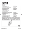
1
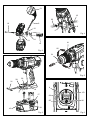
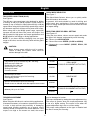
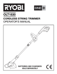
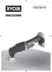
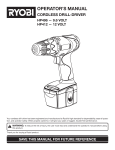
LCDI1802 18 VOLT COMPACT HAMMER DRILL DRIVER OWNER’S OPERATING MANUAL DESCRIPTION 22. Lock (tighten) 23. Unlock (release) 24. Low speed 25. High speed 26. Drive mode 27. Drill mode 28. Hammer mode 29. To increase torque 30. To decrease torque 31. Bit 32. Screws 33. Bit holder 34. Drilling depth 35. Drill bit 36. Scale 37. To increase drilling depth 38. To loosen 39. To tighten 40. To decrease drilling depth 41. Chuck sleeve 1. Keyless chuck 2. Torque adjustment ring 3. Quick mode selector 4. Two-speed gear train 5 . Rotation selector (forward/reverse/center lock) 6. Depth rod stop 7. Bit storage 8. Trigger switch 9. Mag Tray™ 10. Handle screw 11. Hex head hole 12. Handle coller 13. Teeth 14. Depth stop rod clamp 15. Auxiliary handle 16. Battery pack (Not included) 17. Latches 18. Depress latches to release battery pack 19. Reverse 20. Forward 21. Chuck jaws 1 4 3 2 6 8 5 9 7 Fig. 1 13 19 20 6 10 8 12 5 Fig. 4 11 14 41 15 22 Fig. 2 21 23 Fig. 5 31 32 33 4 9 7 17 24 25 16 LO HI 18 Fig. 3 Fig. 6 26 27 28 6 36 3 13 35 34 28 26 27 6 I Fig. 7 2 29 38 30 Fig. 8 41 22 40 21 37 39 35 23 Fig. 9 Fig. 10 Important! It is essential that you read the instructions in this manual before operating this machine. Subject to technical modifications. English General Power Tool Safety Warnings WARNING Read all safety warnings and all instructions. Failure to follow the warnings and instructions may result in electric shock, fire and/or serious injury. protected supply. Use of an RCD reduces the risk of electric shock. NOTE: The term ''residual current device (RCD)'' may be replaced by the term ''ground fault circuit interrupter (GFCI)'' or ''earth leakage circuit breaker (ELCB)''. PERSONAL SAFETY Stay alert, watch what you are doing and use common sense when operating a power tool. Do not use a power tool while you are tired or under the influence of drugs, alcohol or medication. A moment of inattention while operating power tools may result in serious personal injury. Use personal protective equipment. Always wear eye protection. Protective equipment such as dust mask, non-skid safety shoes, hard hat, or hearing protection used for appropriate conditions will reduce personal injuries. Prevent unintentional starting. Ensure the switch is in the off-position before connecting to power source and/or battery pack, picking up or carrying the tool. Carrying power tools with your finger on the switch or energising power tools that have the switch on invites accidents. Remove any adjusting key or wrench before turning the power tool on. A wrench or a key left attached to a rotating part of the power tool may result in personal injury. Do not overreach. Keep proper footing and balance at all times. This enables better control of the power tool in unexpected situations. Dress properly. Do not wear loose clothing or jewellery. Keep your hair, clothing and gloves away from moving parts. Loose clothes, jewellery or long hair can be caught in moving parts. If devices are provided for the connection of dust extraction and collection facilities, ensure these are connected and properly used. Use of dust collection can reduce dust-related hazards. Save all warnings and instructions for future reference. The term "power tool'' in the warnings refers to your mains-operated (corded) power tool or battery-operated (cordless) power tool. WORK AREA SAFETY Keep work area clean and well lit. Cluttered or dark areas invite accidents. Do not operate power tools in explosive atmospheres, such as in the presence of flammable liquids, gases or dust. Power tools create sparks which may ignite the dust or fumes. Keep children and bystanders away while operating a power tool. Distractions can cause you to lose control. ELECTRICAL SAFETY Power tool plugs must match the outlet. Never modify the plug in any way. Do not use any adaptor plugs with earthed(grounded) power tools. Unmodified plugs and matching outlets will reduce risk of electric shock. Avoid body contact with earthed or grounded surfaces, such as pipes, radiators, ranges and refrigerators. There is an increased risk of electric shock if your body is earthed or grounded. Do not expose power tools to rain or wet conditions. Water entering a power tool will increase the risk of electric shock. Do not abuse the cord. Never use the cord for carrying, pulling or unplugging the power tool. Keep cord away from heat, oil, sharp edges or moving parts. Damaged or entangled cords increase the risk of electric shock. When operating a power tool outdoors, use an extension cord suitable for outdoor use. Use of a cord suitable for outdoor use reduces the risk of electric shock. If operating a power tool in a damp location is unavoidable, use a residual current device (RCD) POWER TOOL USE AND CARE Do not force the power tool. Use the correct power tool for your application. The correct power tool will do the job better and safer at the rate for which it was designed. Do not use the power tool if the switch does not turn it on and off. Any power tool that cannot be controlled with the switch is dangerous and must be repaired. 1 English General Power Tool Safety Warnings knowledge, unless they have been given supervision or instruction concerning use of the appliance by a person responsible for their safety. Children should be supervised to ensure that they do not play with the appliance. Disconnect the plug from the power source and/ or the battery pack from the power tool before making any adjustments, changing accessories, or storing power tools. Such preventive safety measures reduce the risk of starting the power tool accidentally. Store idle power tools out of the reach of children and do not allow persons unfamiliar with the power tool or these instructions to operate the power tool. Power tools are dangerous in the hands of untrained users. Maintain power tools. Check for misalignment or binding of moving parts, breakage of parts and any other condition that may affect the power tool's operation. If damaged, have the power tool repaired before use. Many accidents are caused by poorly maintained power tools. Keep cutting tools sharp and clean. Properly maintained cutting tools with sharp cutting edges are less likely to bind and are easier to control. Use the power tool, accessories and tool bits etc. in accordance with these instructions, taking into account the working conditions and the work to be performed. Use of the power tool for operations different from those intended could result in a hazardous situation. This appliance is not intended for use by young children or infirm persons unless they have been adequately supervised by a responsible person to ensure that they do not play with the appliance. Keep children and visitors away. Visitors should wear safety glasses and be kept a safe distance from the work area. Do not let visitors contact the tool or extension cord. Complies with AS/NZS 60745. SERVICE Have your power tool serviced by a qualified repair person using only identical replacement parts. This will ensure that the safety of the power tool is maintained. SPECIAL Safety RULEs Wear ear protectors. Exposure to noise can cause hearing loss. Use auxiliary handle(s), if supplied with the tool. Loss of control can cause personal injury. Hold power tool by insulated gripping surfaces, when performing an operation where the cutting accessory may contact hidden wiring. Cutting accessory contacting a "live" wire may make exposed metal parts of the power tool "live" and could give the operator an electric shock. BATTERY TOOL USE AND CARE Recharge only with the charger specified by the manufacturer. A charger that is suitable for one type of battery pack may create a risk of fire when used with another battery pack. Use power tools only with specifically designated battery packs. Use of any other battery packs may create a risk of injury and fire. When battery pack is not in use, keep it away from other metal objects, like paper clips, coins, keys, nails, screws or other small metal objects, that can make a connection from one terminal to another. Shorting the battery terminals together may cause burns or a fire. Under abusive conditions, liquid may be ejected from the battery; avoid contact. If contact accidentally occurs, flush with water. If liquid contacts eyes, additionally seek medical help. Liquid ejected from the battery may cause irritation or burns. This appliance is not intended for use by persons (including children) with reduced physical, sensory or mental capabilities, or lack of experience and ASSEMBLY AUXILIARY HANDLE ASSEMBLY See Figure 2. An auxiliary handle is packed with the drill for ease of operation and to help prevent loss of control. The handle can be mounted on the opposite side for left or right hand use. Insert handle screw into hole located above trigger switch and seat hex head into hole. Slide handle collar onto screw, seat hex end of collar into hex hole. Hex hole for depth stop rod should be on top of collar. Slide depth stop rod into hex shaped hole on top of collar. 2 English ASSEMBLY Slide depth guide clamp into notch in collar. Clamp holds depth rod firmly in place. NOTE: When properly installed, the teeth on the depth stop rod should be aligned with the teeth indicator on the depth stop rod clamp. Thread auxiliary handle onto screw and secure tightly. NOTE: Be sure the auxiliary handle is securely tightened against the depth stop rod clamp. This secures the depth stop rod at the desired depth of cut. It also secures the auxiliary handle. SPECIFICATIONS Voltage Chuck Switch No load speed (Drill mode): -Lo speed -Hi speed Hammer speed (Blows per minute): -Lo speed -Hi speed Max. torque Weight (not incl. battery pack) MODEL BID1821 0-400 min-1 0-1500 min-1 0-5200 min-1 0-19500 min-1 49 Nm 1.68 Kg COMPATIBLE CHARGER (not included) BPL-1820 BPL-1815 BCL-1800 BCS618 ABP1801 ABP-1815 BCL-1800 BCS618 ACR1800 260022029 This product will accept RYOBI One+ 18 V lithium-ion battery packs and RYOBI One+ 18 V nickel-cadmium battery packs. BATTERY PROTECTION FEATURES RYOBI 18 V lithium-ion batteries are designed with features that protect the lithium-ion cells and maximise battery life. Under some operating conditions, these built-in features may cause the battery and the tool it is powering to act differently from nickel-cadmium batteries. During some applications, the battery electronics may signal the battery to shut down, and cause the tool to stop running. To reset the battery and tool, release the trigger and resume normal operation. NOTE: To prevent further shut down of the battery, avoid forcing the tool. If releasing the trigger does not reset the battery and tool, the battery pack is depleted. If depleted, the battery pack will begin charging when placed on the lithium-ion charger. OPERATION WARNING Do not use any attachments or accessories not recommended by the manufacturer of this product. The use of attachments or accessories not recommended can result in serious personal injury. APPLICATIONS You may use this product for the purposes listed below: Drilling in all types of wood products (lumber, plywood, panelling, composition board, and hard board) Drilling in ceramics, plastics, fiberglass, and laminates Drilling in metals Driving screws Hammer drilling in brick, or other masonry 18 V 2-13 mm Variable speed BATTERY PACK (not included) WARNING Always wear safety goggles or safety glasses with side shields when operating products. Failure to do so could result in objects being thrown into your eyes, resulting in possible serious injury. WARNING Do not allow familiarity with products to make you careless. Remember that a careless fraction of a second is sufficient to inflict serious injury. TO INSTALL BATTERY PACK See Figure 3. Lock the trigger switch by placing the rotation selector in the center position. 3 English OPERATION held in normal operating position, the rotation selector should be positioned to the left of the trigger switch for forward drilling. The drilling direction is reversed when the selector is to the right of the trigger switch. Place the battery pack on the tool. Make sure the latches on each side of the battery pack snap into place and the battery pack is secured on the tool before beginning operation. Setting the trigger switch in the OFF (center lock) position helps reduce the possibility of accidental starting when not in use. WARNING Always remove battery pack from your tool when you are assembling parts, making adjustments, cleaning, or when not in use. Removing battery pack will prevent accidental starting that could cause serious personal injury. To stop the drill, release the trigger switch and allow the chuck to come to a complete stop. TO REMOVE BATTERY PACK See Figure 3. Lock the trigger switch by placing the rotation selector in the center position. Depress the latches on the side of battery pack. Remove the battery pack from the tool. CAUTION: To prevent gear damage, always allow the chuck to come to a complete stop before changing the direction of rotation. NOTE: The drill will not run unless the rotation selector is pushed fully to the left or right. Avoid running the drill at low speeds for extended periods of time. Running at low speeds under constant usage may cause the drill to become overheated. If this occurs, cool the drill by running it without a load and at full speed. WARNING Battery tools are always in operating condition. Therefore, the switch should always be locked when not in use or carrying at your side. INTERNAL SPINDLE LOCK The internal spindle lock allows the user single-handed control of chuck adjustments and bit changes. Squeezing the chuck body stops the chuck jaws from turning. For bit changes and chuck adjustments, squeeze the chuck body and turn. TRIGGER SWITCH See Figure 4. To turn the drill ON, depress the trigger switch. To turn it OFF, release the trigger switch. KEYLESS CHUCK See Figure 5. The drill has a keyless chuck to tighten or release drill bits in the chuck jaws. The arrows on the chuck indicate which direction to rotate the chuck body in order to LOCK (tighten) or UNLOCK (release) the drill bit. VARIABLE SPEED The variable speed trigger switch delivers higher speed and torque with increased trigger pressure and lower speed with decreased trigger pressure. NOTE: You might hear a whistling or ringing noise from the switch during use. Do not be concerned; this is a normal part of the switch function. ROTATION SELECTOR (FORWARD/REVERSE/CENTER LOCK) See Figure 4. The bit rotation is reversible and is controlled by a selector located above the trigger switch. With the drill 4 WARNING Do not hold the chuck with one hand and use the power of the drill to tighten the chuck jaws on the drill bit. The chuck body could slip in your hand, or your hand could slip and come in contact with the rotating drill bit. This could cause an accident resulting in serious personal injury. English OPERATION QUICK MODE SELECTOR See Figure 7. The Quick Mode Selector allows you to quickly switch from drill mode to drive mode. In general, drill mode should be used for drilling and other heavy duty applications. Drive mode should be used for driving screws.percussion mode should be used for impact drilling. TWO-SPEED GEAR TRAIN (HI-LO) See Figure 6. The drill has a two-speed gear train designed for drilling or driving at LO (1) or HI (2) speeds. A slide switch is located on top of the drill to select either LO (1) or HI (2) speed. When using drill in the LO (1) speed range, speed will decrease and unit will have more power and torque. When using drill in the HI (2) speed range, speed will increase and unit will have less power and torque. Use LO (1) speed for high power and torque applications and HI (2) speed for fast drilling or driving applications. NOTE: If you have difficulty changing from one gear range to the other, turn the chuck by hand until the gears engage. SELECTING DRIVE OR DRILL SETTING See Figure 6-7. Using the chart below, choose correct speed and mode the type of bit, fastener, and material you will be using. Choose your APPLICATION Choose the correct SPEED: (1/LOW or 2/HIGH) Choose the correct MODE: (DRIVE, DRILL, OR HAMMER) CAUTION: Never change gears while the tool is running. Failure to obey this caution could result in serious damage to the drill. 1. APPLICATION 2. SPEED • Lag screws up to 9.5 mm dia. by 38.1 mm long • Hole saw up to 50.8 mm • Spade bits up to 38.1 mm • Drill bits up to 12.7 mm • Drilling into metal • Concrete screws 1/LOW 3. MODE DRILL MODE (TORQUE ADJUSMENT NOT ACTIVE) 2/HIGH • Drill bits up to 6.4 mm • Deck or wood screws up to 63.5 mm long • Self tapping screws 1/LOW • Deck or wood screws up to 63.5 mm long • Small screws or delicate work that requires more control 2/HIGH 1/LOW • Masonry bit up to 12.7 mm DRIVE MODE HAMMER MODE (TORQUE ADJUSMENT NOT ACTIVE) 2/HIGH TORQUE ADJUSTMENT See Figure 8. When using the drill-driver for various driving applications, it becomes necessary to increase or decrease the torque in order to help prevent the possibility of damaging screw heads, threads, workpiece, etc. In general, torque intensity should correspond to the screw diameter. If the torque is too high or the screws too small, the screws may be damaged or broken. The torque is adjusted by rotating the torque adjustment ring. The torque is greater when the torque adjustment ring is set on a higher setting. The torque is less when the torque adjustment ring is set on a lower setting. The proper setting depends on the type of material and the size of screw you are using. 5 English OPERATION INSTALLING BITS See Figure 9. Lock the trigger switch by placing the rotation selector in the center position. Open or close the chuck jaws to a point where the opening is slightly larger than the bit size you intend to use. Also, raise the front of the drill slightly to keep the bit from falling out of the chuck jaws. Insert the drill bit. Tighten the chuck jaws on the drill bit. BIT STORAGE See Figure 3. When not in use, bits provided with the drill can be placed in the storage areas located on the base of the drill. MAG TRAY™ See Figure 3. The magnetic tray conveniently stores screws or other small parts. ADJUSTING THE AUXILIARY HANDLE ASSEMBLY AND DEPTH STOP ROD See Figure 10. An auxiliary handle is packed with the drill for ease of operation and to help prevent loss of control. The handle can be mounted on the opposite side for left or right hand use. WARNING: Make sure to insert the drill bit straight into the chuck jaws. Do not insert the drill bit into the chuck jaws at an angle then tighten. This could cause the drill bit to be thrown from the drill, resulting in possible serious personal injury or damage to the chuck. NOTE: Rotate the chuck body in the direction of the arrow marked LOCK to tighten the chuck jaws. Do not use a wrench to tighten or loosen the chuck jaws. To adjust the auxiliary handle assembly: Loosen the handle assembly by turning the handle counterclockwise. Insert the auxiliary handle assembly in the desired operating position. Securely tighten by turning the auxiliary handle clockwise. NOTE: Be sure the auxiliary handle is securely tightened against the depth stop rod clamp. This secures the depth stop rod at the desired depth of cut. It also secures the auxiliary handle. REMOVING BITS See Figure 9. Lock the trigger switch by placing the rotation selector in the center position. Open the chuck jaws. NOTE: Rotate the chuck body in the direction of the arrow marked UNLOCK to loosen the chuck jaws. Do not use a wrench to tighten or loosen the chuck jaws. Remove the drill bit. The depth stop rod helps control the depth of drilled holes. For convenience and ease of starting threads, the hex nut has been trapped inside the molded slot in the auxiliary handle. DRILLING Check the rotation selector for the correct setting (forward or reverse). Secure the material to be drilled in a vise or with clamps to keep it from turning as the drill bit rotates. Hold the drill firmly and place the bit at the point to be drilled. Depress the trigger switch to start the drill. Move the drill bit into the workpiece, applying only enough pressure to keep the bit cutting. Do not force the drill or apply side pressure to elongate a hole. Let the tool do the work. To adjust the depth stop rod: Lock the trigger switch by placing the rotation selector in the center position. Loosen the auxiliary handle assembly by turning the knob counterclockwise. Adjust the depth stop rod so that the drill bit extends beyond the end of the rod to the required drilling depth. Tighten the auxiliary handle assembly by turning the knob clockwise. NOTE: When properly installed, the teeth on the depth stop rod should be aligned with the teeth indicator on the depth stop rod clamp. 6 English OPERATION WARNING: Be prepared for binding at bit breakthrough. When these situations occur, drill has a tendency to grab and kick opposite to the direction of rotation and could cause loss of control when breaking through material. If not prepared, this loss of control can result in possible serious injury. When drilling hard, smooth surfaces, use a center punch to mark the desired hole location. This will prevent the drill bit from slipping off-center as the hole is started. When drilling metals, use a light oil on the drill bit to keep it from overheating. The oil will prolong the life of the bit and increase the drilling action. If the bit jams in the workpiece or if the drill stalls, stop the tool immediately. Remove the bit from the workpiece and determine the reason for jamming. NOTE: This drill has an electric brake. When the trigger switch is released, the chuck stops turning. When the brake is functioning properly, sparks will be visible through the vent slots on the housing. This is normal and is the action of the brake. MAINTENANCE WARNING When servicing, use only identical RYOBI replacement parts. Use of any other parts may create a hazard or cause product damage. Avoid using solvents when cleaning plastic parts. Most plastics are susceptible to damage from various types of commercial solvents and may be damaged by their use. Use clean cloths to remove dirt, dust, oil, grease, etc. WARNING Do not at any time let brake fluids, gasoline, petroleumbased products, penetrating oils, etc., come in contact with plastic parts. Chemicals can damage, weaken or destroy plastic which may result in serious personal injury. Do not abuse power tools. Abusive practices can damage tool as well as workpiece. 7 WARNING Do not attempt to modify this tool or create accessories not recommended for use with this tool. Any such alteration or modification is misuse and could result in a hazardous condition leading to possible serious personal injury. 961067429-01