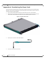
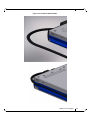
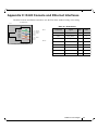
1
SwitchX 36 Port FDR IB Switch Installation Guide P/N:MSX6025T-1SFR, MSX6025T-1BRR, MSX6025F-1SFR, MSX6025F-1BRR, MSX6036T-1SFR, MSX6036T-1BRR, MSX6036F-1SFR, MSX6036F-1BRR Rev 1.5 www.mellanox.com Rev 1.5 NOTE: THIS HARDWARE, SOFTWARE OR TEST SUITE PRODUCT (“PRODUCT(S)”) AND ITS RELATED DOCUMENTATION ARE PROVIDED BY MELLANOX TECHNOLOGIES “AS-IS” WITH ALL FAULTS OF ANY KIND AND SOLELY FOR THE PURPOSE OF AIDING THE CUSTOMER IN TESTING APPLICATIONS THAT USE THE PRODUCTS IN DESIGNATED SOLUTIONS. THE CUSTOMER'S MANUFACTURING TEST ENVIRONMENT HAS NOT MET THE STANDARDS SET BY MELLANOX TECHNOLOGIES TO FULLY QUALIFY THE PRODUCTO(S) AND/OR THE SYSTEM USING IT. THEREFORE, MELLANOX TECHNOLOGIES CANNOT AND DOES NOT GUARANTEE OR WARRANT THAT THE PRODUCTS WILL OPERATE WITH THE HIGHEST QUALITY. ANY EXPRESS OR IMPLIED WARRANTIES, INCLUDING, BUT NOT LIMITED TO, THE IMPLIED WARRANTIES OF MERCHANTABILITY, FITNESS FOR A PARTICULAR PURPOSE AND NONINFRINGEMENT ARE DISCLAIMED. IN NO EVENT SHALL MELLANOX BE LIABLE TO CUSTOMER OR ANY THIRD PARTIES FOR ANY DIRECT, INDIRECT, SPECIAL, EXEMPLARY, OR CONSEQUENTIAL DAMAGES OF ANY KIND (INCLUDING, BUT NOT LIMITED TO, PAYMENT FOR PROCUREMENT OF SUBSTITUTE GOODS OR SERVICES; LOSS OF USE, DATA, OR PROFITS; OR BUSINESS INTERRUPTION) HOWEVER CAUSED AND ON ANY THEORY OF LIABILITY, WHETHER IN CONTRACT, STRICT LIABILITY, OR TORT (INCLUDING NEGLIGENCE OR OTHERWISE) ARISING IN ANY WAY FROM THE USE OF THE PRODUCT(S) AND RELATED DOCUMENTATION EVEN IF ADVISED OF THE POSSIBILITY OF SUCH DAMAGE. Mellanox Technologies 350 Oakmead Parkway Suite 100 Sunnyvale, CA 94085 U.S.A. www.mellanox.com Tel: (408) 970-3400 Fax: (408) 970-3403 Mellanox Technologies, Ltd. Beit Mellanox PO Box 586 Yokneam 20692 Israel www.mellanox.com Tel: +972 (0)74 723 7200 Fax: +972 (0)4 959 3245 © Copyright 2012. Mellanox Technologies. All Rights Reserved. Mellanox®, Mellanox logo, BridgeX®, ConnectX®, CORE-Direct®, InfiniBridge®, InfiniHost®, InfiniScale®, PhyX®, SwitchX®, Virtual Protocol Interconnect® and Voltaire® are registered trademarks of Mellanox Technologies, Ltd. Connect-IB™, FabricIT™, MLNX-OS™, ScalableHPC™, Unbreakable-Link™, UFM™ and Unified Fabric Manager™ are trademarks of Mellanox Technologies, Ltd. All other trademarks are property of their respective owners. 2 Mellanox Technologies Document Number: 3489 Rev 1.5 Switch X SX60XX 36 port FDR Switch Installation Guide Table of Contents Table of Contents 3 List of Figures 4 Revision History 5 About this Manual 6 Intended Audience Related Documentation Document Conventions Mellanox Part Numbering Legend Chapter 1 6 6 6 8 Installing the Switch in the Rack 1.1 1.2 1.3 9 Minimum and Maximum Rack Depth for these Switches. Rack Mounting 1.2.1 Installation Kits 1.2.2 Mechanical Installation Package Contents and Installation 1.3.1 Installing the Switch in the Rack 1.3.2 Grounding the Switch 1.3.3 Power Connections and Initial Power On 9 9 9 10 10 10 15 16 Chapter 2 Internally Managed Vs. Externally Managed 18 Chapter 3 Configuring the Switch 19 3.1 3.2 3.3 19 19 19 19 24 3.4 Chapter 4 Introduction Externally Managed Switches Managed (Internally Managed) Switches 3.3.1 Configuring the Switch for the First Time Rerunning the Wizard Connecting to the Switch Platform 25 4.1 4.2 4.3 25 25 26 Starting an SSH Connection to the Switch (CLI) Starting a WebUI Connection to the Switch Resetting the Switch Appendix A Transferring the Power Cord 28 Appendix B QSFP Interface 31 Appendix C RJ45 Console and Ethernet Interfaces 33 Appendix D Replacement Parts Ordering Numbers 34 Mellanox Technologies 3 Rev 1.5 List of Figures Figure 1: Rack Rail Kit Parts 11 Figure 2: Placement of Switch in Rack 12 Figure 3: Mounting Options 13 Figure 4: Screwing on the Rail 13 Figure 5: Inserting the Caged Nuts 14 Figure 6: Slide the Rail into the Rail Slide 14 Figure 7: Status LEDs 5 Minutes After Power On 15 Figure 8: Two Power Inlets - Electric Caution Notifications 17 Figure 9: Console Port 19 Figure 10: Web UI Login Page 26 Figure 11: Reset Button 26 Figure 12: Transfer Power Cord 28 Figure 13: Install the Switch Slide 29 Figure 14: Transfer Power Cord Finished 30 4 Mellanox Technologies Rev 1.5 Switch X SX60XX 36 port FDR Switch Installation Guide Revision History Table 1 - Revision History of this Installation Guide Revision Date Details 1.5 September 2012 Reduced the OPNs on the title page to those in the Price book. 1.4 August 2012 Converted Visio graphics to Mechanical drawings Added figure 2. 1.3 January 2012 Fixed wizards, Added IPv6 1.2 Oct. 2011 Removed clip references from Appendix A. 1.1 July 17, 2011 Replaced the reference to Har 000022. Har 000022 is now in the MTUSB kit and not packed with the switch. 1.0 July 04, 2011 Initial release Mellanox Technologies 5 Rev 1.5 About this Manual This manual describes the installation and set-up instructions of the Mellanox SX60XX switch family, which is based on the SwitchX IB switch device. Intended Audience This manual is intended for users and system administrators responsible for installing and setting up the switch platform. The manual assumes familiarity with the InfiniBand® architecture specification. Related Documentation The documentation set accompanying the SX60XX top of rack switch platform includes the following: Table 2 - Reference Documents Document Name Description InfiniBand Architecture Specification, Vol. 1, Release 1.2.1 The InfiniBand Architecture Specification that is provided by IBTA Switch Hardware User Manual This document contains HW descriptions, LED assignments and HW specifications among other things. Mellanox MLNX-OS SwitchX Software User Manual This document contains information regarding configuring and managing Mellanox Technologies’ SwitchX Switch Platforms. MLNX-OS Software WebUI User’s Manual WebUI user’s manual for MLNX-OS MLNX-OS Software Command Reference Guide Command Reference Guide for MLNX-OS listing all of the commands available through MLNX-OS with explanations and examples. MLNX-OS Software Configuration Guide Configuration Guide for MLNX-OS displaying different configuration scenarios. All of these documents can be found on the Mellanox Website. They are available either through the product pages or through the support page with a login of user and password. Document Conventions When discussing memory sizes, MB and MBytes are used in this document to mean size in mega bytes. The use of Mb or Mbits (small b) indicates size in mega bits. 6 Mellanox Technologies Rev 1.5 Switch X SX60XX 36 port FDR Switch Installation Guide This symbol makes recommendations to the user. This symbol indicates information that is helpful to the user. This symbol indicates a situation that can potentially cause damage to hardware or software. BEWARE! This symbol indicates a situation that can potentially cause personal injury or damage to hardware or software. Mellanox Technologies 7 Rev 1.5 Mellanox Part Numbering Legend Mellanox Part Numbering Legend Place Field M Decoder Mellanox Technologies SX System Type SwitchX Switch P Protocol 60 = IB 90 = VPI MM Port and 25 = 36 Ports externally managed Management 36 = 36 ports internally managed Options C InfiniBand Port Config - Separator P # Power Sup- 0=0, 1=1, 2=2.... plies F Form factor S = standard depth, B = short depth Y Air Flow direction R= Connector side to PSU side airflow RoHS R = RoHS6 R 8 Mellanox Technologies F = FDR, T = FDR10, Q = QDR, D = DDR F= PSU side to Connector side airflow Rev 1.5 Switch X SX60XX 36 port FDR Switch Installation Guide 1 Installing the Switch in the Rack 1.1 Minimum and Maximum Rack Depth for these Switches. This switch can be installed in any standard 19” rack with depths of 40cm to 80cm. Make sure that the Installation kit you have is compatible with your rack. To use the SwitchX series switch in a rack deeper than 60cm, order the switch with the standard depth, or order the MSX60-SKIT installation kit. The both of these solutions will allow you to install the switch in a 19” rack whose vertical supports are between 60cm and 80cm apart. 1.2 Rack Mounting The switch platform can be rack mounted and is designed for installation in a standard 19” rack. The power side of the switch includes a hot-swap power supply module, a blank cover for an optional second PSU for redundancy, and a hot-swap fan tray. There are two possible air flow directions. Be sure that the switch air flow direction is compatible with your system, rack, and PSUs. The connector side of the switch has the QSFP ports, system LEDs, and management connection ports. The switch platform contains auto-sensing 100 - 240 VAC connections for all possible PSUs. The installer should use a rack capable of supporting the mechanical and environmental characteristics of a fully populated platform. The rack mounting holes conform to the EIA-310 standard for 19-inch racks. Take precautions to guarantee proper ventilation in order to maintain good airflow at ambient temperature. Cable routing in particular should not impede the air exhaust from the chassis. 1.2.1 Installation Kits There are two Installation kit options. One long and one short. Both the standard and the short switches can be mounted using the long rail kit. The short kit will only work with the short switch. See “Mellanox Part Numbering Legend” on page 8 for explanation of the switch depth according to the Model numbers. Table 3 - Installation Kit According to Rack Size Kit OPN Rack Size MSX60-BKIT 40-60 cm MSX60-SKIT 60-80 cm Mellanox Technologies 9 Rev 1.5 Installing the Switch in the Rack 1.2.2 Mechanical Installation The switch platform can be rack mounted and is designed for installation in a standard 19” rack. The power side of the switch includes a hot-swap power supply module, a blank cover for an optional second PS unit for redundancy, and a hot-swap fan tray. There are two possible air flow directions. Be sure that the switch air flow direction is compatible with your system, rack, and PS units. The connector side of the switch has the QSFP ports, system LEDs, and management connection ports. The switch platform contains auto-sensing 100 - 240 VAC connections for all possible PS units. The installer should use a rack capable of supporting the mechanical and environmental characteristics of a fully populated platform. The rack mounting holes conform to the EIA-310 standard for 19-inch racks. Take precautions to guarantee proper ventilation in order to maintain good airflow at ambient temperature. Cable routing in particular should not impede the air exhaust from the chassis. 1.3 Package Contents and Installation Before you install your new SX6036 switch, unpack the system and check to make sure that all the parts have been sent, check this against the parts list below. Check the parts for visible damage that may have occurred during shipping. The switch comes packed with the following items: • 1 X – switch • 1 X – installation kit • 1 X – power cable for each PS unit – Type C13-C14 See “Replacement Parts Ordering Numbers” on page 34 to order power cords for various countries. A single power cord for each power supply unit can be ordered at no extra charge • 1 X – Harness HAR000028 – Harness RS232 2M cable – DB9 to RJ-45 for SX6036 switches • 1 X – Quick Start Guide • 1 X – China RoHS statement If anything is damaged or missing, contact your customer representative immediately. For customer support go to: www.mellanox.com =>Support => Customer Support Portal Login 1.3.1 Installing the Switch in the Rack Tools and Customer Supplied Parts: • Phillips Screwdrivers #1 and #2 • ESD strap • ESD mat 10 Mellanox Technologies • Grounding screw • Grounding wire sufficient to reach a valid ground. Rev 1.5 Switch X SX60XX 36 port FDR Switch Installation Guide For racks from 60cm to 80cm deep either use the standard depth switches with the long rail kit or the short switches with the long rail kit. Parts included in the rail kit: • 2 rails • 2 rail slides • 2 switch slides • 16 recessed flat head screws You will have extras! • 10 caged nuts • 10 pan head screws M6 Figure 1: Rack Rail Kit Parts Switch slide x2 Rail x2 Rail slide x2 1. 2. Place the ESD mat on the floor where you will be working and put on the ESD strap. Make sure the ESD strap is touching your skin and that the other end is connected to a verified ground. Choose which side of the switch you want even with the rack vertical support. Either the side with the power supply units or the side with the QSFP connectors can be even with one of the vertical rack supports. Mellanox Technologies 11 Rev 1.5 Installing the Switch in the Rack Figure 2: Placement of Switch in Rack Doors Connector side Cable with recommended bending radius 19" (482.6mm) Switch Insufficient room for recommended bending radius Spine side Doors Things to consider before choosing where to mount the rails and rail slides. The distance between the rack and the door can be as little as 4 cm on one side of the rack and as much as 18 cm on the other side of the rack. Keep in mind that there can be as many as 3618 cables connected to the switch. Do you want the connector side recessed in the rack to allow for a larger cable bending radius? It is possible to recess the connector side by 5cm by optional placement of the switch rails. See Figure 3,“Mounting Options”. Will the connector side be recessed past other equipment in the rack and will this be prob- lematic? The installation kit allows for a 2” recess of the switch past the vertical support. 12 Mellanox Technologies Rev 1.5 Switch X SX60XX 36 port FDR Switch Installation Guide Figure 3: Mounting Options 3. Decide which mounting option you want to use. To use the rail kit to transfer the power cord from the connector side to the power side go now to “Transferring the Power Cord” on page 28. 4. Screw the switch slides onto the switch. Use 5 flat head screws for short switches and 7 screws for standard depth switches, to connect each switch slide. Figure 4: Screwing on the Rail 5 screws per side are needed for the short switch 7 screws per side are needed for the standard switch There are 16 screws in the kit; you will have left over screws. Mellanox Technologies 13 Rev 1.5 Installing the Switch in the Rack Figure 5: Inserting the Caged Nuts Side you will slide the switch into Second side 5. 6. 7. 8. Clip 6 caged nuts into the holes in the rack on the side of the rack you will be sliding the switch into. Check that both sides of the switch, power side and connector side, are at the same level in the rack. Clip 4 more caged nuts into the holes on the opposite side of the rack. Check that both sides of the switch, left and right, are the same level in the rack. Slide the rail into the rail slide. Using two of the bolts for each corner install the rails and rail slides in the rack. Do not tighten the bolts yet. Figure 6: Slide the Rail into the Rail Slide This side of the rail kit goes on the side of the rack you will slide the switch into. This is the same side of the switch that will be next to the vertical support. 14 Mellanox Technologies Rev 1.5 Switch X SX60XX 36 port FDR Switch Installation Guide 9. 10. 11. 12. 13. 14. Slide the switch into the rails. Tighten the bolts to 9.2 Nm or 81.5 pound inches. Put the switch into place and screw the bolts into the nuts. Tighten the bolts to 9.2 Nm or 81.5 pound inches. Ground the switch. Plug in the power cables. Check the Status LEDs and confirm that all of the LEDs show status lights consistent with normal operation. Figure 7: Status LEDs 5 Minutes After Power On Warning: Any yellow or red status LEDs are cause for concern and must be dealt with immediately. It can take up to 5 minutes to boot up, during which time the status LED may indicate red. 15. You can start connecting all of the cables to the switch. FDR and FDR10 are only guaranteed to work with approved Mellanox Cables. Caution: Slide/rail mounted equipment is not to be used as a shelf or a work space. 1.3.2 Grounding the Switch Check to determine if your local or national electrical codes require an external ground to all IT components. If so, connect a ground wire to one of the casing screws and connect the other end to a valid ground. If you choose to not use the ground screw, make sure that the rack is properly Mellanox Technologies 15 Rev 1.5 Installing the Switch in the Rack grounded and that there is a valid ground connection between the chassis of the switch and the rack. Test the ground using an Ohm meter. Some national and/or local codes may require IT components to be bonded and externally grounded (not including the power cord ground). You must follow all national and local codes when installing this equipment. 1.3.3 Power Connections and Initial Power On The switch platform ships with one or two Power Supply Units. For switches with only one unit installed, a second PSU may be installed at a later time. Each supply has a separate AC receptacle. The input voltage is auto-adjusting for 100 - 240 VAC, 50-60Hz power connections. The power cords should be standard 3-wire AC power cords including a safety ground and rated for 15A or higher. Caution: The switch platform will automatically power on when AC power is applied. There is no power switch. Check all boards, power supplies, and fan tray modules for proper insertion before plugging in a power cable. Caution: After inserting a power cable and confirming the green system status LED light is on; make sure that the Fan Status indicator shows green. If the fan status indicator is not green then unplug the power connection and check that the fan module is inserted properly and that the mating connector of the fan unit is free of any dirt and/or obstacles. Caution: When turning off the switch, make sure ALL Connector LEDS are off to ensure a powered down status. 16 Mellanox Technologies Rev 1.5 Switch X SX60XX 36 port FDR Switch Installation Guide Do not hot swap the power supply if your switch has only one power supply. You must power down the system to replace the power supply unit when there is only one PSU in the switch. Figure 8: Two Power Inlets - Electric Caution Notifications CAUTION Risk of electric shock and energy hazard. The two PSUs are independent. Disconnect all power supplies to ensure a powered down state inside of the switch platform. ACHTUNG Gafahr des elektrischen Schocks. Entferrnen des Netzsteckers elnes Netzteils spannungsfrei. Um alle Einhieten spannungsfrei zu machen sind die Netzstecker aller Netzteile zu entfernen ATTENTION Risque de choc et de danger e’lectriques. Le de’branchment d’une seule alimentation stabilise’e ne de’branch uniquement qu’un module “Alimentation Stabilise’e”. Pour isoler completement le module en cause, Il faut de’brancher toutes les alimentations stabilise’es. Mellanox Technologies 17 Rev 1.5 2 Internally Managed Vs. Externally Managed Internally Managed Vs. Externally Managed The following table shows which switches come with a management CPU and which do not. Externally managed (unmanaged) switches are plug and play out of the box. All switches come with the latest firmware burned on the flash. Updating the firmware stack for the externally managed switches is done in-band only. When a new firmware release is available (e-mail notification) you can upgrade the device through a link to the Mellanox web-page firmware download site. All internally managed switches have internal chassis management and can support IB fabric of up to 648 nodes. Internally managed switches need an initial configuration before they will start working. Table 4 - Switch Management Family 18 Internally/ Externally Managed Management Connections SX6025 Externally managed (unmanaged) Plug and Play All firmware updates should be done in-band using Mellanox firmware management tools. I2C port access using MTUSB-1 device is required for firmware updates if in-band burning is not possible. SX6036 Internally managed RS232 cable DB9 to RJ45 included in the box to connect to host PC for initial configuration of the switch. After initial configuration the switch can be managed through the Ethernet port using a remote connection. Mellanox Technologies Rev 1.5 Switch X SX60XX 36 port FDR Switch Installation Guide 3 Configuring the Switch 3.1 Introduction The procedures described in this chapter assume that you have already installed and powered-on your switch according to the instructions in the Switch Installation Guide, this document. 3.2 Externally Managed Switches Unmanaged (Externally managed) switches, that is the SX6025 switches, do not get configured. On unmanaged switches, the CONSOLE, Ethernet, and USB connectors are not found do not work. Instead there is an I2C connector. The unmanaged switches are Plug and Play and all firmware updates should be done in-band. The I2C connection should only be used if the firmware image was corrupted to the point that the regular firmware tools cannot successfully reburn the correct image. When you install the switch, it comes with the latest firmware burned on the board. You will not need to burn firmware unless you get notification from Mellanox that a newer version of firmware for your switch has been released. 3.3 Managed (Internally Managed) Switches Internally managed switches must be configured before they will work. Follow the procedures below to configure the switch. 3.3.1 Configuring the Switch for the First Time Step 1. Connect the host PC to the Console (RJ-45) port of the switch system using the supplied cable. The Console ports for SX60XX systems are shown below as examples. Figure 9: Console Port 1 34 35 36 MGT 2 SX6036 CONSOLE Connect the host PC to here. Mellanox Technologies 19 Rev 1.5 Configuring the Switch Make sure to connect to the Console RJ-45 port of the switch and not to the (Ethernet) MGT port. No remote IP connection is available at this stage. Configure a serial terminal program (for example, HyperTerminal, minicom, or Tera Term) on your host PC with the settings described in Table 5. Step 2. Table 5 - Serial Terminal Program Configuration Parameter Setting Baud Rate 9600 Data bits 8 Stop bits 1 Parity None Flow Control None Step 3. Login (from a serial terminal program) as admin and use admin as password. This starts the Mellanox configuration wizard. Step 4. Go through the Mellanox configuration wizard. Table 6 shows an example of a wizard session. Table 6 - Configuration Wizard Session - IP Configuration by DHCP (Sheet 1 of 2) Wizard Session Display (Example) 20 Comments Mellanox configuration wizard Do you want to use the wizard for initial configuration? yes You must perform this configuration the first time you operate the switch or after resetting the switch. Type ‘y’ and then press <Enter>. Step1: Hostname? [switch-1] If you wish to accept the default hostname, then press <Enter>. Otherwise, type a different hostname and press <Enter>. Mellanox Technologies Rev 1.5 Switch X SX60XX 36 port FDR Switch Installation Guide Table 6 - Configuration Wizard Session - IP Configuration by DHCP (Sheet 2 of 2) Wizard Session Display (Example) Step 2: Use DHCP on mgmt0 interface? [no] Comments Perform this step to obtain an IP address for the switch. (eth0 is the management port of the switch.) If you wish the DHCP server to assign the IP address, type ‘yes’ and press <Enter>. If you type ‘no’ (no DHCP), then you will be asked whether you wish to use the ‘zeroconf’ configuration or not. If you enter ‘yes’ (yes Zeroconf), the session will continue as shown in Table 7. If you enter ‘no’ (no Zeroconf), then you need to enter a static IP, and the session will continue as shown in Table 8. Step 3: Enable IPv6? [yes] yes The management interface will be able to use IPv6 addresses. Step 4: Enable IPv6 autoconfig (SLAAC) on mgmt0 interface? [no] no This turns on autoconfiguration of the IPv6 addresses. This is unsuitable for DHCPv6. Step 5: Admin password (Press <Enter> to leave unchanged)? <new_password> Step 6: Confirm admin password? <new_password> To avoid illegal access to the machine, please type a password and then press <Enter>. Then confirm the password by re-entering it. Note that password characters are not printed. You have entered the following information: 1. Hostname: <switch name> 2. Use DHCP on mgmt0 interface: yes 3. Enable IPv6: yes 4. Enable IPv6 autoconfig (SLAAC) on mgmt0 interface: no 5. Admin password (Enter to leave unchanged): (CHANGED) To change an answer, enter the step number to return to. Otherwise hit <enter> to save changes and exit. The wizard displays a summary of your choices and then asks you to confirm the choices or to re-edit them. Either press <Enter> to save changes and exit, or enter the configuration step number that you wish to return to. Note: To run the command “configuration jump-start” you must be in Config mode. Choice: <Enter> Configuration changes saved. To return to the wizard from the CLI, enter the “configuration jump-start” command from configuration mode. Launching CLI... <switch name> [> Mellanox Technologies 21 Rev 1.5 Configuring the Switch Table 7 - Configuration Wizard Session - IP Zeroconf Configuration Wizard Session Display - IP Zeroconf Configuration (Example) Mellanox configuration wizard Do you want to use the wizard for initial configuration? y Step 1: Hostname? [switch-112126] Step 2: Use DHCP on mgmt0 interface? [yes] no Step 3: Use zeroconf on mgmt0 interface? [no] yes Step 4: Default gateway? [For example:192.168.10.1] Step 5: Primary DNS server? Step 6: Domain name? Step 7: Enable IPv6? [yes] yes Step 8: Enable IPv6 autoconfig (SLAAC) on mgmt0 interface? [no] no Step 9: Admin password (Enter to leave unchanged)? Step 9: Confirm admin password? (Enter to leave unchanged)? You have entered the following information: 1. Hostname: switch-112126 2. Use DHCP on mgmt0 interface: no 3. Use zeroconf on mgmt0 interface? [no] yes 4. Default gateway: 192.168.10.1 5. Primary DNS server: 6. Domain name: 7. Enable IPv6: yes 8. Enable IPv6 autoconfig (SLAAC) on mgmt0 interface: no 9. Admin password (Enter to leave unchanged): (unchanged) To change an answer, enter the step number to return to. Otherwise hit <enter> to save changes and exit. Choice: Configuration changes saved. To return to the wizard from the CLI, enter the "configuration jump-start" command from configure mode. Launching CLI... switch-1 > 22 Mellanox Technologies Rev 1.5 Switch X SX60XX 36 port FDR Switch Installation Guide Table 8 - Configuration Wizard Session - Static IP Configuration Wizard Session Display - Static IP Configuration (Example) Mellanox configuration wizard Do you want to use the wizard for initial configuration? y Step 1: Hostname? [switch-112126] Step 2: Use DHCP on mgmt0 interface? [yes] n Step 3: Use zeroconf on mgmt0 interface? [no] Step 4: Primary IP address? [for example 192.168.10.4] Mask length may not be zero if address is not zero (interface eth0) Step 5: Netmask? [0.0.0.0] 255.255.255.0 Step 6: Default gateway? [for example 192.168.10.1] Step 7: Primary DNS server? Step 8: Domain name? Step 9: Enable IPv6? [yes] yes Step 10: Enable IPv6 autoconfig (SLAAC) on mgmt0 interface? [no] no Step 11: Admin password (Enter to leave unchanged)? You have entered the following information: 1. Hostname: switch-112126 2. Use DHCP on mgmt0 interface: no 3. Use zeroconf on mgmt0 interface: no 4. Primary IP address: 192.168.10.4 5. Netmask: 255.255.255.0 6. Default gateway: 192.168.10.1 7. Primary DNS server: 8. Domain name: 9. Enable IPv6: yes 10.Enable IPv6 autoconfig (SLAAC) on mgmt0 interface: no 11.Admin password (Enter to leave unchanged): (unchanged) To change an answer, enter the step number to return to. Otherwise hit <enter> to save changes and exit. Choice: Configuration changes saved. To return to the wizard from the CLI, enter the "configuration jump-start" command from configure mode. Launching CLI... switch-1 > Step 5. Before attempting a remote (for example, SSH) connection to the switch, check the mgmt0 interface configuration. Specifically, verify the existence of an IP address. To check the current mgmt0 configuration, enter the following commands: sx-43 [standalone: master] > enable sx-43 [standalone: master] # show interfaces mgmt0 Mellanox Technologies 23 Rev 1.5 Configuring the Switch The following is an example of the output: Interface mgmt0 state Admin up: yes Link up: yes IP address: 192.168.10.43 Netmask: 255.255.255.0 Speed: 1000Mb/s (auto) Duplex: full (auto) Interface type: ethernet Interface source: physical MTU: 1500 HW address: 00:02:C9:11:2A:AE Comment: RX bytes: 1343502058 TX bytes: 313920869 RX packets: 17589211 TX packets: 992717 RX mcast packets: 0 TX discards: 0 RX discards: 0 TX errors: 0 RX errors: 0 TX overruns: 0 RX overruns: 0 TX carrier: 0 RX frame: 0 TX collisions: 0 TX queue len: 3.4 Rerunning the Wizard If you want to rerun the wizard run the following commands: sx-43 [standalone: master] > enable sx-43 [standalone: master]# configure terminal sx-43 [standalone: master]# configuration jump-start 24 Mellanox Technologies 1000 Rev 1.5 Switch X SX60XX 36 port FDR Switch Installation Guide 4 Connecting to the Switch Platform 4.1 Starting an SSH Connection to the Switch (CLI) Step 1. Set up an Ethernet connection between the switch and a local network machine (“the remote machine” henceforth) using a standard RJ-45 connector. Step 2. Connect to the remote machine (rem_mach1 is used as an example). Step 3. Start a remote shell to the switch using the following command using <switch_IP_address> is the IP address of the switch or its DNS name. rem_mach1 > ssh -l <username> <switch ip address> Mellanox MLNX-OS Switch Management Password: Last login: Thu Apr 28 11:24:13 2011 from 192.168.10.1 Mellanox Switch sx-43 [standalone: master] > Step 4. 4.2 You can enter any supported command now. Starting a WebUI Connection to the Switch Step 1. Set up an Ethernet connection between the switch and a local network machine (“the remote machine” henceforth) using a standard RJ-45 connector. Step 2. Start a Web browse – Google Chrome, Microsoft Internet Explorer 7.0 or Mozilla Firefox 3.0. Make sure the screen resolution is set to 1024*768 or higher. Step 3. Enter as URL the following: http://<switch_IP_address> where <switch_IP_address> is the IP address of the switch or its DNS name. Mellanox Technologies 25 Rev 1.5 Connecting to the Switch Platform Step 4. You will receive the login window for remote management of the switch. The following figure shows an example. Note that the default username is admin Figure 10: Web UI Login Page 4.3 Resetting the Switch On the connector side panel under the system LEDs is a reset button. This reset button requires a tool to be pressed. DO NOT use a sharp pointed object such as needle or push pin for pressing the Reset button. Sharp objects can cause damage, use a flat object to press this reset button. Figure 11: Reset Button Press the reset button to reset the main and management CPUs and to delete the existing password. ! PS1 PS2 ! UID RST 26 Mellanox Technologies 1 2 Rev 1.5 Switch X SX60XX 36 port FDR Switch Installation Guide This button resets both the CPU of the switch device and the CPU of the management module. It thereby resets all of the ports by bringing them down and powering them up when the button is pushed. A quick push of this button performs this reset. When the button is held down for 15 seconds the switch is reset and the password is deleted. You will then be able to enter without a password and make a new password for the user admin. The SwitchX Series User Manuals can be found at: http://www.mellanox.com Mellanox Technologies 27 Rev 1.5 Connecting to the Switch Platform Appendix A: Transferring the Power Cord To use the rail kit to transfer the power cord from the connector side to the power side follow these directions. Do you want to install power cords on both sides of the switch or only one side? For each power cord you want to transfer: 1. 2. Once you have decided which side of the switch will be next to the vertical support? Make sure that you place the cord so that the correct end of the cord will be at the power side of the switch. This will depend on which of the four mounting options you choose. Figure 12: Transfer Power Cord 28 3. Put the power cord in the switch slide channel. 4. Screw the switch slides to the switch. Mellanox Technologies Rev 1.5 Switch X SX60XX 36 port FDR Switch Installation Guide Figure 13: Install the Switch Slide Mellanox Technologies 29 Rev 1.5 Connecting to the Switch Platform Figure 14: Transfer Power Cord Finished 5. 30 Return to step 4 on page 13 and continue the installation. Mellanox Technologies Rev 1.5 Switch X SX60XX 36 port FDR Switch Installation Guide Appendix B: QSFP Interface 20 21 22 23 24 25 26 27 28 29 30 31 19 GND GND Rx2n Rx1n 18 Rx2p Rx1p 17 GND GND 16 Rx4n Rx3n Rx4p Rx3p GND GND ModPrsL SDA IntL SCL VccTx Vcc Rx Vcc1 ResetL LPMode ModSelL 32 GND GND 33 Tx3p Tx4p 15 14 Signal Description GND Ground 2 Tx2n Transmitter Inverted Data Input 3 Tx2p Transmitter Non-Inverted Data Input 10 4 GND Ground 9 5 Tx4n Transmitter Inverted Data Input 8 6 Tx4p Transmitter Non-Inverted Data Input 7 7 GND Ground 6 8 ModSelL Module Select 9 ResetL Module Reset 10 Vcc Rx 11 SCL 2-wire serial interface clock 12 SDA 2-wire serial interface data 13 GND Ground 12 11 Tx3n 35 GND Tx4n GND 36 Tx1p Tx2p 3 Tx1n GND Tx2n GND 2 1 38 Connector Connector Pin Pin Name Number 1 13 34 37 Table 9 - QSFP Connector Pinout 5 4 +3.3 V Power supply receiver 14 Rx3p Receiver Non-Inverted Data Output 15 Rx3n Receiver Inverted Data Output 16 GND Ground 17 Rx1p Receiver Non-Inverted Data Output 18 Rx1n Receiver Inverted Data Output 19 GND Ground 20 GND Ground 21 Rx2n Receiver Inverted Data Output 3 22 Rx2p Receiver Non-Inverted Data Output 3 23 GND Ground 24 Rx4n Receiver Inverted Data Output 3 25 Rx4p Receiver Non-Inverted Data Output 3 26 GND 27 ModPrsL Ground Module Present 28 IntL 29 Vcc Tx +3.3 V Power supply transmitter Interrupt 30 Vcc 1 +3.3 V Power Supply 31 LPMode 32 GND Ground 33 Tx3p Transmitter Non-Inverted Data Input 34 Tx3n Transmitter Inverted Data Input 35 GND Ground Low Power Mode 36 Tx1p Transmitter Non-Inverted Data Input 37 Tx1n Transmitter Inverted Data Input 38 GND Ground Mellanox Technologies 31 7 8 11 1 0 9 12 13 14 15 16 17 18 19 ModSelL ResetL SCL SDA GND RX3p RX3n GND RX1p RX1n GND VccRx 6 GND 20 GND 21 RX2n 22 RX2p 23 GND 24 RX4n 25 RX4p 26 GND 27 ModPrsL 28 IntL 29 VccTx 30 Vcc1 31 LPMode 14 13 12 11 1 0 9 8 7 6 5 4 3 2 1 GND 32 GND TX2n 5 TX4p 15 TX2p 33 TX3p 16 GND 34 TX3n TX4n 4 TX4n TX4p 19 18 17 GND 35 GND ModSelL 3 GND ResetL 36 TX1p SCL 2 TX2p SDA 37 TX1n GND 1 TX2n RX3p 38 GND GND 3 8 TX1n 3 7 TX1p 3 6 GND 3 5 TX3n 3 4 TX3p 3 3 GND 3 2 LPMode 3 1 Vcc1 30 RX3n VccRx GND RX1n RX1p GND GND Top 18.35 Top 18.35 View into Rear of Connector VccTx 29 IntL 28 ModPrsL 27 GND 26 RX4p 25 RX4n 24 GND 23 RX2p 22 RX2n 21 GND 20 Mellanox Technologies 32 Connecting to the Switch Platform Rev 1.5 8.50 View into Front of Cage 8.50 Rev 1.5 Switch X SX60XX 36 port FDR Switch Installation Guide Appendix C: RJ45 Console and Ethernet Interfaces The RJ45 Console and Ethernet interfaces uses the EIA 568A standard wiring color coding. C O N SO LE J34 Table 10 - RJ45 Pinout TXD+ TXDRXD+ GND GND RXDGND GND L o o k in g in to th e S o c k e t R J45_R T S # R J45_D T R # R J45_T X D GND GND R J45_R X D GND GND P in 1 Connection Signal Pin# Color TXD+ RJ45_RTS# 1 G/W TXD- RJ45_DTR# 2 G RXD+ RJ45_TXD 3 O/W GND GND 4 Bl GND GND 5 Bl/W RXD- RJ45_RXD 6 O GND GND 7 Br/w GND GND 8 Br P in 8 Mellanox Technologies 33 Rev 1.5 Connecting to the Switch Platform Appendix D: Replacement Parts Ordering Numbers Table 11 - Replacement Parts Ordering Numbers Part Description 34 OPN I2C DB9 or RJ45 to USB Adapter MTUSB-1 Fan module with power supply side to connector side air flow MSX60-FF Fan module with connector side to power supply side air flow MSX60-FR 300W Power Supply w/ Power Supply Side to Connector side air flow MSX60-PF 300W Power Supply w/ Connector side to Power Supply side air flow MSX60-PR Power cord Type C13-C14 ACC000251 Power cord Type B for USA, Canada, Mexico, Taiwan ACC000204 Power cord Type H for Israel ACC000205 Power cord Type E/F for Sweden, France, Germany, Netherlands, Russia ACC000207 Power cord Type G for UK ACC000208 Power cord Type D for India ACC000209 Power cord Type I for China ACC000210 Power cord Type J for Switzerland ACC000211 Power cord Type B for Japan, ACC000212 Power cord Type I for Australia ACC000213 Installation Kit for short switches in racks 40-60 cm deep MSX60-BKIT Installation Kit for short or standard switches in racks 60-80 cm deep MSX60-SKIT Mellanox Technologies