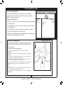
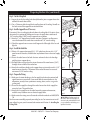
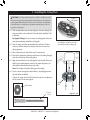
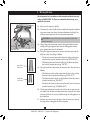
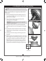
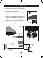
1
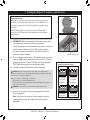
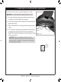
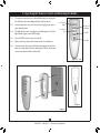
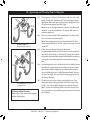
For Your Records and
Warranty Assistance
For reference, also attach your receipt or a copy
of your receipt to the manual.
__________________________________________
Model Name
Type 3 Models
Owner’s Guide and Installation Manual
__________________________________________
Model No.
__________________________________________
Date Purchased
__________________________________________
Where Purchased
English
Español
Form# 42441-01
20110614
©2011 Hunter Fan Co.
Welcome
Your new Hunter® ceiling fan is an addition to your home or office that
will provide comfort and performance for many years. This installation
and operation manual gives you complete instructions for installing
and operating your fan.
We are proud of our work. We appreciate the opportunity to supply
you with the best ceiling fan available anywhere in the world.
Before installing your fan, for your records and warranty assistance,
record information from the carton and Hunter nameplate label
(located on the top of the fan motor housing).
Cautions and Warnings
Table Of Contents
1 • Getting Ready . . . . . . . . . . . . . . . . . . . . . . 6
2 • Installing the Ceiling Plate . . . . . . . . . . 7
3 • Assembling and Hanging the Fan . . . 8
4 • Setting the Remote Transmitter and
Receiver . . . . . . . . . . . . . . . . . . . . . . . . . . . 9
5 • Wiring the Fan . . . . . . . . . . . . . . . . . . . . . 10
6 • Installing the Canopy and Canopy Trim
Ring . . . . . . . . . . . . . . . . . . . . . . . . . . . . . . . 11
7 • Assembling the Blades . . . . . . . . . . . . . . 12
8 • Completing Your Installation With a
Light Fixture . . . . . . . . . . . . . . . . . . . . . . . 13
9 • Operating the Remote Control and
Mounting the Holder . . . . . . . . . . . . . . 16
10 • Operating and Cleaning Your Ceiling
Fan . . . . . . . . . . . . . . . . . . . . . . . . . . . . . . . . 17
11 • Troubleshooting . . . . . . . . . . . . . . . . . . . 18
© 2011 Hunter Fan Company
• READ THIS ENTIRE MANUAL CAREFULLY BEFORE BEGINNING
INSTALLATION. SAVE THESE INSTRUCTIONS.
• Use only Hunter replacement parts.
• To reduce the risk of personal injury, attach the fan directly to the
support structure of the building according to these instructions,
and use only the hardware supplied.
• To avoid possible electrical shock, before installing your fan,
disconnect the power by turning off the circuit breakers to the
outlet box and associated wall switch location. If you cannot lock
the circuit breakers in the off position, securely fasten a prominent
warning device, such as a tag, to the service panel.
• All wiring must be in accordance with national and local electrical
codes and ANSI/NFPA 70. If you are unfamiliar with wiring, use a
qualified electrician.
• To reduce the risk of personal injury, do not bend the blade
attachment system when installing, balancing, or cleaning the fan.
Never insert foreign objects between rotating fan blades.
• To reduce the risk of fire, electrical shock, or motor damage, do not
use a solid-state speed control with this fan. Use only Hunter speed
controls, which are solid state.
• This product conforms to UL STD 507 and is certified to STD C22.2
No.113
• Wash your hands after your fan installation is complete.
2
42441-01 • 06/14/11 • Hunter Fan Company
Preparing the Fan Site
Step 1 - Choose the Fan Site
Proper ceiling fan location and attachment to the building
structure are essential for safety, reliable operation, maximum
efficiency, and energy savings.
Choose a fan site where:
• No object can come in contact with the rotating fan blades during
normal operation.
• The fan blades are at least 7 feet above the floor and the ceiling is
at least 8 feet high.
• The fan blades have no obstructions to airflow, such as walls or
posts, within 30 inches of the fan blade tips.
• The fan is directly below a joist or support brace that will hold the
outlet box and the full weight of the fan.
Checklist for Existing Fan Site
If you want to use an existing fan site, complete the following checklist to
determine if the site is acceptable and safe for your new Hunter fan. If you
cannot check off every item, prepare a new fan site as described on this
page.
Fan Support System
• Fan attaches directly to building structure.
• Fan support system will hold full weight of the fan and light kit.
Ceiling Hole
• The outlet box clearance hole is directly below the joist or support brace.
Outlet Box
• The outlet box is an UL-approved octagonal 4” x 1-1/2” outlet box (or as
specified by the support brace manufacturer).
• The outlet box is secured to the joist or support brace by wood screws
and washers through the inner holes of outlet box.
• The outer holes of the outlet box are aligned with joist or support brace.
• The bottom of the outlet box is recessed a minimum of 1/16” into
ceiling.
Wiring
• The electrical cable is secured to outlet box by an approved connector.
• Six inches of lead wires extend from outlet box.
If your existing fan site is suitable, skip ahead to Section 2 • Installing the
Ceiling Plate.
30” From
Wall or
Nearest
Obstruction
Fan Support
System
Fan Support
System
3
42441-01 • 06/14/11 • Hunter Fan Company
7’ Minimum
Blades to
Floor
8’ Minimum
Ceiling
Height
Suitable Existing Fan Site
Outlet Box
Wiring
Preparing the Fan Site (continued)
Step 2 - Cut the Ceiling Hole
2-1. Locate the site for the ceiling hole directly below the joist or support brace that
will hold the outlet box and fan.
2-2. Cut a 4” diameter hole through the drywall or plaster of the ceiling. You will use
the hole to install the support brace and outlet box.
Step 3 - Install a Support Brace, If Necessary
Determine if there is a ceiling joist directly above the ceiling hole. If the joist is there,
determine if it is positioned to allow you to recess the outlet box a minimum of
1/16” into the ceiling. If NOT, install a support brace as follows:
3-1. Attach a 2” x 4” support brace between two joists. Position it to allow you to
recess the bottom of the outlet box a minimum of 1/16” into the ceiling.
3-2. Check the support brace to ensure it will support the full weight of the fan and
light kit.
Steps 2 – 3
Step 4 - Install the Outlet Box
4-1. Obtain a UL-approved octagonal 4” x 1-1/2” outlet box, plus two #8 x 1-1/2”
wood screws and washers, available from any hardware store or electrical supply
house.
4-2. Orient the outlet box so that both the inner and outer holes in the box align
with the joist or support brace.
4-3. Drill pilot holes no larger than the minor diameter of the wood screws (5/64”)
through the inner holes of the outlet box.
4-4. Attach the outlet box directly to the support brace or joist with two #8 x 1-1/2” Step 4
wood screws and washers. The bottom of the outlet box must be recessed a
minimum of 1/16” into the ceiling.
Step 5 - Prepare the Wiring
5-1. Make sure the circuit breakers to the fan supply line leads and associated wall
switch location are turned off . If you cannot lock the circuit breakers in the
off position, securely fasten a prominent warning device, such as a tag, to the
service panel.
5-2. Thread the fan supply line through the outlet box so that the fan supply line
extends at least 6” beyond the box.
5-3. Attach the fan supply line to the outlet box with an approved connector,
available at any hardware store or electrical supply house.
5-4. Make certain the wiring meets all national and local standards and ANSI/NFPA
70.
You have now successfully prepared your ceiling fan site. For instructions to install
your ceiling fan, go to your fan manual and continue with Section 2 • Installing the
Ceiling Plate.
4
42441-01 • 06/14/11 • Hunter Fan Company
Step 5
CAUTION: All wiring must be in
accordance with national and local
electrical codes and ANSI/NFPA 70. If
you are unfamiliar with wiring, use a
qualified electrician.
Installer’s Choice and Optional Accessories
Understanding Mounting and Installer’s Choice®
Support Brace
Standard
Mounting
Style
Ceiling
Outlet Box
Hunter’s patented 2-position mounting system provides you maximum
installation flexibility and ease. You can install your Hunter fan in
one of two ways, depending on ceiling height and your preference:
Standard or Angled . The steps in this manual include instructions for
both Installer’s Choice mounting methods.
Considering Optional Accessories
Consider using Hunter’s optional accessories, including a wall-mounted
or remote speed control. To install and use the accessories, follow
the instructions included with each product. For quiet and optimum
performance of your Hunter fan, use only Hunter speed controls.
Standard Mounting hangs from the
ceiling by a downrod (included).
For ceilings higher than 8 feet, you can purchase
Hunter extension downrods. All Hunter fans use
sturdy 3/4” diameter pipe to assure stability and
wobble-free performance.
Support Brace
Ceiling
Outlet Box
8
Angled
Mounting
Style
12
CAUTION: To
reduce the risk of
personal injury, attach
the fan directly to the
support structure of
the building according
to these instructions,
and use only the
hardware supplied.
Angled Mounting recommended for a
vaulted or angled ceiling
5
42441-01 • 06/14/11 • Hunter Fan Company
1 • Getting Ready
To install a ceiling fan, be sure you can do the following:
• Locate the ceiling joist or other suitable support in ceiling.
• Drill holes for and install wood screws.
• Identify and connect electrical wires.
• Lift 40 pounds.
If you need help installing the fan, your Hunter fan dealer can direct
you to a licensed installer or electrician.
Gathering the Tools
You will need the following tools for installing the fan:
• Electric drill with 9/64” bit
• Standard screwdriver (magnetic tip recommended)
• Phillips-head screwdriver (magnetic tip recommended)
• Wrench or pliers
• Ladder (height dependent upon installation site)
Checking Your Fan Parts
Carefully unpack your fan to avoid damage to the fan parts. Refer to
the included Parts Guide. Check for any shipping damage to the motor
or fan blades. If any parts are missing or damaged, contact your Hunter
dealer or call Hunter Technical Support Department at 888-830-1326.
(In Canada, call 866-268-1936).
Installing Multiple Fans?
If you are installing more than
one fan, keep the fan blades and
blade irons (if applicable) in sets,
as they were shipped.
6
42441-01 • 06/14/11 • Hunter Fan Company
2 • Installing the Ceiling Plate
CAUTION: To avoid possible electrical shock, before installing your fan,
disconnect the power by turning off the circuit breakers to the outlet box
and associated wall switch location. If you cannot lock the circuit breakers
in the off position, securely fasten a prominent warning device, such as a
tag, to the service panel.
2-1. Drill two pilot holes into the wood support structure through the
outermost holes in the outlet box. The pilot holes should be 9/64”
in diameter.
For Angled Ceilings: Be sure to orient the ceiling plate so that the
two tabs are pointing toward the ceiling peak.
2-2. Your fan comes with four preinstalled noise isolators. Check to
make sure all four isolators are in place and were not removed
during shipment.
2-3. Place a flat washer on each of the two 3” wood screws.
2-4. Thread the supply wires from the outlet box in the ceiling through
the hole in the center of the ceiling plate.
2-5. Align the slotted holes in the ceiling plate with the pilot holes you
drilled in the wood support structure. For proper alignment use
slotted holes directly across from each other.
Note: The isolators should be flush against the ceiling.
2-6. Pass the screws through the slotted holes in the ceiling plate into
the pilot holes you drilled.
Tighten the screws into the 9/64” pilot holes; do not use lubricants
on the screws. Do not over tighten.
Toward
Ceiling Peak
For Angled Ceilings: Be sure to orient
the ceiling plate so that the two tabs
are pointing toward the ceiling peak.
Ceiling
Plate
Flat Washer
3” Wood
Screw
7
42441-01 • 06/14/11 • Hunter Fan Company
Steps 2-3 – 2-6
3 • Assembling and Hanging the Fan
WARNING: Fan may fall if not assembled as directed in these
installation instructions.
3-1. Unbundle the wires from the fan.
For Standard or Angled mounting:
3-2. Insert the downrod through the canopy and canopy trim ring.
Feed the wires from the fan through the downrod on one side of
the pin in the ball.
3-3. Loosen the square head setscrew on the adapter to install the pipe
and ball assembly. Note: When the pipe and ball assembly is fully
installed, 2-3 threads on the pipe will still be visible; this is normal.
Securely retighten the setscrew with a wrench or pliers.
Standard or Angled Mounting
Steps 3-2 – 3-3
Downrod
Canopy
Setscrew
CAUTION: The adapter has a special coating on the threads. Do
not remove this coating; the coating prevents the downrod from
unscrewing. Once assembled, do not remove the downrod.
Hanging the Fan:
Note: To hang the fan, you must tilt the canopy to an almost vertical
position so that the canopy slots sit on the ceiling plate hooks.
3-4. Raise the fan and align the slots in the canopy with the hooks on
the ceiling plate.
3-5. Place the slots over the hooks to hang the fan.
8
42441-01 • 06/14/11 • Hunter Fan Company
Canopy
Trim Ring
4 • Setting the Remote Transmitter and Receiver
Receiver DIP
switches
Setting DIP switches
When two or more fans are located near each other, you may desire
to have the receiver/transmitter for each fan set to a different code,
so that the operation of one fan does not affect the operation of the
other fans.
The DIP switches for the receiver are located on the flat surface of
the receiver. The DIP switches for the transmitter are in the battery
compartment.
4-1. IMPORTANT! Before you change the DIP switch settings, make
sure the battery is not connected to the transmitter.
Change the position of the DIP switches in the remote transmitter
and the receiver. Make sure that the DIP switches match in
the remote receiver and transmitter. If they don’t match, the
transmitter will not function.
4-2. There is a toggle switch beside the DIP switches on the transmitter.
Move the toggle switch toward the side that reads “CFL” if you are
going to operate the fan with CFL bulbs. Move the switch to the
“INC” side if you are going to use incandescent bulbs.
4-3. Install the included 9-volt battery into the transmitter.
L
CF
C
Transmitter DIP switches
Example DIP Switch Settings
Receiver 2
Receiver 1
CAUTION: The remote control device complies with part 15 of the FCC rules.
Changes or modifications not expressly approved by Hunter Fan Company could void
your authority to operate this equipment.
Operation is subject to the following two conditions:
1. This device may not cause harmful interference.
2. This device must accept any interference received, including interference that may
cause undesired operation.
WARNING: Use only the Hunter Fan speed control supplied with this fan.
IN
Dip Switches
Switches
DIP
Set to 01110
Set
to 0111
Transmitter 1
4-4. Raise the fan and align the slots in the canopy with the hooks
on the ceiling plate.
Note: To hang the fan, you must tilt the canopy to an almost
vertical position so that the canopy slots sit on the ceiling
plate hooks.
9
42441-01 • 06/14/11 • Hunter Fan Company
DIP
DipSwitches
Switches
Set to
Set
to01110
0111
DIP
Dip Switches
Switches
Set to
Set
to01001
0100
Transmitter 2
DIP
Dip Switches
Switches
Set to
Set
to01001
0100
5 • Wiring the Fan
All wiring must be in accordance with national and local electrical
codes and ANSI/NFPA 70. If you are unfamiliar with wiring, use a
qualified electrician.
Antenna
5-1. Make sure the power is still off.
5-2. To connect the wires, hold the bare metal leads together and place
a wire connector over them, then twist clockwise until tight. For
all these connections use the wire connectors provided.
CAUTION: Be sure no bare wire or wire strands are visible after
making connections.
Receiver
Steps 5-3 – 5-7
Large Wire
Connector
Small Wire
Connector
5-3. Using a large wire connector, connect the ground wire from the
ceiling to the green ground wire from the ceiling plate and the
green ground wire from the downrod.
5-4. Using the large wire connectors, connect the white wire and the
black wire from the ceiling as follows:
• The white (common) power wire from the ceiling to the white
wire from the receiver (marked on white tag “NEUTRAL IN”)
• The black power wire from the ceiling to the black wire from
the receiver (marked on red tag “LIVE IN”)
5-5. Using the small wire connectors, connect the wires from the fan as
follows:
• The black wire with a white stripe from the fan to the red wire
from the receiver (marked on white tag “LIGHT OUT”)
• The black wire from the fan to the black wire from the receiver
(marked on white tag “FAN OUT”)
• The white wire from the fan to the white wire from the receiver
(marked on white tag “COMMON OUT”)
5-6. Check each connection to make sure no bare wire or wire strands
are visible. Push all wires and wire connectors, except for the white
antenna wire from the receiver, back through the ceiling plate into
the outlet box.
5-7. Position the receiver in the canopy so that the antenna is close to
the edge of the ceiling plate for clear reception.
10
42441-01 • 06/14/11 • Hunter Fan Company
6 • Installing the Canopy and Canopy Trim Ring
WARNING: Failure to complete the following steps could cause the fan
to fall.
Step 6-1
Note: It is recommended you use a magnetic tip screwdriver for the
following steps.
6-1. Rotate the hanger ball so the tab in the canopy is secure in the
hanger ball groove. Note: Your fan may have multiple tabs and
grooves that must be aligned.
Tab
Groove
6-2. Swing the fan up to align the canopy screw holes with the
mounting holes on the ceiling plate.
Step 6-2
WARNING: The slots in the canopy must remain engaged while
swinging the canopy for alignment.
6-3. Holding the canopy up with the screw holes aligned, partially install two canopy screws into the holes opposite the ceiling plate tabs.
6-4. Partially install a canopy screw between the slots in the canopy. When all the holes are properly aligned, securely tighten all three canopy screws.
6-5. Verify that the tabs in the canopy are still in the grooves of the
hanger ball.
6-6. Align the tabs on the trim ring opposite the grooves in the hanger
ball. Using both hands, push the canopy trim ring up to the top of
the canopy. The canopy trim ring will snap and lock into place.
Note: Should you need to remove the trim ring, press firmly on
opposite sides of the trim ring directly above the groove in the
hanger ball. The tabs will flex out releasing the canopy trim ring.
Step 6-3
Canopy
Canopy
Trim
Ring
Canopy Screw
11
42441-01 • 06/14/11 • Hunter Fan Company
7 • Assembling the Blades
Hunter fans use several styles of fan blade irons (brackets that hold the
blade to the fan).
7-1. Install the grommets into the blades by hand.
Step 7-1 (Detail)
7-2. Place each blade between a blade iron and medallion. Install three
blade screws to attach the medallion to the blade iron. Repeat for
all blades.
7-3. Remove the blade mounting screws and metal shipping ring from
the bottom of the motor. Note: Some blade mounting screws are
installed in the motor to secure the metal shipping ring.
7-4. For each blade iron, insert one blade mounting screw through the
blade iron, and attach loosely to the fan. Insert the second blade
mounting screw, then securely tighten both mounting screws.
Grommet
Steps 7-1 – 7-2
Blade Iron
Step 7-3
Blade Mounting
Screws
Use with grommet
Blade Assembly
Screws
Step 7-4
Blade
Mounting
Screw
12
42441-01 • 04/19/11 • Hunter Fan Company
Use without grommet
8 • Completing Your Installation With a Light Fixture
Your Hunter fan comes with an integrated light fixture assembly.
WARNING: Use only the light fixture supplied with this fan model.
8-1. To attach the light kit top housing, partially install two housing
assembly screws into the light kit mounting plate.
8-2. Feed the upper plug connector through the center opening of the
light kit top housing.
8-3. Align the keyhole slots in the housing with the housing assembly
screws.
Upper Plug
Light
Kit Top Connector
Housing
8-4. Turn the light kit top housing counterclockwise until the housing
assembly screws are firmly situated in the narrow ends of the
keyhole slots. Install the remaining screw into the housing. Tighten Steps 8-1 – 8-3
all three screws firmly.
Remaining
Screw
CAUTION: Make sure the light kit top housing is securely
attached to the light kit mounting plate. Failure to properly attach
and tighten all three assembly screws could result in the light kit top
housing and light fixture falling.
Housing
Assembly
Screw
13
42441-01 • 06/14/11 • Hunter Fan Company
8 • Completing Your Installation With a Bowl Light Fixture (Continued)
8-5. To attach the light kit, connect the upper plug connector from the
motor to the lower plug connector in the light kit.
Note: Both plug connectors are polarized and will only fit together
one way. Make sure the connectors are properly aligned before
connecting them. Incorrect connection could cause improper
operation and damage to the product.
8-6. Place the light kit over the light kit top housing. Align the holes
in the light kit top housing with the light kit. Attach the light kit
to the light kit top housing with three housing assembly screws.
Tighten all three screws firmly.
Housing
Assembly Screw
Steps 8-5 – 8-6
Light Kit
Plug
Connector
Detail
Housing
Assembly Screw
14
42441-01 • 06/14/11 • Hunter Fan Company
8 • Completing Your Installation With a Light Fixture (Continued)
Installing the Glass Bowl
8-7. First install the included CFL bulbs into
the sockets.
8-8. Lift the glass bowl up to the light kit top
housing. Align the three tabs in the glass
bowl with the three slots in the light kit
top housing.
8-9. Turn the glass bowl clockwise until it
locks into place.
Glass
Bowl
15
42441-01 • 06/14/11 • Hunter Fan Company
Steps 8-8 – 8-9
9 • Operating the Remote Control and Mounting the Holder
9-1. The remote transmitter has individual buttons for turning the
fan off and on and controlling the light and fan speed.
9-2. For best operation, start the fan by pressing high, then select
your desired speed.
9-3. The light button turns the light on to full brightness. Push the
light button again to turn off the light.
Fan Speed
High
Fan Speed
Medium
Fan Speed
Low
Fan Off
9-4. Press the OFF button to turn the fan off.
Fan Light
9-5. When necessary, replace the battery with a 9-volt battery.
9-6. You can mount the remote holder to any toggle switch plate
with the screws already in the switch plate. Or, you can simply
mount the remote holder on the wall.
Steps 9-1 – 9-4
Step 9-5
Step 9-6
16
42441-01 • 06/14/11 • Hunter Fan Company
10 • Operating and Cleaning Your Ceiling Fan
In warm weather, use
downward air flow pattern
In cold weather, use upward
air flow pattern
To Change Airflow Direction
Remove glass. Turn switch to the opposite
position. Replace glass.
10-1. Restore power at the main electrical panel and turn on the wall
switch. The light kit should turn ON. To dim the light, hold the
light button down until you reach your desired brightness. Push
the light button again to turn off the light.
Note: To turn on the light without the remote, turn off the wall
switch for 5 seconds, then back on. The light kit will turn on at
maximum brightness.
10-2. Press the remote control’s HIGH speed button. The fan should
start and reach its maximum speed.
Note: For everyday operation, leave the wall switch ON. If the
remote control will not be used for 5 days or more, turn the wall
switch OFF.
10-3. Ceiling fans work best by blowing air downward
(counterclockwise blade rotation) in warm weather to cool the
room with a direct breeze. In cold weather, having the fan draw
air upward (clockwise blade rotation) will distribute the warmer
air trapped at the ceiling around the room without causing a
draft.
10-4. For cleaning finishes, use a soft brush or lint-free cloth to prevent
scratching. A vacuum cleaner brush nozzle can remove heavier
dust. Remove surface smudges or accumulated dirt and dust
using a mild detergent and a slightly dampened cloth. You may
use an artistic agent, but never abrasive cleaning agents as they
will damage the finish.
10-5. The blades on this fan have been treated with Hunter’s Dust
Armor protection, making the blades less likely to attract dust
and dirt. Use a dry or slightly damp lint free cloth to clean the
blades. Do not use a furniture polish or any other cleaners that
leave any residue, as they will damage the protective Dust Armor
on the blades.
17
42441-01 • 06/14/11 • Hunter Fan Company
11 • Troubleshooting
Problem: Nothing happens; fan does not move
1.Turn power on, replace fuse, or reset breaker.
2.Loosen canopy, check all connections according to the wiring the fan section.
3.Check the plug connection in the switch housing.
4.Push motor reversing switch firmly left or right to ensure that the switch is engaged.
5.Pull the pull chain to ensure it is on.
6.Remove the shipping bumpers.
Problem: Noisy operation
1.Tighten the blade assembly screws and blade iron armature screws until snug.
2.Check to see if the blade is cracked. If so, replace all the blades.
Problem: Excessive wobbling
1.If your fan wobbles when operating, use the enclosed balancing kit and instructions to balance the fan.
2.Tighten all blade iron screws.
3.Turn power off, support fan very carefully, and check that the hanger ball is properly seated.
Problem: Lights shut off suddenly, but fan is still operating
1.Check to make sure the wattage and type of the light bulbs that are installed meet the specifications on the
light socket.
2.Turn the power to the fan off at the wall switch. Wait 5 minutes, then resume power to the fan.
Problem: CFL bulbs flicker when controlled by a dimming remote or wall control
1.CFL light bulbs are not usually made for dimming. Replace the CFL bulbs with dimmable light bulbs, or install
the fan in a location without a dimming control.
If you need parts or service assistance, please call
888‑830‑1326 (In Canada, call 866-268-1936) or
visit us at our website at
http://www.hunterfan.com.
Hunter Fan Company
7130 Goodlett Farms Parkway #400
Memphis, Tennessee 38016
18
42441-01 • 06/14/11 • Hunter Fan Company