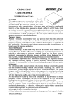
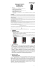
1
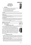
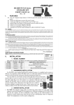
MR-2100/2200 SERIES MAGNETIC STRIPE READER USER’S MANUAL Rev. : Original I. FEATURES Dual directional operation. Convenient operation dual side swipe design (MR-2200). Built-in Magnetic Stripe Reader Triple tracks. Built-in keyboard wedge interface or RS-232 interface or USB interface. Built-in decoder Heavy duty die cast case 3 tracks type MSR can read also AAMVA and CA DMV card FCC NOTICE This equipment generates, uses, and can radiate radio frequency energy and, if not installed and used in accordance with the instructions manual, may cause interference to radio communications. It has been tested and found to comply with limits for a Class A digital device pursuant to subpart J of Part 15 of FCC Rules, which are designed to provide reasonable protection against interference when operated in a commercial environment. Operation of this equipment in a residential area is likely to cause interference in which case the user at his own expense will be required to take whatever measures to correct the interference. WARRANTY LIMITS Warranty will terminate automatically when the equipment is opened by any person other than the authorized technicians. The user should consult his/her dealer for the problem happened. Warranty voids if the user does not follow the instructions in application of this merchandise. The manufacturer is by no means responsible for any damage or hazard caused by improper application. The hardware utility program, including instructions for its use, is provided “AS IS” without warranty of any kind. Posiflex Technology, Inc. further disclaims all implied warranties including without limitation any implied warranties of merchantability or of fitness for a particular purpose. The entire risk arising out of the use or performance of the software and documentation remains with you. ABOUT THIS MANUAL This manual is written in an attempt with full strength to assist the user to utilize the stand-alone magnetic stripe reader MR2100/MR2200 series of Posiflex POS products. This series of products provide excellent flexibility and reliability in application. This manual covers both operational and technical aspects of these units. The manufacturer of the MR2100/2200 series heartily apologizes to the user for reserving the right to change or to modify this manual without notice due to the rapid and constant progress and improvement on science and technology. The user may always obtain the most up to date information through any of our web sites: http://www.posiflex.com or http://www.posiflex.com.tw or http://www.posiflexusa.com. Copyright Posiflex Technology, Inc. 2011 All rights are strictly reserved. No part of this documentation may be reproduced, stored in a retrieval system, or transmitted in any form or by any means, electronic, mechanical, photocopying, or otherwise, without the prior written consent of Posiflex Technology, Inc. the publisher of this documentation TRADE MARKS AND SERVICE MARKS P/N: 19030901010 POSIFLEX is a registered trademark of Posiflex Technology, Inc. an ISO-9001 and ISO-14001 certified manufacturer. Other brand and product names are trademarks and registered trademarks and service marks of their respective owners. II. MODEL IDENTIFICATIONS Models MR2100 Application Interface USB or RS232 or PS2 Reader Head ISO Single Head III. 警告使用者 T31454 這是甲類的資訊產品,在居住的環 境中使用時,可能會造成射頻干 擾,在這種情況下,使用者會被要 求採取某些適當的對策。 MR2100-JIS2 MR2200 USB or RS232 JIS2 USB or RS232 or PS2 ISO Dual Side Head SPECIFICATIONS Reader specification ISO 7811 JIS X 6302 Applicable card type Card feed method Manual Card feed direction Bi-direction Read / write function Read only Card feed speed 5 to 55 inches/sec. 100 ~ 1200 mm/sec. Error rate Less than 0.5% Less than 0.1% Card data format Data standard IATA ABA THRIFT JIS I JIS II Track used Track 1 Track 2 Track 3 (Track 2) Rear side Applicable to MR2100-MR2200 MR2100-JIS2 models 2 Recording method F F (FM) Recording density 210 BPI 75 BPI 210 BPI 75 BPI 210 BPI Recording capacity 79 / 7 40 / 5 107 / 5 40 / 5 72 / 7 characters / bits Note: AAMVA and CA DMV standards are supported in 3 track ISO models Dimensions: 14.5 cm (L) X 4.6 cm (W) X 3.4 cm (H) Weight: 490 gm LED: dual color -- green for good read or ready to read red for invalid read Rated voltage: 5 VDC Rated current: 100 mA max. Page 1 / 2 IV. CABLE CONNECTION GUIDE Cable connection for KB WEDGE models MR2100/MR2200 PC KB I/P Mini DIN 6 P Male PC Keyboard Mini DIN 6 P Female Cable connection for RS232 interface models MR2100/MR2200 2.5/5.5 DC plug from power adaptor D sub 9 P Female to COM port Cable connection for USB interface models PC USB port or USB hub V. MR2100/MR2200 ADJUSTABLE PARAMETERS Some parameters in readout format of the MR2100/MR2200 series in PS/2 KB interface and USB interface can be controlled by software downloaded from our web site: http://www.posiflex.com. However, PS/2 and USB model are automatically saved parameters even after power off and on. It is also possible to adjust some parameters with modification in hardware described below if not by software. Please note that the individual track enable mentioned applies only when the track is supported in physical reader head. For ISO & JIS2 in USB Mode Jumper Setting (1). P2 : Connected to USB Cable (2). CN3 : ISP(Update MCU Firmware) (3). CN4 / CN5 : ISO Magnetic Stripe Reader (Use in "USB KB mode" or HID mode") (4). CN4 / CN5 : JIS2 Magnetic Stripe Reader (Only use in "USB KB mode") Jumper Setting: Jumper Position J1 Function ALT-Num NumLock Opened Enable Send Numlock Key Code Closed Disable N/A Default Close Close J2 J3 J4 USB Class Boot protocol Vendor Class for Linux Boot protocol for DOS or WinCE 6.22 Non-Boot protocol for HID Class for Windows Windows Close Close For ISO in PS2 & RS232 Mode Jumper Setting For RS232 Mode: (1). P1 : Not connected. (2). P2 : Cable Connected to MB(Com Port) & Power: 5V. (3). CN3 : ISP(Update MCU Firmware) (4). CN4/CN5: ISO Magnetic Stripe Reader/JIS2 Jumper Setting: Jumper Function J1 Alt-Num Opened Enable J2 Lead/ End Code Enable Closed Disable Disable Default J3 PS2/ RS232 PS2 J4 Trk1 J5 Trk2 J6 Trk3 JP1 Header2x2 RS232 JP2 Header2x2 PS2 Disable Disable Disable RS232 Enable Enable Enable CLOSE OPEN J6 PS2 Pin Switch JP1 Header2x2 RS232 JP2 Header2x2 PS2 OPEN OPEN CLOSE CLOSE Note: RS232 Mode must be closed J3, JP1; Opened JP2. For PS2 Mode: (1). P1 : Connected to PC(PS2-KB Port) (2). P2 : Connected to Keyboard (3). CN3: ISP (Update MCU Firmware) (4). CN4/CN5: ISO Magnetic Stripe Reader Jumper Setting: Jumper Function Opened Enable J2 Lead/ End Code Enable Closed Disable Disable Default J1 Alt-Num J3 PS2/ RS232 PS2 J4 Reserve J5 Reserve RS232 OPEN Note: PS2 Mode must be opened J3, J6, JP1; closed JP2 Page 2 / 2