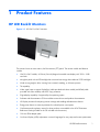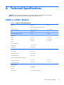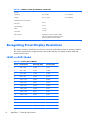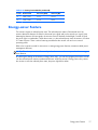
1
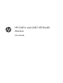
HP L2401x and x2401 LED Backlit
Monitors
User Guide
© 2012, Hewlett-Packard Development
Company, L.P.
The only warranties for HP products and
services are set forth in the express warranty
statements accompanying such products and
services. Nothing herein should be
construed as constituting an additional
warranty. HP shall not be liable for technical
or editorial errors or omissions contained
herein.
This document contains proprietary
information that is protected by copyright.
No part of this document may be
photocopied, reproduced, or translated to
another language without the prior written
consent of Hewlett-Packard Company.
First Edition (September 2012)
Document Part Number: 701303–001
About This Guide
This guide provides information on setting up the monitor, installing the VESA adapter plate, contacting
HP support, and technical specifications.
WARNING! Text set off in this manner indicates that failure to follow directions could result in bodily
harm or loss of life.
CAUTION: Text set off in this manner indicates that failure to follow directions could result in damage
to equipment or loss of information.
NOTE: Text set off in this manner provides important supplemental information.
iii
iv
About This Guide
Table of contents
1 Product Features ............................................................................................................... 1
HP LED Backlit Monitors ............................................................................................................ 1
2 Setting Up the Monitor ...................................................................................................... 2
Extending the Monitor Stand ..................................................................................................... 2
Side connectors ....................................................................................................................... 3
Connecting the Cables ............................................................................................................. 4
Front Panel Controls ................................................................................................................. 5
Adjusting the Tilt ...................................................................................................................... 6
VESA Adapter Plate ................................................................................................................. 6
What You Need ....................................................................................................... 6
Safety Information ..................................................................................................... 7
Removing the Stand from the Monitor .......................................................................... 7
Installing the VESA Adapter Plate onto the Monitor ........................................................ 9
Removing the VESA Adapter Plate ............................................................................. 10
Replacing the Stand ................................................................................................ 12
Turning on the Monitor ........................................................................................................... 13
Locating the Rating Label ........................................................................................................ 13
3 Finding More Information ............................................................................................... 14
Product Support ..................................................................................................................... 14
Appendix A Technical Specifications ................................................................................... 15
L2401x/x2401 Models .......................................................................................................... 15
Recognizing Preset Display Resolutions ..................................................................................... 16
L2401x/x2401 Model ............................................................................................ 16
Energy-saver Feature .............................................................................................................. 17
v
vi
1
Product Features
HP LED Backlit Monitors
Figure 1-1 HP L2401x/x2401 Monitors
The monitors have an active matrix, thin-film transistor (TFT) panel. The monitor models and features
include:
●
L2401x/x2401 models, 60.96-cm (24-inch) diagonal viewable area display with 1920 x 1080
resolution
●
Non-glare panel with an LED backlight that consumes less energy than traditional CCFL backlights
●
Wide viewing angle to allow viewing from a seated, standing, or off-center position
●
Tilt capability
●
Video signal input to support DisplayPort (cable provided with select models) and HDMI (cable
provided with select models) with HDCP copy protection
●
Plug-and-play capability if supported by the operating system
●
Software and documentation CD that includes monitor drivers and product documentation
●
HP Display Assistant for adjusting monitor settings and enabling theft-deterrence feature
●
Energy-saver feature to meet requirements for reduced power consumption
●
Certifications and regulatory notices for these products are available in the HP LCD Monitors
Reference Guide (provided on the CD included with the monitor)
●
100 mm VESA adapter plate
●
On-Screen Display (OSD) adjustments in several languages for easy setup and screen optimization
HP LED Backlit Monitors
1
2
Setting Up the Monitor
To set up the monitor, ensure that the power is turned off to the monitor, computer system, and other
attached devices, and then follow the instructions below.
Extending the Monitor Stand
1.
Lift the monitor from its box and place it face down on a flat surface.
2.
Grasp the stand and pull upward until fully extended.
CAUTION: Do not touch the surface of the panel. Pressure on the panel may cause permanent
non-uniformity of color or disorientation of the liquid crystals.
Figure 2-1 Extending the monitor stand
3.
2
Place the monitor in an upright position on a flat surface so that the feet are touching the surface.
Press down firmly on the top center area of the monitor to ensure that the monitor is stable.
Chapter 2 Setting Up the Monitor
Side connectors
Figure 2-2 Side connectors
Table 2-1 Side connectors
Connector
Function
1
DisplayPort
Connects the DisplayPort video cable (provided with select
models) from the computer to the monitor
2
HDMI
Connects the HDMI video cable (provided with select
models) from the computer to the monitor
3
DC Power Jack
Connects the external power adapter to the monitor
Side connectors
3
Connecting the Cables
1.
Place the monitor in a convenient, well-ventilated location near the computer.
Figure 2-3 Connecting the monitor
2.
Connect one end of the DisplayPort signal cable (provided with select models) to the DisplayPort
connector on the side of the monitor and the other end to the DisplayPort connector on the
computer.
3.
Connect one end of the HDMI signal cable (provided with select models) to the HDMI connector
on the side of the monitor and the other end to the HDMI connector on the computer.
4.
Connect the power adapter cord to the power connector on the side of the monitor. Connect one
end of the power cord to the power supply brick and the other end to an electrical wall outlet.
WARNING!
To reduce the risk of electric shock or damage to the equipment:
Do not disable the power cord grounding plug. The grounding plug is an important safety feature.
Plug the power cord into a grounded (earthed) electrical outlet that is easily accessible at all times.
Disconnect power from the equipment by unplugging the power cord from the electrical outlet.
For your safety, do not place anything on power cords or cables. Arrange them so that no one may
accidentally step on or trip over them. Do not pull on a cord or cable. When unplugging from the
electrical outlet, grasp the cord by the plug.
4
Chapter 2 Setting Up the Monitor
Front Panel Controls
Figure 2-4 Monitor front panel controls
Table 2-2 Monitor front panel controls
Control
1
Function
Power LED
Blue = Fully powered.
Amber = Sleep mode.
Off = Off mode.
2
Power
Turns the monitor on or off.
3
Menu
Opens, selects or exits the OSD menu.
4
Minus
Moves the OSD cursor down/decreases the OSD adjustment
level.
5
Plus
Moves the OSD cursor up/increases the OSD adjustment
level.
6
OK
If the OSD menu is on, press to select the highlighted menu
item.
NOTE: To view an OSD menu simulator, visit the HP Customer Self-Repair Services Media Library at
http://www.hp.com/go/sml.
Front Panel Controls
5
Adjusting the Tilt
Tilt the monitor's panel to set it to a comfortable eye level.
Figure 2-5 Tilting the monitor
VESA Adapter Plate
The monitor includes a VESA 100 mm x 100 mm (3.9 in x 3.9 in) adapter plate. This can be used to
attach the monitor panel to a VESA-compatible device (purchased separately), such as a stand, swing
arm, or other mounting fixture.
What You Need
6
●
A Phillips screwdriver and a flathead screwdriver (magnetic-tipped recommended)
●
A stable flat surface covered with a soft, clean cloth (such as a clean, large towel) to protect the
monitor when you place it face down
●
Another person (it might require two people to lift and move the monitor)
●
Antistatic wrist strap and a conductive foam pad to stand on while attaching the VESA adapter
plate (recommended)
●
VESA device (sold separately) with the following specifications:
◦
VESA standard 100 mm x 100 mm (3.9 in x 3.9 in) hole pattern
◦
Provides at least 58 mm (2.28 inches) space behind the monitor for the monitor power cord
and cables
Chapter 2 Setting Up the Monitor
Safety Information
This product has not been evaluated for connection to an “IT” power system (an AC distribution system
with no direct connection to the earth, according to IEC 60950).
WARNING! Always disconnect the monitor from the power source before lifting, moving, or
removing the stand from your monitor. Failure to do so can result in personal injury or equipment
damage.
Removing the Stand from the Monitor
To avoid injury and equipment damage, always complete the following steps in order:
1.
Turn the monitor off and disconnect the power cord from the wall outlet.
CAUTION: Static electricity can damage the electronic components of the monitor or other
equipment. Ensure that you are discharged of static electricity by briefly touching a grounded
metal object.
2.
Disconnect any equipment and all attached cables from the monitor before beginning this
procedure.
3.
Lay the monitor face down on a flat surface covered by a clean, dry cloth.
4.
Remove the detachable hinge cover.
Figure 2-6 Removing the detachable hinge cover
VESA Adapter Plate
7
5.
Remove the four screws from the monitor stand.
Figure 2-7 Removing the screws from the monitor stand
Save the monitor stand and the four screws, in the event that you decide to convert your monitor back
to a desktop monitor in the future.
8
Chapter 2 Setting Up the Monitor
Installing the VESA Adapter Plate onto the Monitor
NOTE: This apparatus is intended to be supported by a UL or CSA Listed wall-mount bracket.
1.
Remove the stand from the monitor panel. Refer to Removing the Stand from the Monitor
on page 7.
2.
Install the VESA adapter plate that shipped with the monitor.
a.
With the monitor face down on the table, slide the VESA adapter plate from the lower edge
of the monitor toward the bracket hinge until the VESA adapter plate is in position over the
bracket hinge.
Figure 2-8 Positioning the VESA adapter plate
VESA Adapter Plate
9
b.
Secure the lower edge of the VESA adapter plate to the bracket hinge with four screws.
Figure 2-9 Securing the VESA adapter plate
3.
To attach the monitor to a VESA-compatible device (purchased separately), follow the instructions
included with that device to ensure that the monitor is safely attached.
CAUTION: This monitor supports the VESA industry-standard 100 mm mounting holes. To attach
a third-party solution to the monitor, four 4 mm, 0.7 pitch, and 10 mm long screws (purchased
separately) are required. Longer screws must not be used because they may damage the monitor.
It is important to verify that the manufacturer’s solution is compliant with the VESA standard and is
rated to support the weight of the monitor display panel. For best performance, it is important to
use the power and video cables provided with the monitor.
4.
Reconnect the cables to the monitor panel.
Removing the VESA Adapter Plate
To avoid injury and equipment damage, always complete the following steps in order:
1.
Turn the monitor off and disconnect the power cord from the wall outlet.
CAUTION: Static electricity can damage the electronic components of the monitor or other
equipment. Ensure that you are discharged of static electricity by briefly touching a grounded
metal object.
10
2.
Disconnect any equipment and all attached cables from the monitor before beginning this
procedure.
3.
To remove the monitor from a mounting device, follow the instructions included with that device to
safely detach the monitor and remove any mounting hardware.
Chapter 2 Setting Up the Monitor
4.
Remove the four screws securing the lower edge of the VESA adapter plate to the bracket hinge.
Figure 2-10 Removing the screws securing the VESA adapter plate
5.
Slide the VESA adapter plate toward the lower edge of the monitor and off the bracket hinge.
Figure 2-11 Removing the VESA adapter plate
VESA Adapter Plate
11
Replacing the Stand
1.
Align the monitor stand over the bracket hinge and secure it with the four screws.
Figure 2-12 Securing the monitor stand
2.
Attach the hinge cover.
Figure 2-13 Attaching the stand hinge cover
12
Chapter 2 Setting Up the Monitor
Turning on the Monitor
1.
Press the power button on the front of the monitor to turn it on.
2.
Press the power button on the computer to turn it on.
CAUTION: Burn-in image damage may occur on monitors that display the same static image on the
screen for a prolonged period of time (12 or more consecutive hours of non-use). To avoid burn-in
image damage on the monitor screen, you should always activate a screen saver application or turn off
the monitor when it is not in use for a prolonged period of time. Image retention is a condition that may
occur on all LCD screens. Monitors with a burned-in image are not covered under the HP warranty.
When the monitor is powered on, the power LED on the front of the monitor is blue.
Locating the Rating Label
The rating label on the monitor provides the spare part number, product number, and serial number.
You may need these numbers when contacting HP about the monitor model. The rating label is located
on the rear panel of the monitor.
Figure 2-14 Locating the rating labels
Turning on the Monitor
13
3
Finding More Information
Refer to the HP LCD Monitors Reference Guide included on the CD with your monitor for additional
information on:
●
Optimizing monitor performance
●
Safety and maintenance guidelines
●
Installing software from the CD
●
Using the OSD menu
●
Downloading software from the Web
●
Agency regulatory information
●
Troubleshooting and recommended solutions to common problems
For information on theft deterrence, refer to the HP Display Assistant User Guide included on the CD
that shipped with your monitor.
Product Support
For additional information on using and adjusting your monitor, go to http://www.hp.com/support.
Select your country or region, select Product Support & Troubleshooting, and then enter your
monitor model in the SEARCH window.
NOTE: The monitor user guide, reference guide, and drivers are available at http://www.hp.com/
support.
If the information provided in the guide or in the HP LCD Monitors Reference Guide does not address
your questions, you can contact support. For U.S. support, go to http://www.hp.com/go/contactHP.
For worldwide support, go to http://welcome.hp.com/country/us/en/wwcontact_us.html.
Here you can:
●
Chat online with an HP technician
NOTE: When support chat is not available in a particular language, it is available in English.
14
●
E-mail support
●
Find support telephone numbers
●
Locate an HP service center
Chapter 3 Finding More Information
A
Technical Specifications
NOTE: All specifications represent the typical specifications provided by HP component
manufacturers; actual performance may vary either higher or lower.
L2401x/x2401 Models
Table A-1 L2401x/x2401 Specifications
Display
60.96 cm
24 in
Type
MVA (Multi-domain Vertical Alignment
Viewable Image Size
60.96 cm diagonal
Tilt
10° to 35°
Maximum Weight (Unpacked)
3.3 kg
7.32 lbs
Height
43.13 cm
16.98 inches
Width
56.69 cm
22.32 inches
Depth
13.09 cm
5.15 inches
24 in diagonal
Dimensions:
Graphic Resolution:
Native Mode
1920 x 1080
Safe Mode
640 x 480
Dot Pitch
0.277 (H) x 0.277 (W) mm
Pixels Per Inch
91.79 PPI
Horizontal Frequency
24 to 94 kHz
Vertical Refresh Rate
50 to 76 Hz
Environmental Requirements Temperature:
Operating Temperature
5 to 35° C
41 to 95° F
Storage Temperature
-20 to 60° C
-4 to 140° F
Relative Humidity:
Operating
20% to 80%
Storage
5% to 95%
Power Source
100 – 240 VAC 50/60 Hz
L2401x/x2401 Models
15
Table A-1 L2401x/x2401 Specifications (continued)
Altitude:
Operating
0 to 5,000 m
0 to 16,400 ft
Storage
0 to 12,192 m
0 to 40,000 ft
Measured Power Consumption:
Full Power
28 W
Typical Settings
23 W
Sleep
<0.5 W
Switch Off
<0.5 W
Input Terminal
DisplayPort connector (cable included
with select models) and HDMI connector
(cable included with select models)
Recognizing Preset Display Resolutions
The display resolutions listed below are the most commonly used modes and are set as factory defaults.
This monitor automatically recognizes these preset modes and they will appear properly sized and
centered on the screen.
L2401x/x2401 Model
Table A-2 Factory Preset Modes
16
Preset
Pixel Format
Horz Freq (kHz)
Vert Freq (Hz)
1
640 × 480
31.469
59.94
2
640 × 480
37.861
72.809
3
720 × 400
31.469
70.087
4
800 × 600
37.879
60.317
5
1024 × 768
48.363
60.004
6
1280 × 720
45.00
59.94
7
1280 × 768
47.396
59.995
8
1280 × 800
49.702
59.81
9
1280 × 960
60.00
60.00
10
1280 × 1024
63.981
60.02
11
1366 × 768
47.712
59.79
12
1600 × 900
60.00
60.00
13
1600 × 1000
61.648
60.00
14
1600 × 1200
75.00
60.00
Appendix A Technical Specifications
Table A-2 Factory Preset Modes (continued)
Preset
Pixel Format
Horz Freq (kHz)
Vert Freq (Hz)
15
1680 × 1050
65.29
59.954
16
1920 × 1080
67.50
60.00
Energy-saver Feature
The monitors support a reduced power state. The reduced power state will be entered into if the
monitor detects the absence of either the horizontal sync signal and/or the vertical sync signal. Upon
detecting the absence of these signals, the monitor screen is blanked, the backlight is turned off, and
the power light is turned amber. When the monitor is in the reduced power state, the monitor will utilize
0.5 watts of power. There is a brief warmup period before the monitor will return to its normal
operating mode.
Refer to the computer manual for instructions on setting energy-saver features (sometimes called powermanagement features).
NOTE: The above power-saver feature only works when connected to computers that have energysaver features.
By selecting the settings in the monitor's Energy Saver utility, you can also program the monitor to enter
into the reduced power state at a predetermined time. When the monitor's Energy Saver utility causes
the monitor to enter the reduced power state, the power light blinks amber.
Energy-saver Feature
17