1
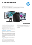
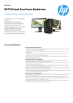
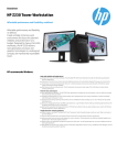
Rugged, Reliable, Mobile, Secure
TM
Data Express DX115 DC SAS/SATA Install Guide
Removable SAS/SATA Drive Enclosure
NOTE: For SAS operation, a SAS controller and SAS hard drive are
required.
SAS DX115 DC receiving frame supports SAS and SATA drives. SATA
6Gb/s DX115 DC receiving frame supports SATA drives only.
Package Contents
(1) DX115 DC Receiving Frame and/or Drive Carrier
(4) M3 drive mounting screws for 2.5” drives
(4) #6-32 drive mounting screws for 3.5” drives
(4) M3 chassis mounting screws
(1) Power Adapter- Legacy 4pin to 15pin SATA
Carrier
Handle
Push Here to Eject Carrier
* If the Power Button is enabled use the Power Button will function as
follows:
Drive Ready/
Error LED
Drive
Activity
LED
OFF - P ress and hold down the power button until the Drive Ready LED
starts to flash. Drive is ready to be removed when the Drive Ready
LED is OFF.
ON* - Press and hold down the power button until the Drive Ready LED
starts to flash. Drive is ready to be accessed when the Drive Ready
LED is ON.
Operation
Power
Button
Fan Error LED
Disable Button
Drive Ready/Error LED
This bi-color LED indicates either the status of the drive or fan/DC
power, depending on the color.
Drive Ready (blue): Flashing blue LED indicates that drive is
inserted and powering up. Steady blue LED glow indicates drive is
powered on and ready for access.
Figure 1: Front Bezel
Carrier Handle
This handle allows the ejection and installation of the drive carrier.
Error (red): Flashing red and blue LED indicates a fan failure.
Steady red LED glow indicates DC power failure.
To eject the carrier, simply push on carrier handle. Once handle pivots
outward, pull handle to remove carrier.
Drive Activity LED
This amber LED indicates when the host computer is accessing the data
on the drive. LED will flash during communication with the host computer.
To install the carrier, simply insert the drive carrier into the receiving
frame. Push handle in to fully seat carrier into the receiving frame.
Power Button
The DX115 DC ships with the power button disabled. To enable the button remove the Power Button Disable jumper (see Figure 2 for details).
CAUTION: It is the responsibility of the user to ensure that the host
does not access the drive while attempting to remove the drive.
Failure to do so may result in loss of data and/or damage to the
drive itself!
Most SAS drives provide support for the Drive Activity LED feature (refer
to your SAS drive manufacturer’s documentation for further information).
If your drive does not support this feature, the Drive Activity LED can
be enabled via host connection (cable not included) to Pin 1 located on
Receiving Frame Motherboard (Figure 2). Refer to your SAS PC system/
host controller manufacturer’s documentation for further information.
1-800-260-9800
www.CRU-DataPort.com
Rugged, Reliable, Mobile, Secure
TM
Fan Error LED Disable Button
This button allows the user to disable the Fan Error LED (insert a paper
clip or similar object to disable). CRU-DataPort recommends replacing
a faulty fan immediately. Contact CRU-DataPort for spare fan ordering
information.
Power Connector
3.5” Bottom-mount Drive
with Four (4) #6-32
Phillips Flat Head
Screws (Provided)
SAS/SATA
Connector
Drive Carrier
Board
2.5” Bottom-mount Drive
with Four (4) #6-32
Phillips Flat Head
Screws (Provided)
Click-connect plate
Auto
Power
on enable
Cooling
Fan
GND
Host Activity
LED Pin
Reserved
Pins
HDD LED
Activity Disable
Figure 3 - Drive Installation
Limited Product Warranty
Figure 2: DX115 DC SAS Receiving Frame Rear Panel with cable
support bracket removed (SATA receiving frame not shown)
CRU-DataPort (CRU) warrants the Data Express DX115 DC to be free
of significant defects in material and workmanship for a period of five
years from the original date of purchase. CRU’s warranty is nontransferable and is limited to the original purchaser.
Drive Activity LED Pins
Pin 1 can be used for host connection (cable not included) to the Drive
Activity LED (Figure 2) if your drive does not support this feature (refer to
your SAS PC system/host controller manufacturer’s documentation for
further information). For Host Activity LED support instead of Drive Activity LED support remove the HDD activity LED disable jumper.
Limitation of Liability
Cooling Fan
Field-replaceable fan provides ample cooling (4.6 CFM) for drive.
Installation
NOTE: A #1 and #2 Phillips screwdriver will be required during this procedure.
1. Remove the drive cover from the DX115 drive carrier and save the screws.
2. Carefully insert the drive (not included) into the carrier. Slide the drive
towards the Drive Carrier Board, so that the I/O connector on the
drive mates with the connector on the Drive Carrier Board (Figure 3).
Turn the drive/carrier assembly over.
3. Fasten the drive into place using the mounting screws provided
(Figure 3). Some drives may require minor adjustment before securing
into carrier with screws.
4. Install the provided drive cover.
The warranties set forth in this agreement replace all other warranties. CRU
expressly disclaims all other warranties, including but not limited to, the
implied warranties of merchantability and fitness for a particular purpose
and non-infringement of third-party rights with respect to the documentation and hardware. No CRU dealer, agent or employee is authorized to
make any modification, extension, or addition to this warranty. In no event
will CRU or its suppliers be liable for any costs of procurement of substitute products or services, lost profits, loss of information or data, computer
malfunction, or any other special, indirect, consequential, or incidental
damages arising in any way out of the sale of, use of, or inability to use
any CRU product or service, even if CRU has been advised of the possibility
of such damages. In no case shall CRU’s liability exceed the actual money
paid for the products at issue. CRU reserves the right to make modifications
and additions to this product without notice or taking on additional liability.
Certification
EMI Standard:
EMC Standard:
FCC Part 15 Class B, CE CISPR B
EN55022, EN55024
This device has been tested and found to comply with the limits for a
Class B digital device, pursuant to Part 15 of the FCC rules. Operation is
subject to the following two conditions:
1. This device may not cause harmful interference, and
2. This device must accept any interference received; including interference that may cause undesired operation
Register your product at www.CRU-DataPort.com
A7-115-0003 Rev. 3.3
1-800-260-9800
www.CRU-DataPort.com