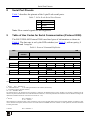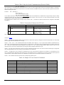
1
Kramer Electronics, Ltd. USER MANUAL Model: VP-14xl RS-232 Port Extender Contents Contents 1 2 2.1 3 4 5 6 6.1 6.2 6.3 6.4 6.5 6.6 7 8 9 Introduction Getting Started Quick Start Overview Defining the VP-14xl RS-232 Port Extender Connecting the VP-14xl RS-232 Port Extender Setting the DIP-switches on the VP-14xl Setting the RS-485 Bus Termination Setting the ADDR DIP-switches Setting the BAUD DIP-switches Selecting Hardware/Software Mode Hardware Mode Software Mode Technical Specifications Serial Port Pinouts Table of Hex Codes for Serial Communication (Protocol 2000) 1 1 1 3 4 5 6 6 7 7 7 8 8 8 9 9 Figures Figure 1: VP-14xl RS-232 Port Extender Front and Rear Panels Figure 2: Connecting the VP-14xl RS-232 Port Extender Figure 3: VP-14xl DIP-switches 4 5 6 Tables Table 1: VP-14xl RS-232 Port Extender Front and Rear Panel Features Table 2: VP-14xl DIP-switch Functions Table 3: Hardware Mode Reply Source DIP-switch Setting Table 4: Software Mode RS-485 Machine Number DIP-switch Setting Table 5: Serial Port Baud Rate DIP-switch Setting Table 6: Technical Specifications of the VP-14xl RS-232 Port Extender Table 7: 9-Pin D-sub Serial Port Pinouts Table 8: Protocol Command Definition Table 9: Instruction Codes for the VP-14xl Table 10: Sample VP-14xl Control Commands 4 6 7 7 7 8 9 9 10 10 i Introduction 1 Introduction Welcome to Kramer Electronics! Since 1981, Kramer Electronics has been providing a world of unique, creative, and affordable solutions to the vast range of problems that confront the video, audio, presentation, and broadcasting professional on a daily basis. In recent years, we have redesigned and upgraded most of our line, making the best even better! Our 1,000-plus different models now appear in 11 groups 1 that are clearly defined by function. Congratulations on purchasing your Kramer Tools™ VP-14xl RS-232 Port Extender. This product is ideal for: • Converting USB and RS-485 interfaces to RS-232 interfaces • Monitoring several RS-232 controlled machines via one PC port • Inter-communication between several serially controlled machines The package includes the following items: • VP-14xl RS-232 Port Extender • Mounting bracket • Power adapter 2 (5V DC output) • This user manual 3 2 Getting Started We recommend that you: • Unpack the equipment carefully and save the original box and packaging materials for possible future shipment • Review the contents of this user manual • Use Kramer high performance high resolution cables 4 2.1 Quick Start This quick start chart summarizes the basic setup and operation steps. 1 GROUP 1: Distribution Amplifiers; GROUP 2: Switchers and Matrix Switchers; GROUP 3: Control Systems; GROUP 4: Format/Standards Converters; GROUP 5: Range Extenders and Repeaters; GROUP 6: Specialty AV Products; GROUP 7: Scan Converters and Scalers; GROUP 8: Cables and Connectors; GROUP 9: Room Connectivity; GROUP 10: Accessories and Rack Adapters; GROUP 11: Sierra Products 2 As an option, you can purchase the Kramer VA-100P-5 10 Port Universal 5-Volt Power Supply enabling you to supply power to up to 10 Kramer devices that require 5V DC 3 Download up-to-date Kramer user manuals from http://www.kramerelectronics.com 4 The complete list of Kramer cables is available from http://www.kramerelectronics.com 1 Getting Started 2 KRAMER: SIMPLE CREATIVE TECHNOLOGY Overview 3 Overview The unique VP-14xl RS-232 Port Extender distributes an incoming RS-232, RS-485 or USB command as transmitted by a touch screen control system, personal computer or other type of control system, to up to three RS-232 ports. This lets you control up to three compatible devices with only one serial port or RS-232 card. The VP-14xl is specifically designed for use with Kramer switchers and routers, but can be used with any other equipment which employs RS-232. In particular, the VP-14xl features: • One RS-232 input port • One RS-485 input port • One USB input port • Three RS-232 output ports • Operation in either Hardware or Software mode • DIP-switches to determine the source of the reply command when the VP-14xl is in hardware mode • DIP-switches to determine the machine number when operating in Software mode and there are multiple VP-14xl units on the RS-485 bus • DIP-switches to determine the serial port baud rate (see Section 6.3) In Hardware mode, the: • VP-14xl routes the reply from the output port defined by the DIP-switches 2, 3 and 4 (see Section 6.2) • RS-232 data is passed from any input to all outputs In Software mode, the VP-14xl routes the data and reply based on the Protocol 2000 commands received from the PC or other device connected to any of the inputs (RS-232, RS-485 or USB), see Section 8. To achieve the best performance, we recommend: • Connecting only good quality connection cables, thus avoiding interference, deterioration in signal quality due to poor matching, and elevated noise levels (often associated with low quality cables) • Avoiding interference from neighboring electrical appliances that may adversely influence signal quality and positioning your VP-14xl in a location free from moisture and away from excessive sunlight and dust ! Caution: No operator serviceable parts inside the unit Warning: Use only the Kramer Electronics input power wall adapter that is provided with the unit Warning: Disconnect the power and unplug the unit from the wall before installing 3 Defining the VP-14xl RS-232 Port Extender 4 Defining the VP-14xl RS-232 Port Extender Figure 1 and Table 1 define the front and rear panels of the VP-14xl. Figure 1: VP-14xl RS-232 Port Extender Front and Rear Panels Table 1: VP-14xl RS-232 Port Extender Front and Rear Panel Features # 1 2 3 4 5 6 7 8 9 10 11 12 13 4 Feature RS-232 IN 9-pin D-sub (F) Connector RS-485 IN 3-pin Removable Terminal Block USB IN Connector ADDR DIP-switches 2, 3 and 4 Function Connect to source computer 1 Connect to source computer 2. Connect G to the Ground connection, A to the A connection, and B to the B connection Connect to source computer 3 Hardware mode: Determines the reply source Software mode: Determines the machine number (see Section 6.2) BAUD DIP-switches 5, 6 and 7 Determines the serial port baud rate (see Section 6.2) ON LED Lights green when the unit is powered on TERM DIP-switch 1 Sets the RS-485 bus termination (see Section 6.1) S/W DIP-switch 8 Selects Software or Hardware mode (see Section 6.4) Connect to destination or switcher 1 (see Section 8) 1 9-pin D-sub (M) Connectors 2 Connect to destination or switcher 2 RS-232 OUTPUTS 3 3-pin Removable Connect to destination or switcher 3. Connect TX to RX on the Terminal Block destination, RX to TX, and G to Ground RESET Button Press to initiate startup sequence 5V DC Connector Connect to the power adapter, center pin positive KRAMER: SIMPLE CREATIVE TECHNOLOGY Connecting the VP-14xl RS-232 Port Extender 5 Connecting the VP-14xl RS-232 Port Extender Figure 2: Connecting the VP-14xl RS-232 Port Extender To connect your VP-14xl RS-232 Port Extender, as the example in Figure 2 illustrates 1: 1. Connect up to three computer sources to the input connectors (for example, 2 PCs and a laptop). 2. Connect up to three units to be controlled to the output connectors (for example, Kramer switches). 3. If you are using the RS-485 input, set the RS-485 termination (see Section 6.1). 1 Switch OFF the power on each device before connecting it to your VP-14xl. After powering up your VP-14xl, switch on the power to each device 5 Setting the DIP-switches on the VP-14xl 4. Set the Hardware/Software DIP-switch (see Section 6.4) as follows: In Hardware mode, set the REPLY DIP-switches to determine the unique reply output port (see Section 6.2) In Software mode, set the machine number (see Section 6.2). 5. Set the serial port baud rate (see Section 6.3). 6. Select the appropriate machine number (see Section 6.2). 7. Connect the 5V DC power adapter to the 5V DC socket and to the mains electricity. Note: Changing any DIP-switch requires that you either power cycle the VP-14xl or press the Reset button (see Table 1). 6 Setting the DIP-switches on the VP-14xl Moving a DIP-switch down turns the switch on, moving it up turns the switch off. Figure 3: VP-14xl DIP-switches Table 2: VP-14xl DIP-switch Functions DIP-switch # 1 2, 3, 4 5, 6, 7 8 6.1 Function RS-485 termination In Hardware mode: Sets the reply source In Software mode: Sets the machine number Sets the serial port baud rate Sets Software/Hardware mode Setting the RS-485 Bus Termination DIP-switch 1 sets the RS-485 bus termination. Only the first and last physical device on the RS-485 bus must be terminated, all other devices must be unterminated. When the DIP-switch is: • OFF, the unit is un-terminated (default) • ON, the unit is terminated 6 KRAMER: SIMPLE CREATIVE TECHNOLOGY Setting the DIP-switches on the VP-14xl 6.2 Setting the ADDR DIP-switches DIP-switches 2, 3 and 4 set either the reply source (in Hardware mode Table 3) or machine number (in Software mode Table 4). Table 3: Hardware Mode Reply Source DIP-switch Setting Reply Source DIP-switch 2 3 4 Reply is taken from output 1 (default) ON OFF OFF Reply is taken from output 2 OFF ON OFF Reply is taken from output 3 OFF OFF ON Note: When there is more than one VP-14xl attached to the RS-485 bus only one unit can have a reply source set, all other units must have DIP-switches 2, 3 and 4 set to OFF. Table 4: Software Mode RS-485 Machine Number DIP-switch Setting Machine Number 1 2 3 4 DIP-switch 2 3 4 OFF OFF OFF ON OFF OFF OFF ON OFF ON ON OFF Machine Number 5 6 7 8 DIP-switch 2 3 4 OFF OFF ON ON OFF ON OFF ON ON ON ON ON When there is more than one VP-14xl attached to the RS-485 bus each unit must have a unique machine number. 6.3 Setting the BAUD DIP-switches DIP-switches 5, 6 and 7 set the serial port baud rate in both Hardware and Software modes. Table 5: Serial Port Baud Rate DIP-switch Setting Baud Rate 1200 2400 4800 9600 (default) 6.4 DIP-switch 5 6 7 OFF OFF OFF ON OFF OFF OFF ON OFF ON ON OFF Baud Rate 19200 38400 57600 115200 DIP-switch 5 6 7 OFF OFF ON ON OFF ON OFF ON ON ON ON ON Selecting Hardware/Software Mode DIP-switch 8 sets the operating mode to either Hardware or Software mode. When the DIP-switch is: • OFF, the unit is set to Hardware mode (default) • ON, the unit is set to Software mode 7 Technical Specifications 6.5 Hardware Mode In Hardware mode, the: • RS-232 data is passed from any input to all outputs • VP-14xl routes the reply from the output port defined by the DIP-switches 2, 3 and 4 (see Section 6.2). For reliable operation, only one port should be defined 6.6 Software Mode In Software mode, the VP-14xl routes the data and reply based on the Protocol 2000 commands received from the PC or other device connected to any of the inputs (RS-232, RS-485 or USB), see Section 8. Note: Only one reply port can be opened at a time. It is possible to open multiple direct ports but only one reply port can be open at a time. This means that if port1 is currently open and you then open port2, the port 1 is automatically closed. If you then open port 1 again, port 2 is automatically closed. In this way it is possible to close all reply ports, as well as all direct ports. 7 Technical Specifications Table 6 provides the technical specifications for the VP-14xl RS-232 Port Extender. Table 6: Technical Specifications 1 of the VP-14xl RS-232 Port Extender INPUT: OUTPUTS: RS-232 COMPLIANCE OPERATING MODES: USB COMPLIANCE: CONTROLS: POWER SOURCE: OPERATING TEMPERATURE: STORAGE TEMPERATURE: HUMIDITY: DIMENSIONS: WEIGHT: ACCESSORIES: OPTIONS: 1 RS-232 on 9-pin D-sub (F) connector; 1 RS-485 on 3-pin removable terminal block; 1 USB Type B connector 2 RS-232 on 9-pin D-sub (M) connectors, 1 RS-232 on 3-pin removable terminal block 1200 to 115200; 8 data bits, 1 stop bit, no parity Hardware and Software 1.1 DIP-switches 5V DC, 130mA 0° to +55°C (32° to 131°F) -45° to +72°C (-49° to 162°F) 10% to 90%, RHL non-condensing 12cm x 6.9cm x 2.4cm (4.7" x 2.7" x 0.96") W, D, H 0.3kg. (0.7lbs.) approx. 5V DC 2A Power supply, mounting bracket RK-3T 19" rack adapter 1 Specifications are subject to change without notice 8 KRAMER: SIMPLE CREATIVE TECHNOLOGY Serial Port Pinouts 8 Serial Port Pinouts Table 7 describes the pinouts of the 9-pin D-sub serial ports. Table 7: 9-Pin D-sub Serial Port Pinouts Pin 2 3 5 Function Receive Transmit Ground Note: Flow control signals are not supported. 9 Table of Hex Codes for Serial Communication (Protocol 2000) The RS-232/RS-485 Protocol 2000 uses four bytes of information as shown in Table 8. The data rate is set by the DIP-switches (see Table 5), with no parity, 8 data bits and 1 stop bit. Table 8: Protocol Command Definition MSB LSB DESTINATION INSTRUCTION 0 D N5 N4 N3 N2 N1 N0 7 6 5 4 3 2 1 0 1 I6 I5 I4 I3 I2 I1 I0 7 6 5 4 3 2 1 0 1 O6 O5 O4 O3 O2 O1 O0 7 6 5 4 3 2 1 0 1 OVR X M4 M3 M2 M1 M0 7 6 5 4 3 2 1 0 1st byte INPUT 2nd byte OUTPUT 3rd byte MACHINE NUMBER 4th byte Bit 7 – Defined as 0. 1st BYTE: D – “DESTINATION”: 0 - for sending information to the switchers (from the PC); 1 - for sending to the PC (from the switcher). N5…N0 – “INSTRUCTION” The function that is to be performed by the switcher(s) is defined by the INSTRUCTION (6 bits). Similarly, if a function is performed via the machine’s keyboard, then these bits are set with the INSTRUCTION NO., which was performed. The instruction codes are defined according to the table below (INSTRUCTION NO. is the value to be set for N5…N0). 2nd BYTE: Bit 7 – Defined as 1. I6…I0 – “INPUT”. When switching (ie. instruction codes 1 and 2), the INPUT (7 bits) is set as the input number which is to be switched. Similarly, if switching is done via the machine’s front-panel, then these bits are set with the INPUT NUMBER which was switched. For other operations, these bits are defined according to the table. 3rd BYTE: Bit 7 – Defined as 1. 9 Table of Hex Codes for Serial Communication (Protocol 2000) O6…O0 – “OUTPUT”. When switching (ie. instruction codes 1 and 2), the OUTPUT (7 bits) is set as the output number which is to be switched. Similarly, if switching is done via the machine’s front-panel, then these bits are set with the OUTPUT NUMBER which was switched. For other operations, these bits are defined according to the table. 4th BYTE: Bit 7 – Defined as 1. Bit 5 – Don’t care. OVR – Machine number override. M4…M0 – MACHINE NUMBER. Used to address machines in a system via their machine numbers. When several machines are controlled from a single serial port, they are usually configured together with each machine having an individual machine number. If the OVR bit is set, then all machine numbers will accept (implement) the command, and the addressed machine will reply. For a single machine controlled via the serial port, always set M4…M0 = 1, and make sure that the machine itself is configured as MACHINE NUMBER = 1. Table 9: Instruction Codes for the VP-14xl INSTRUCTION # DESCRIPTION DEFINITION FOR SPECIFIC INSTRUCTION INPUT NOTE OUTPUT 2C CONTROLS THE STATUS OF A PORT 0–close 1–open Output bit: O0–O5 = output # or 0 for all outputs O6–0 = Tx; 1 = Rx 1, 2, 4, 5 2D READS THE STATUS OF A PORT 0–open Output bit: O0–O5 = output # O6–0 = Tx; 1 = Rx 2, 3, 4, 5 Note: All values in the table are hexadecimal, unless otherwise stated. NOTES on Table 9: NOTE 1 – When the PC sends this command, if the instruction is valid the unit replies by sending the PC the same 4 bytes that it was sent (except for the first byte where the Destination bit is set high). NOTE 2 – If O6 = 0 (Tx) – This command defines/reads the definition of the output # (1, 2 or3) to pass the RS-232/Direct command from any input. In this case the instruction does not modify previously set output numbers, allowing the setting of multiple outputs for the Direct command. If O6 = 1 (Rx), the command defines/reads the definition of the output # (1, 2 or 3) to pass the reply from the output to inputs. In this case, the instruction resets a previously set output number, preventing the setting of multiple outputs for the reply. NOTE 3 – The reply to this command is as follows: The same command and output codes as were sent are returned, and the input is assigned the value of the parameter that was read. The reply is per the definitions in command 44. NOTE 4 – At initial power-on or on reception of command 44 or 45, any received bytes are analyzed to see whether it is a command 44 or 45. If not, it is transmitted to the output based on the existing setup. If the analyzed bytes are a command 44 or 45, the unit waits for the other 3 bytes and interprets them as a Protocol 2000 command. The command is executed if relevant to this machine number or discarded if not. NOTE 5 – This command works only when the unit is configured for Software mode. Table 10: Sample VP-14xl Control Commands Command 2C 80 80 81 2C 80 C0 81 2C 81 82 81 2C 81 C1 81 2D 80 81 81 2D 80 82 81 2D 80 C1 81 2D 80 C2 81 10 Description Close all output ports for direct command Close all output ports for reply command Open port 2 for direct command Open port 1 for reply command Check status of port 1 for direct command. Port is closed Check status of port 2 for direct command. Port is open Check status of port 1 for reply command. Port is open Check status of port 2 for reply command. Port is closed Reply 6C 80 80 81 6C 80 C0 81 6C 81 82 81 6C 81 C1 81 6D 80 81 81 6D 81 82 81 6D 81 C1 81 6D 80 C2 81 KRAMER: SIMPLE CREATIVE TECHNOLOGY LIMITED WARRANTY We warrant this product free from defects in material and workmanship under the following terms. HOW LONG IS THE WARRANTY Labor and parts are warranted for seven years from the date of the first customer purchase. WHO IS PROTECTED? Only the first purchase customer may enforce this warranty. WHAT IS COVERED AND WHAT IS NOT COVERED Except as below, this warranty covers all defects in material or workmanship in this product. The following are not covered by the warranty: 1. Any product which is not distributed by us or which is not purchased from an authorized Kramer dealer. If you are uncertain as to whether a dealer is authorized, please contact Kramer at one of the agents listed in the Web site www.kramerelectronics.com. 2. Any product, on which the serial number has been defaced, modified or removed, or on which the WARRANTY VOID IF TAMPERED sticker has been torn, reattached, removed or otherwise interfered with. 3. Damage, deterioration or malfunction resulting from: i) Accident, misuse, abuse, neglect, fire, water, lightning or other acts of nature ii) Product modification, or failure to follow instructions supplied with the product iii) Repair or attempted repair by anyone not authorized by Kramer iv) Any shipment of the product (claims must be presented to the carrier) v) Removal or installation of the product vi) Any other cause, which does not relate to a product defect vii) Cartons, equipment enclosures, cables or accessories used in conjunction with the product WHAT WE WILL PAY FOR AND WHAT WE WILL NOT PAY FOR We will pay labor and material expenses for covered items. We will not pay for the following: 1. Removal or installations charges. 2. Costs of initial technical adjustments (set-up), including adjustment of user controls or programming. These costs are the responsibility of the Kramer dealer from whom the product was purchased. 3. Shipping charges. HOW YOU CAN GET WARRANTY SERVICE 1. To obtain service on you product, you must take or ship it prepaid to any authorized Kramer service center. 2. Whenever warranty service is required, the original dated invoice (or a copy) must be presented as proof of warranty coverage, and should be included in any shipment of the product. Please also include in any mailing a contact name, company, address, and a description of the problem(s). 3. For the name of the nearest Kramer authorized service center, consult your authorized dealer. LIMITATION OF IMPLIED WARRANTIES All implied warranties, including warranties of merchantability and fitness for a particular purpose, are limited in duration to the length of this warranty. EXCLUSION OF DAMAGES The liability of Kramer for any effective products is limited to the repair or replacement of the product at our option. Kramer shall not be liable for: 1. Damage to other property caused by defects in this product, damages based upon inconvenience, loss of use of the product, loss of time, commercial loss; or: 2. Any other damages, whether incidental, consequential or otherwise. Some countries may not allow limitations on how long an implied warranty lasts and/or do not allow the exclusion or limitation of incidental or consequential damages, so the above limitations and exclusions may not apply to you. This warranty gives you specific legal rights, and you may also have other rights, which vary from place to place. NOTE : All products returned to Kramer for service must have prior approval. This may be obtained from your dealer. This equipment has been tested to determine compliance with the requirements of: EN-50081: EN-50082: CFR-47: "Electromagnetic compatibility (EMC); generic emission standard. Part 1: Residential, commercial and light industry" "Electromagnetic compatibility (EMC) generic immunity standard. Part 1: Residential, commercial and light industry environment". FCC* Rules and Regulations: Part 15: “Radio frequency devices Subpart B Unintentional radiators” CAUTION! Servicing the machines can only be done by an authorized Kramer technician. Any user who makes changes or modifications to the unit without the expressed approval of the manufacturer will void user authority to operate the equipment. Use the supplied DC power supply to feed power to the machine. Please use recommended interconnection cables to connect the machine to other components. * FCC and CE approved using STP cable (for twisted pair products) 1 For the latest information on our products and a list of Kramer distributors visit www.kramerelectronics.com where updates to this user manual may be found. We welcome your questions, comments, and feedback. Safety Warning: Disconnect the unit from the power supply before opening/servicing. Caution Kramer Electronics, Ltd. Web site: www.kramerelectronics.com E-mail: [email protected] P/N: 2900-000609 REV 2