1
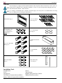
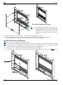
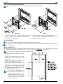
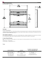
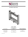
Installation Instructions
INW-AM325
In-Wall Mount
NORTH AMERICA
3130 E. Miraloma Ave.
Anaheim, CA 92806 USA
USA and Canada Phone: 800-368-9700
Fax: 800-832-4888
www.mounts.com
9534-000-011-00
EUROPE
Swallow House,
Shilton Industrial Estate,
Shilton, Coventry, England
CV79JY
Phone: +44 (0) 2476 614700
Fax: +44 (0) 2476 614710
AUSTRALIA, NEW ZEALAND,
OCEANIA (DISTRIBUTOR)
P.O. Box 295
Mordialloc Victoria 3195
Australia
Phone: 03 9586 6330
www.premiermounts.com.au
INW-AM325
TABLE OF CONTENTS
Warning Statements
Parts List
Installation Tools
Mount Location
Wall Cut-Out
Attaching the INW-AM325
Side Cover Installation
In-Wall Electrical Box Installation
AM3/AM3-B and AM250 Installation
Final Installation
Technical Specifications
Warranty
Contact Premier Mounts
Notes
3
4
4
5
5
6
6
6
7
7
8
8
8
8
ELECTRICAL SHOCK HAZARD!! Cutting or drilling into electrical wires and
cables can cause DEATH or SERIOUS PERSONAL INJURY! Always make
certain the area behind the mounting surfaces is free of electrical wires and
cables before cutting, drilling, or installing the in-wall box
EXPLOSION AND FIRE HAZARD! Cutting or drilling into gas plumbing can
cause DEATH or SERIOUS PERSONAL INJURY! Always make certain the
area behind the mounting surface is free of gas, water, waste, or any other
plumbing before cutting, drilling, or installing the in-wall box.
STRUCTURAL FAILURE HAZARD! Ensure removal of center stud will not
cause unacceptable loss of structural strength. Consult a qualified building
contractor and applicable building codes. Failure to take adequate precautions
can cause DEATH or SERIOUS PERSONAL INJURY!
Page 2
Installation Instructions
INW-AM325
Warning Statements
THE WALL STRUCTURE MUST BE CAPABLE OF SUPPORTING AT LEAST A MINIMUM
WEIGHT OF 250 LBS. IF NOT, THE WALL MUST BE REINFORCED. PROPER INSTALLATION
PROCEDURE BY A QUALIFIED SERVICE TECHNICIAN, AS OUTLINED IN THE INSTALLATION
INSTRUCTIONS, MUST BE ADHERED TO. FAILURE TO DO SO COULD RESULT IN SERIOUS
PERSONAL INJURY, OR EVEN DEATH.
SAFETY MEASURES MUST BE PRACTICED AT ALL TIMES DURING THE INSTALLATION OF
THIS PRODUCT. USE PROPER SAFETY GEAR AND TOOLS FOR THE INSTALLATION
PROCEDURE TO PREVENT PERSONAL INJURY.
PRIOR TO THE INSTALLATION OF THIS PRODUCT, THE INSTALLATION INSTRUCTIONS
SHOULD BE READ AND COMPLETELY UNDERSTOOD. THE INSTALLATION INSTRUCTIONS
MUST BE READ TO PREVENT PERSONAL INJURY AND PROPERTY DAMAGE. KEEP THESE
INSTALLATION INSTRUCTIONS IN AN EASILY ACCESSIBLE LOCATION FOR FUTURE
REFERENCE.
Indicates that the power plug is to be disconnected from the power outlet.
Safety precautions must be taken at all times.
Warning and Caution statements.
A secure structure must support the weight, or load, of the display. When mounting to a wall that contains
wooden studs, dead center of the wooden stud must be confirmed prior to installation.
Do not install on a structure that is prone to vibration, movement or chance of impact. Failure to do so could result
in damage to the display and/or damage to the mounting surface.
Do not install near heater, fireplace, direct sunlight, air conditioning or any other source of direct heat energy. Failure
to do so may result in damage to the display and could increase the risk of fire.
At least two qualified people should perform the installation procedure. Injury and/or damage can result from dropping or mishandling the display.
Recommended mounting surfaces: wooden studs and solid-flat concrete. If the mount is to be installed on any surface other than wooden studs, use suitable hardware (which is commercially available).
Contact Premier Mounts with any technical/ installation questions.
Installation Instructions
Page 3
INW-AM325
Parts List
This mounting box is shipped with all installation hardware and components. Make sure that none of these parts are
missing and/or damaged before beginning installation. If there are parts missing and/or damaged, please stop
and contact Premier Mounts - (800) 368-9700.
It is strongly recommended that a licensed electrician supply wire and power to the INW-AM325. Pre-wiring
must be complete prior to installing the INW-AM325.
INW-AM325 (Qty 1)
6-32 x 1/2” Phillips
Screws (Qty 6) - For
use with electrical
box installation (see
NOTE above)
#14 x 1-1/4”Wood
Screws (Qty 20)
1/16” Clear Bumper
Pad (Qty 4)
In-Wall Electrical Box
(Qty 1)
5/16 x 1/2” Hex Head
Bolt (Qty 8)
1/4” Wood Shims
(Qty14)
Split Lock Washer
(Qty 8)
Installation Tools
Portable Drill
Level
Drywall Saw
Stud Finder (Commercially Available)
Rubber Mallet (Commercially Available)
Page 4
INW-AM325 Side
Covers (Qty 2)
Pencil
Tape Measure
Ratchet with 14mm Drive Socket
Phillips Head Screwdriver
Installation Instructions
INW-AM325
Mount Location
Always make certain the area behind the mounting surface is free of electrical wires, cables, and pipes before
cutting, drilling, or installing the mounting screws.
It is strongly recommended that a licensed electrician supply wire and power to the in-wall mounting box. Prior to
intsalling the INW-AM325, please complete all wiring and allow for the appropriate amount of slack.
Wall Cut-Out
1. Determine where the location of the mount/display will
be.
While installing the INW-AM325, you will
possibly come into contact with electrical
wires, plumbing, and insulation. Take the
necessary precautions before proceeding
with this installation.
2. Use a stud finder (commercially available) to locate the
wood studs that will be used for the installation. Mark
the stud locations with a pencil.
3. Center and level the INW-AM325 between the
marked studs. Using the INW-AM325 as a template,
draw a pencil line completely around the housing.
4. Cut the drywall on the outside edge of the line and
remove the drywall. Make sure that the cut is flush and
even with the vertical wall stud.
Use a saw to cut out the center stud.
5. Remove the center stud, making sure beforehand that
the center stud is not still attached to the opposite wall.
Installation Instructions
Attaching the INW-AM325
All existing wires must be moved and anchored to
either side of the mounting area (attach in a corner
where the wood stud and the rear wall surface
connect).
1. Place the INW-AM325 in the opening.
2. Place six (6) 1/4” wood shims on each side of the
INW-AM325 (between the INW-AM325 and the wood stud).
3. Insert the sixteen (16) #14 x 1-1/4” wood screws into the
mounting points. Do not overtighten these screws.
The wood shims must be placed between the wood
stud and the INW-AM325. Please refer to the
figure above for correct placement of the wood
shims. Use wood shims as required.
The purpose of the wood shims is to help center the
unit, as well as provide a tight fit when all the wood
screws are tightened down. Use as many shims as
it takes to ensure that the box is level and centered.
4. Once the wood shims are inserted, tighten down all of the
wood screws.
Page 5
INW-AM325
Side Cover Installation
INW-AM325 Installation Complete
When attaching the side covers, make sure that the
1/4” wood shims are in line with the side cover
mounting holes. If the wood shims split while
attaching the wood screw, don't panic. These wood
shims have been designed to split in half to cover
more area.
1. To attach the side covers, use four (4) #14 x 1-1/4” wood screws to attach the side covers.
2. Line up the mounting holes on the side covers with the mounting holes that are located on the INW-AM325.
3. Once the mounting holes are aligned, insert the four (4) #14 x 1-1/4” wood screws and tighten.
In-Wall Electrical Box Installation
It is best to have a professional install this product.
It is strongly recommended that a licensed electrician be hired to supply wire and power to the in-wall mount. Wiring
must be ran prior to installing the INW-AM325. The cutout in the mounting box is sized to accommodate a standard
RACO junction box. Route all audio/ visual cables and power wires through the cutouts.
1. Use two (2) 6-32 x 1/2” Phillips screws to attach the electrical box to the mounting box.
2. The remaining 6-32 x 1/2” Phillips screws will be used to attach the electrical outlet to the electrical box (see NOTE above).
Page 6
Installation Instructions
INW-AM325
AM3/AM3-B and AM250 Installation
See the AM3/AM3-B and AM250 Installation Instructions for further instructions.
AM3/AM3-B
AM250
1. Use eight (8) 5/16” X 1/2” hex head bolts and eight (8) lock 1. Use four (4) 5/16” X 1/2” hex head bolts and four (4) lock
washers to attach the AM250 to the INW-AM325.
washers to attach the AM3 / AM3-B to the INW-AM325.
2. Tighten using a socket wrench.
2. Tighten using a socket wrench.
Final Installation
See the AM3/AM3-B and AM250 Installation Manuals for further instructions.
Place four (4) 1/16” clear bumpers on the mount where the mount comes into contact with either the wall surface or the
INW-AM325.
Special Applications
The following instructions cover special applications. If the stud spacing is more than 16” (i.e. 18”, or stud location), the wall must
be re-inforced. The illustration below will cover how this is done. All previous WARNING: statements apply.
It is best to have a qualified professional install this product.
1. Measure from the wood stud to the edge of the
in-wall box.
2. To make up the distance from the edge of the
in-wall box to the wood stud, spacer boards
must be used.
3. Attach the first spacer board using
commercially available 3” wood screws.
4. Re-measure the distance from the spacer board
to the edge of the in-wall box. If the distance is
greater than 2.5”, attach another spacer board.
5. Please use the supplied wood shims to finish
the installation of the in-wall box (please refer
to Attaching the INW-AM325, page 5).
It is strongly recommended that the
AM3 pivot point (the side the arm is
attached to) be mounted on the
side that DOES NOT have the spacer
boards. The AM3 should be
mounted as tightly as possible against
the wooden wall stud.
Installation Instructions
Page 7
INW-AM325
Technical Specifications
All measurements in inches/(mm).
Warranty
Limited Lifetime Warranty
All Premier Mounts products carry a limited lifetime warranty from ship date against defects in materials and workmanship. Premier Mounts is
not liable for improper installation that results in damage to mounts, adapters, display equipment or personal injury. Any modification to the existing mount will void the manufacturers' warranty.
DISCLAIMER OF WARRANTY.
THE FOREGOING WARRANTY IS IN LIEU OF ALL OTHER WARRANTIES, EXPRESS OR IMPLIED, INCLUDING BUT NOT LIMITED TO THE IMPLIED WARRANTIES OF MERCHANTABILITY AND FITNESS FOR A PARTICULAR PURPOSE.
Contact Premier Mounts
In the event of missing and/or damage equipment, or technical questions, the following information can help in the completion of the installation.
Customer Service - (800) 368-9700
Technical Support - [email protected]
Notes
NORTH AMERICA
3130 E. Miraloma Ave.
Anaheim, CA 92806 USA
USA and Canada Phone: 800-368-9700
Fax: 800-832-4888
www.mounts.com
Page 8
EUROPE
Swallow House,
Shilton Industrial Estate,
Shilton, Coventry, England
CV79JY
Phone: +44 (0) 2476 614700
Fax: +44 (0) 2476 614710
AUSTRALIA, NEW ZEALAND,
OCEANIA (DISTRIBUTOR)
P.O. Box 295
Mordialloc Victoria 3195
Australia
Phone: 03 9586 6330
www.premiermounts.com.au
Installation Instructions