1
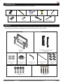
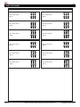
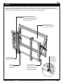
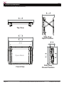
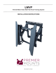
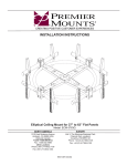
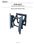
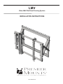
LMV
Video Wall Flat-Panel Framing System
INSTALLATION INSTRUCTIONS
9541-000-001-00
LMV
Contents
Weight Limit............................................................................................................................................................... 2
Warning Statements.................................................................................................................................................. 2
Installation Tools........................................................................................................................................................ 3
Parts List................................................................................................................................................................... 3
Features.................................................................................................................................................................... 5
Installing the Wall Plate............................................................................................................................................. 6
Introduction................................................................................................................................................... 6
Installing Optional Model Specific Spacers............................................................................................................... 8
Installing the Mounting Brackets............................................................................................................................... 9
Selecting the Mounting Hardware................................................................................................................ 9
Universal Washer Installation..................................................................................................................... 10
Universal Spacer Installation...................................................................................................................... 10
Attaching the Mounting Brackets to the Flat-Panel.................................................................................... 11
Mounting the Flat-Panel.......................................................................................................................................... 11
Attaching the Flat-Panel to the Wall Plate.................................................................................................. 11
Locking Safety Screw Installation............................................................................................................... 12
Post-Installation Adjustments..................................................................................................................... 12
Maintenance and Servicing........................................................................................................................ 15
Technical Specifications.......................................................................................................................................... 16
Warranty.................................................................................................................................................................. 17
Weight Limit
Maximum Flat-panel Weight:
160 lbs.
THE WALL STRUCTURE MUST BE CAPABLE OF
SUPPORTING AT LEAST FIVE TIMES THE WEIGHT OF
THE FLAT-PANEL. IF NOT, THE WALL STRUCTURE MUST
BE REINFORCED.
Warning Statements
PRIOR TO THE INSTALLATION OF THIS PRODUCT, THE INSTALLATION INSTRUCTIONS MUST BE READ AND
COMPLETELY UNDERSTOOD. KEEP THESE INSTALLATION INSTRUCTIONS IN AN EASILY ACCESSIBLE LOCATION
FOR FUTURE REFERENCE.
PROPER INSTALLATION PROCEDURE BY A QUALIFIED SERVICE TECHNICIAN MUST BE FOLLOWED, AS OUTLINED
IN THESE INSTALLATION INSTRUCTIONS. FAILURE TO DO SO COULD RESULT IN PROPERTY DAMAGE, SERIOUS
PERSONAL INJURY, OR EVEN DEATH.
SAFETY MEASURES MUST BE PRACTICED AT ALL TIMES DURING THE ASSEMBLY OF THIS PRODUCT. USE
PROPER SAFETY EQUIPMENT AND TOOLS FOR THE ASSEMBLY PROCEDURE TO PREVENT PERSONAL INJURY.
PREMIER MOUNTS DOES NOT WARRANT AGAINST DAMAGE CAUSED BY THE USE OF ANY PREMIER MOUNTS
PRODUCT FOR PURPOSES OTHER THAN THOSE FOR WHICH IT WAS DESIGNED OR DAMAGE CAUSED BY
UNAUTHORIZED ATTACHMENTS OR MODIFICATIONS, AND IS NOT RESPONSIBLE FOR ANY DAMAGES, CLAIMS,
DEMANDS, SUITS, ACTIONS OR CAUSES OF ACTION OF WHATEVER KIND RESULTING FROM, ARISING OUT OF OR
IN ANY MANNER RELATING TO ANY SUCH USE, ATTACHMENTS OR MODIFICATIONS.
At least two qualified people should perform the assembly procedure. Personal injury and/or property damage can result
from dropping or mishandling the flat-panel.
If mounting to wall studs or ceiling studs, make sure that the mounting screws are anchored into the center of the wall studs
or ceiling studs. Use of an edge-to-edge stud finder is recommended.
It is recommended that a maximum of ⅝˝ plaster board be used when mounting to wooden studs.
Be aware of the mounting environment. If drilling and/or cutting into the mounting surface, always make sure that there
are no electrical wires in wall. Cutting or drilling into an electrical line may cause serious personal injury.
Make sure there are no water or natural gas lines inside the wall where the mount is to be located. Cutting or drilling into a
water or gas line may cause severe property damage or personal injury.
This product is intended for indoor use only. Use of this product outdoors could lead to product failure and/or serious
personal injury.
Do not install near sources of high heat. Do not install on a structure that is prone to vibration, movement or chance of
impact.
Contact Premier Mounts with any questions:
(800) 368-9700
[email protected]
Page 2
Visit the Premier Mounts website at http://www.mounts.com
Installation Instructions
LMV
Installation Tools
The following tools may be required depending on your installation.
Electronic Stud Finder
Pencil
Protective Eyewear
½˝ Socket
Level
1/4˝ Drill Bit
Portable Drill
Socket Wrench
Phillips Head Screwdriver
Parts List
Your Premier Mounts product is shipped with all proper installation hardware and components. If there are parts missing
and/or damaged, please stop the installation and contact Premier Mounts at (800)-368-9700.
LMV Video Wall Mount Assembly Components
Wall Plate
(Qty 1)
5/16˝ Flat Washers
(Qty 4)
Universal Spacers
(Qty 12)
Left and Right Mounting Bracket
(Qty 1 Each)
3/16" Allen Wrench
(Qty 1)
Thread Depth Indicator
(Qty 1)
Universal Washers
(Qty 6)
Pro Mounting Hardware
5
/16˝
Installation Instructions
Concrete Wedge Anchors
(Qty 4)
5
/16˝
x 3˝ Lag Bolts
(Qty 4)
Visit the Premier Mounts website at http://www.mounts.com
Page 3
LMV
Parts List (cont’d)
Mounting Hardware
Page 4
M4 x 12mm Screw
(Qty 6)
M6 x 12mm Screw
(Qty 6)
M4 x 16mm Screw
(Qty 6)
M6 x 16mm Screw
(Qty 6)
M4 x 25mm Screw
(Qty 6)
M6 x 25mm Screw
(Qty 6)
M5 x 12mm Screw
(Qty 6)
M8 x 12mm Screw
(Qty 6)
M5 x 16mm Screw
(Qty 6)
M8 x 16mm Screw
(Qty 6)
M5 x 25mm Screw
(Qty 6)
M8 x 25mm Screw
(Qty 6)
Visit the Premier Mounts website at http://www.mounts.com
Installation Instructions
LMV
Features
The LMV Video Wall Flat-Panel Framing System is a customizable video wall mounting system featuring multi-monitor
stacking, open design, custom spacers and scissor mount extension. It has an extending scissor mount for easy
installation, cable management and servicing. Once the first frame is level, all other frames integrate and instantly level
to each other for faster installation. Spacers are custom designed for specific flat-panels.
Post-Installation Adjustments
Patent-pending leveling, tilt and in-out
adjustment knobs make it easier than
ever to flush and level the flat-panels
for a seamless video wall.
Cable/Electrical Cut Out
Allows for easy cable access and
power distribution installations.
Spring Locks
Simply push the
mounting rails in
to lock or unlock
the mount from the
closed position.
Fits Most Flat-Panels
The mount is designed to fit
most flat-panels sized 40" and
up.
Kickstand
Prop up the flat-panel with
the kickstand for easy
maintenance.
Installation Instructions
Locking Safety Screws
Prevent the flat-panel from
being removed or dislodged
from the wall plate. Use an
optional Lock-It™ security
barrel for added protection.
Visit the Premier Mounts website at http://www.mounts.com
Page 5
LMV
Installing the Wall Plate
Introduction
Directional Mounting Arrow
The Directional Mounting Arrow stamped into the
LMV wall plate indicates which edge is the top.
Mounting Safety
Two people are recommended to install the wall
plate.
Step 1
You must secure the wall plate to two (2) wall
studs with four (4) lag bolts (2 lag bolts for each
stud found).
1) Use a stud finder to determine the exact center of
wall studs in the vicinity of the wall plate.
2) Use a pencil to mark the exact center of each of the
wall studs.
Step 2
Two people are recommended for this step; one
person to level the wall plate and another person
to mark the wall stud location.
1) Place the wall plate against the wall in the desired
viewing location.
2) Adjust the wall plate to align the mount slots in the
wall plate with the center of the wall studs.
3) Level the wall plate.
4) Use a pencil to mark the upper right mounting
location along the center of the wall stud.
Step 3
Drill a “pilot hole” in the center of the upper right mark
using a ¼″ drill bit and power drill.
Only use a ¼˝ drill bit when drilling pilot holes.
Page 6
Visit the Premier Mounts website at http://www.mounts.com
Installation Instructions
LMV
Installing the Wall Plate (cont’d)
Step 4
1) Place the wall plate against the wall and align it with
the pilot hole.
2) Insert one (1) 5/16˝ x 3˝ lag bolt and one (1) 5/16˝
washer into the upper right pilot hole.
3) Use a socket wrench and a ½˝ socket to tighten the
lag bolt.
Do not overtighten the lag bolt.
Step 5
1) Level the wall plate.
2) Use a pencil to mark the remaining four (4)
mounting locations along the center of each wall
stud.
Step 6
Two people are recommended for this step; one
person to level the wall plate and another person
to drill the pilot holes.
Drill a “pilot hole” in the center of each of the marks with
a power drill and a ¼″ drill bit.
Only use ¼″ drill bit when drilling the pilot holes.
Step 7
1) Insert one (1) 5/16″ x 3″ lag bolt and one (1) 5/16″
washer into each pilot hole
2) Tighten all lag bolts using a socket wrench and ½″
socket.
Do not overtighten the lag bolts when attaching
the mount to the wall. Improper installation may
result in personal injury or property damage.
If you are using OPTIONAL model specific spacers,
proceed to the "Installing Optional Model Specific
Spacers" on page 8.
If not, Proceed to “Installing the Mounting Bracket”
on page 9.
Installation Instructions
Visit the Premier Mounts website at http://www.mounts.com
Page 7
LMV
Installing OPTIONAL Model Specific Spacers
LMV’s dedicated flat-panel spacers are engineered with the
knowledge that aligning each flat-panel on a large wall is time
consuming and costly.These model-specific spacers are
available for most flat-panels, which significantly reduces the
installation time. (Contact Premier Mounts for model specific
spacers.)
Step 1
This spacer is shown for illustration purposes only.
Your spacer may look different depending on the
display model you are installing.
1) Once your LMV is mounted in the desired location
and is level, align your spacer to the top left or right
(depending on your install direction) corner register
tabs of your mount.
You may use commercially available hardware to secure the spacer to the wall during installation
(depending on the wall material). You may utilize the
same spacer for multiple LMV/LMVF installations.
Register Tabs
Register Tabs
Step 2
Multiple LMV mounts can be installed using one model specific spacer. Simply repeat step one when installing each
of the surrounding LMV mounts. Use one spacer for each 2x2 installation by mounting it to the wall, or utilize the
same spacer as many times needed to complete an unlimited LMV large matrix video wall.
1. Make sure the spacer is plumb and level and mark each corner where the LMV will be mounted (or secure to
the wall). It is best to start from the bottom corner and work your way up.
2. Install the second mount working in a horizontal direction.
3. Ensure that the mount remains plumb and level.
4. Repeat this step for each mount horizontally
5. To install multiple rows, place spacer between previously installed LMVs on the bottom row. Make sure the
spacer is plumb and level, mark the corners (or secure to the wall) to be sure of where the LMV should be and
secure your mount to the wall.
Start
Page 8
Visit the Premier Mounts website at http://www.mounts.com
Installation Instructions
LMV
Installing the Mounting Brackets
Selecting the Mounting Hardware
1) Insert a small straw or toothpick into the threaded
inserts found on the back of the flat-panel.
2) Use a pencil to mark the depth of the threaded
insert on the small straw or toothpick.
3) Mark the straw or toothpick 1/8” above the depth of
the threaded insert, as shown in Figure 1.
4) Insert the small straw or toothpick into the remaining
threaded inserts to compare and verify their depth
using the straw or toothpick’s 1/8” allowance mark.
5) Locate the correct diameter screw for the threaded
insert.
If the screw you selected is longer than the 1/8”
allowance mark on the small straw or toothpick,
as shown in Figure 2 and Figure 3, do not use
this screw. The screw length must not bypass the
mark.
Marking the 1/8”
Allowance
6) Test each size of the screws provided.
The correct screws should thread easily into the
mounting point and not pull out when tension is
applied.
Small Straw or Toothpick
Go to “Griplate™ Washer Installation” on page 10
Small Straw
or Toothpick
Installation Instructions
Depth Plus 1/8” Allowance
Mark
Small Straw
or Toothpick
Visit the Premier Mounts website at http://www.mounts.com
Depth Plus 1/8” Allowance
Mark
Page 9
LMV
Installing the Mounting Bracket (cont’d)
Universal Washer Installation
Premier Mounts’ Universal Washers are designed to
accommodate the various M4, M5, M6 and M8 hole
sizes required by flat-panels.
M8
M5, M6
M4
Do not place excessive pressure on the back of
the flat-panel, as this may damage your flat-panel.
The Universal Washer must be installed between
the head of the mounting screw and the mounting
bracket as shown.
Does your flat-panel have:
●● Recessed mount points?
●● Uneven mount points?
●● A curved back?
●● Any obstruction near the mount point?
If Yes, you must install Universal Spacers. Remove the
mounting brackets, Universal Washers, and mounting
screws from the back of the flat-panel. Proceed to the
“Universal Spacer Installation” section.
Mounting Screw
Universal Washer
If No, skip to the “Attaching the Mounting Bracket
to the Flat-Panel” section.
Mounting Bracket
Universal Spacer Installation
Flat-Panel
Premier Mounts’ Universal Spacers allow you to
attach the mounting bracket to flat-panels which have
recessed or uneven mount points. Each Universal
Spacer adds ¼˝ to the distance between the mounting
bracket and your flat-panel.
Universal Spacer
Mount Point
The Universal Spacers must be stacked and
oriented as shown.
The Universal Spacers must only be installed
between the mounting bracket and your flat-panel.
The Universal Spacers will fit M4, M5, M6 and M8
screw sizes.
Proceed to the “Attaching the Mounting Bracket to
the Flat-Panel” section.
1˝
Page 10
¼˝
Visit the Premier Mounts website at http://www.mounts.com
Installation Instructions
LMV
Installing the Mounting Brackets (cont’d)
Attaching the Mounting Brackets to the Flat-Panel
This section presumes that you have read and
understood thes "Selecting the Proper Mounting
Hardware" section.
1) Place your flat-panel screen-side down on a soft, flat
surface.
2) Identify the number and location of the thread
inserts on the back of your flat-panel.
3) Aligning the holes on each mounting bracket with
the thread inserts on the back of your flat-panel.
4) Secure each mounting bracket to your flat-panel by
inserting a minimum of two (2) screws per bracket.
Do not overtighten the mounting hardware.
Make sure the directional arrows on the mounting
brackets are facing up.
Proceed to the “Mounting the Flat-Panel” below.
Mounting the Flat-Panel
Attaching the Flat-Panel to the Wall Plate
Mounting bracket adjustments are factory pre-set
(see Note).
This section requires two people.
Do not release your flat-panel until you are certain
that top and bottom hooks of both mounting
brackets are securely seated on the upper and
lower mounting rails of the wall panel.
Note: These registers
must align prior to
installation.
1) Raise the flat-panel past the top and bottom
mounting rails on the wall panel.
2) Slide the flat-panel down slowly, keeping it close to
the wall.
3) Engage the top and bottom mounting brackets to
the rails of the wall plate.
Installation Instructions
Visit the Premier Mounts website at http://www.mounts.com
Page 11
LMV
Locking Safety Screw Installation
The locking safety screws keep the flat-panel from
being accidently dislodged from the LMV.
1) Locate the pre-installed security locking safety
screw at the bottom of each of the mounting
brackets.
2) Use the Allen key (supplied) to tighten the locking
safety screw.
Pre-installed Security
Locking Safety Screw
(1 per Bracket)
Do not overtighten the locking safety screws.
Proceed to the “Post-Installation Adjustments” below.
Post-Installation Adjustments
The LMV has a set of post-installation adjustments on
each mounting bracket (Figure 1).
See Note
Use Allen key (supplied) to fine-tune adjust.
See Note
Make sure the the locking safety screws are
loosened before making adjustments.
Note: Screws have a limited travel adjustment.
Do not overtighten or over adjust the screw to
avoid damage to threaded holes.
Figure 1
See Note
Move Inward
Left Control
Right Control
Move Outward
Left Control
Page 12
Right Control
Visit the Premier Mounts website at http://www.mounts.com
Installation Instructions
LMV
Post-Installation Adjustments (cont'd)
Tilt Left
Left Control
Right Control
Tilt Right
Left Control
Right Control
Tilt Up
Left Control
Right Control
Tilt Down (from tilted-up position)
Left Control
Installation Instructions
Right Control
Visit the Premier Mounts website at http://www.mounts.com
Page 13
Post-Installation Adjustments (cont'd)
LMV
Level Up
Left Control
Right Control
Level Down (from leveled up position)
Left Control
Right Control
Rotate Left
Left Control
Right Control
Rotate Right
Left Control
Page 14
Right Control
Visit the Premier Mounts website at http://www.mounts.com
Installation Instructions
LMV
flay
Maintenance and Servicing
1) Push evenly in the front of the LMV to release the
spring locks (Figure 1).
2) Slowly pull the front of the LMV to extend the scissor
arms (Figure 2).
3) Loosen the locking safety screws on both mounting
brackets.
4) Tilt up the bottom of the flat-panel, then set their
kickstands against the bottom tubing of the mount
(Figures 2 & 3).
You can now reach behind the flat-panel for
maintenance and servicing or replacement. After
servicing, make sure the spring locks are locked
again in the mount's closed position.
Spring Lock
(one on each side
behind the bottom
mounting rail)
Figure 1
Figure 2
Figure 3
Installation Instructions
Visit the Premier Mounts website at http://www.mounts.com
Page 15
LMV
vvvvv
Technical Specifications
All measurements are in inches [millimeters].
337.90
13.303 337.90
13.303
337.90 337.90
13.303 13.303
734.03
28.899 734.03
28.899
734.03 734.03
28.899 28.899
Top View
Side View
127
Open Position
5.000
Front View
Page 16
495.30495.30
19.50019.500
495.30 495.30
19.500 19.500
Open Back
490.32490.32
19.30419.304
127
5.000
127
127
5.000 5.000
490.32 490.32
19.304 19.304
726.28
28.594 726.28
28.594
684.23
726.28 726.28
684.23
26.938
28.594 28.594
26.938
600
684.23 684.23
600
23.622
26.938 26.938
23.622
600
600
23.622 23.622
Side View
Closed Position
Visit the Premier Mounts website at http://www.mounts.com
Installation Instructions
LMV
Warranty
PREMIER MOUNTS
LIMITED LIFETIME WARRANTY
What and Who is Covered by this Limited Warranty and for How Long
Premier Mounts warrants this product to be free from defects in material and workmanship for the lifetime of the original
owner of this product. The limited warranty is valid only for the original purchaser of the product.
What Premier Mounts Will Do
At the sole option of Premier Mounts, Premier Mounts will repair or replace any product or product part that is defective.
If Premier Mounts chooses to replace a defective product or part, a replacement product or part will be shipped to you
at no charge, but you must pay any labor costs.
What is Not Covered; Limitations
PREMIER MOUNTS DISCLAIMS ANY LIABILITY FOR DAMAGE TO MOUNTS, ADAPTERS, DISPLAYS,
PROJECTORS, OTHER PROPERTY, OR PERSONAL INJURY RESULTING, IN WHOLE OR IN PART, FROM
IMPROPER INSTALLATION, MODIFICATION, USE OR MISUSE OF ITS PRODUCTS.
PREMIER MOUNTS DISCLAIMS ALL OTHER WARRANTIES, EXPRESS OR IMPLIED, INCLUDING WARRANTIES
OF MERCHANTABILITY AND FITNESS FOR A PARTICULAR PURPOSE. PREMIER MOUNTS IS NOT
RESPONSIBLE FOR INCIDENTAL OR CONSEQUENTIAL DAMAGES, INCLUDING BUT NOT LIMITED TO,
INABILITY TO USE ITS PRODUCTS OR LABOR COSTS FOR REMOVING AND REPLACING DEFECTIVE
PRODUCTS OR PARTS. SOME STATES DO NOT ALLOW THE EXCLUSION OR LIMITATION OF INCIDENTAL OR
CONSEQUENTIAL DAMAGES, SO THE ABOVE LIMITATION OR EXCLUSION MAY NOT APPLY TO YOU.
What Customers Must Do for Limited Warranty Service
If you discover a problem that you think may be covered by the warranty you MUST REPORT it in writing to the address
below within thirty (30) days. Proof of purchase (an original sales receipt) from the original consumer purchaser must
accompany all warranty claims. Warranty claims must also include a description of the problem, the purchaser’s name,
address, and telephone number. General inquiries can be addressed to Premier Mounts Customer Service at 1-800368-9700. Warranty claims will not be accepted over the phone or by fax.
Premier Mounts
Attn: Warranty Claim
3130 East Miraloma Ave.
Anaheim, CA 92806
How State Law Applies
THIS WARRANTY GIVES YOU SPECIFIC LEGAL RIGHTS, AND YOU MAY ALSO HAVE OTHER RIGHTS WHICH
VARY FROM STATE TO STATE.
Disclaimer
Premier Mounts intends to make this manual accurate and complete. However, Premier Mounts makes no claim that
the information contained herein covers all details, conditions or variations, nor does it provide for every possible
contingency in connection with the installation or use of this product. The information contained in this document
is subject to change without notice or obligation of any kind. Premier Mounts makes no representation of warranty,
expressed or implied, regarding the information contained herein. Premier Mounts assumes no responsibility for
accuracy, completeness or sufficiency of the information contained in this document.
Contact Us
NORTH AMERICA
3130 East Miraloma Avenue
Anaheim, CA 92806 USA
USA and Canada
Phone: 1-800-368-9700
Fax: 1-800-832-4888
Other Locations
Phone: (001) 714-632-7100
Fax: (001) 714-632-1044
EUROPE
Unit 3, The Moorings Business Park,
Channel Way, Longford,
Coventry, CV6 6RH, UK
Phone: +44 (0) 24 7664 4105
Fax: +44 (0) 24 7664 4165
©Premier Mounts 2011
Installation Instructions
Visit the Premier Mounts website at http://www.mounts.com
Page 17