1
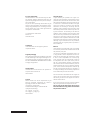
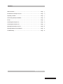
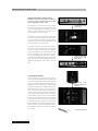
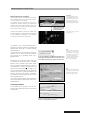
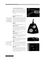
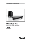
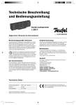
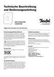
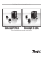
Technical specifications and operating instructions
Concept C 100
Concept C 200
Active 2.1 multimedia set with table remote control
For your information
The information in this document may be changed without advance notification and does not
represent any obligation on the part of Lautsprecher Teufel GmbH.
No part of these operating instructions may be
copied in any way, whether electronically, mechanically, using photocopies or recordings, or transferred without the prior written agreement of
Lautsprecher Teufel GmbH.
© Lautsprecher Teufel GmbH
Version 1.0
December 2008
Trademark
® All trademarks are the property of their
respective owners.
Original packaging
We recommend keeping the packaging if you want
to take advantage of the eight-week right to return goods, because we can only accept the speakers IN THEIR ORIGINAL PACKAGING. We are unable
to supply empty boxes!
Technical Data
Technical data can be found in the product description on our website at:
www.teufel.eu
Contact
Please contact our service department if you
have any questions, suggestions or if there is
anything you think we could do better.
Lautsprecher Teufel GmbH
Gewerbehof Bülowbogen · Bülowstraße 66
10783 Berlin (Germany)
Tel.: +49 (30) - 30 09 300
Fax: +49 (30) - 30 09 30 30
www.teufel.eu
2
· Concept C 100 / 200
Warranty terms
12-year warranty for speakers and 2-year warranty for power amplifiers and electronics (from
purchase date) on materials and work time, with
the exception of damage caused by incorrect use
or electrical or mechanical overload. An original
copy of our invoice is required as the warranty
document. This warranty is exclusively valid for
speakers, power amplifiers and electronics that
have been purchased from Teufel for private use
by end customers. The warranty is not valid for
speakers, power amplifiers and electronics that
the end user has purchased from a different distributor. For third-party products, the warranty
conditions of the respective manufacturers shall
apply. If the Teufel product is sold on privately, the
warranty may be transferred to the purchaser,
providing that the original proof of purchase is
also transferred.
Returns
Teufel provides an eight-week right to exchange
or return the product with reimbursement of the
full purchase price paid.
The return of individual components from a set
is only possible if these components are also offered for sale separately by Lautsprecher Teufel.
If one or more components are returned, any
price discount given by Lautsprecher Teufel on
all components in a set as part of the price for
the set is waived. When returning a component,
the customer will be reimbursed for the price difference between the set price and the purchase
price of the individual components retained by
him/her. The financial outcome for customers is
as if they had bought the remaining components
at the individual price from the outset.
You can find more information on the subject of
returns on the returns form that accompanies
the delivery or online in the support area of our
website www.teufel.eu.
If you need to return an item, do not act without
the prior agreement of Lautsprecher Teufel.
We can only process and accept returns if you
have informed us first by phone and discussed
the procedure with us!
Contents
Table of contents . . . . . . . . . . . . . . . . . . . . . . . . . . . . . . . . . . . . . . . . . . . . . . . . . . . . . . . . . . . . . Page
3
Introduction to Concept C 100 / 200 . . . . . . . . . . . . . . . . . . . . . . . . . . . . . . . . . . . . . . . . . . . . . Page
4
Unpacking · Contents . . . . . . . . . . . . . . . . . . . . . . . . . . . . . . . . . . . . . . . . . . . . . . . . . . . . . . . . . . Page
5
Accessories (optional) · Installation . . . . . . . . . . . . . . . . . . . . . . . . . . . . . . . . . . . . . . . . . . . . . Page
6
Set-up . . . . . . . . . . . . . . . . . . . . . . . . . . . . . . . . . . . . . . . . . . . . . . . . . . . . . . . . . . . . . . . . . . . . . . . Page
7
Connecting the Concept C 100 . . . . . . . . . . . . . . . . . . . . . . . . . . . . . . . . . . . . . . . . . . . . . . . . . . Page
8
Connecting the Concept C 200 . . . . . . . . . . . . . . . . . . . . . . . . . . . . . . . . . . . . . . . . . . . . . . . . . . Page
9
Operating the Concept C 100 / 200 . . . . . . . . . . . . . . . . . . . . . . . . . . . . . . . . . . . . . . . . . . . . . . Page 10
Operating elements on the subwoofer . . . . . . . . . . . . . . . . . . . . . . . . . . . . . . . . . . . . . . . . . . . Page
11
Troubleshooting . . . . . . . . . . . . . . . . . . . . . . . . . . . . . . . . . . . . . . . . . . . . . . . . . . . . . . . . . . . . . . Page 12
Manual Version 1.0
· Concept C 100 / 200
3
Introduction to Concept C 100 / 200
Dear Lautsprecher Teufel customer,
Thank you for buying a Concept C 100 / 200
system. With this Teufel product you have bought
a 2.1 multimedia speaker set that offers excellent
sound quality, despite its compact size.
This set can be operated independently, without
an additional amplifier directly through a PC or
CD player. Other stereo sources with analogue
outputs, such as MP3 players, satellite receivers,
TV sets, Xbox, PlayStation or DJ mixers, can also
be used very successfully with the Concept C
range.
The Concept C range subwoofer has three
integrated power amplifiers: one for the bass
speaker and two for the satellites. There is an
analogue stereo input at the rear for direct
connection e.g. to sound cards or MP3 players.
The USB port on the Concept C 200 is especially
useful for computers with low quality sound cards
or no sound cards at all.
Concept C 100
Please take a note of the serial number that can
be found on a sticker on the box and the invoice
number (which can be found on the invoice) here:
My invoice number is
Because the set-up has a major influence on the
sound characteristics of any speaker system,
we recommend that you take the time to
position everything correctly. These operating
instructions contain all of the information
necessary to correctly set up and operate our
Concept C multimedia sets.
Please read the instructions included carefully,
paying particular attention to the safety
information, before operating the unit and store
them in a safe place for future reference. We
recommend that you keep the packaging.
......................................................................................
My serial number is
......................................................................................
The serial number and the invoice number make
it easier for us to process your request quickly if
you require service.
If you encounter difficulties during operation or
if you think that there is something wrong with
the device, please read the “Troubleshooting”
section on page 12.
You can find answers here to the most frequently
asked questions.
Please contact our service department if you have any questions, suggestions or if
there is anything you think we could do better.
All information is provided without
Lautsprecher Teufel GmbH
Gewerbehof Bülowbogen · Bülowstraße 66
10783 Berlin · Germany
4
· Concept C 100 / 200
Tel.: +49(30) 30 09 30 0
Fax: +49(30) 30 09 30 30
www.teufel.eu
guarantee of correctness. Subject to
technical changes, typing errors and
mistakes.
Unpacking · Contents
Unpacking
Fold back the flaps on the upper side of the
box, remove the polystyrene pieces and lift
the speakers out of the box carefully.
First please check that all
system components are
included.
We recommend retaining the boxes in order to
ensure safe transport for any later servicing.
4
Subwoofer
CC 100 SW
Please note:
Please keep the boxes for the
eight-week return period at
least, as we can ONLY repay
the full purchase price if the
products are returned in the
ORIGINAL PACKAGING in which
they were supplied!
Concept C 100 contents
41 x Subwoofer CC 100 SW with integrated
2.1 amplifier
42 x Satellite speakers CE 10 FCR
42 x Cloth frames for CE 10 FCR
42 x Table bases for CE 10 FCR incl. screws
48 x Self-adhesive rubber pads for the table
bases
41 x Table remote control CC 21 RC
41 x Mains power cable
42 x U profiles for speaker stand setup
4
Satellite speakers CE 10 FCR
(incl. cloth frame
and table base)
4
4
All optional accessories can
easily be ordered as required,
e.g. from the accessories area
on our website:
www.teufel.eu
Table remote control CC 21 RC
Power supply cable
First, please check that the
system is complete!
Concept C 200 contents
4
41 x Subwoofer CC 200 SW with integrated 2.1 amplifier
42 x Satellite speakers CE 20 FCR
42 x Cloth frames for CE 20 FCR
42 x Table base for CE 20 FCR incl. screws
48 x Self-adhesive rubber pads for the table
bases
41 x Table remote control CC 21 RC
41 x Mains power cable
42 x U profiles for speaker stand setup
Subwoofer
CC 200 SW
Satellite speakers
CE 20 FCR
(incl. cloth frame and table base)
4
4
Table remote control
CC 21 RC
4
Mains power cable
· Concept C 100 / 200
5
Accessories (optional) · Installation
Assembling the table bases
If required, use the screws supplied to attach the satellite speakers CE 10 FCR or CE 20 FCR to the table
bases provided, as shown in the diagram. For acoustic reasons we don’t recommend placing the satellites straight onto the table. We also recommend that you stick the rubber pads supplied to the points
on the table bases provided for this purpose, to ensure a safe and secure position and to protect the
top of the table as well as possible.
The M 50 P base or the Shortlock wall bracket, for example, are also available in our webshop. They provide a secure yet flexible way of displaying your satellites, as an alternative to the table bases supplied.
For fixing the satellites to the optional speaker stand M 50 P you will need to use the included U profiles.
Accessories
The Concept C range is supplied without connecting cables, because customers have different requirements. You can find the cable you need in our online shop (www.teufel.de), for example, in the “accessories” section. More optional accessories for the system are shown here:
You can order the accessories shown here from Teufel
online at:
www.teufel.eu
Speaker stand M 50 P
Bases developed especially for Teufel
satellite speakers. The speaker cable is
hidden inside the base.
Height:
Adjustable between 80 and 120cm.
Design:
Metal, black. They are supplied as a
pair.
6
· Concept C 100 / 200
Shortlock wall bracket
The ideal wall mounting for
satellites from Teufel Concept 100 / 200 systems because the required screw
threads are already on the
back. Allows unobtrusive
and secure mounting on ceilings, sloping ceilings or walls. The wall brackets
are available in black or silver, but only come in
pairs.
Set-up
Set-up as a PC system
When using the Concept C 100 / 200 as a PC speaker sound system, it is advisable to focus on the
sound requirements of the PC workplace, i.e. the
area where the screen and the listener are located.
The satellite speakers are placed (using the table
bases included) next to the computer monitor at
the same distance from it left and right or attached to the wall.
Attachment at ear height is optimal, but anything
in the range between 0.80 and 1.60 metres is
completely acceptable. If the values are outside
the recommended range, you can slightly tilt the
front speaker. We recommend using our “Shortlock” wall brackets (see page 6) for wall mounting.
These wall brackets allow for horizontal and vertical mounting.
Satellite
left
Subwoofer
Satellite
right
Note
The nearer you position the
satellites to the listening
position, the greater the
subjective impression of sound
and the maximum undistorted
reproduction level.
You can put the subwoofer anywhere you wish; it
does not affect the other speakers. Placement
within a straight line between the two front satellites, e.g. under the desk, is ideal.
Set-up as a stereo system
The Concept C 100 can also be used in smaller
rooms up to 15m2 as a complete stereo system
for listening to music and the Concept C 200 can
even be used in rooms up to 20m2.
Tip
The closer you place the subwoofer to a wall or corner, the louder
you can hear the bass playback.
Subwoofer
Satellite
left
Satellite
right
If possible, the satellite speakers should be set up
at the same distance from the listener left and
right or attached to the wall. The “M 50 P” heightadjustable base also offers an alternative to the
“Shortlock” wall brackets described above, alongside the table bases supplied. Using the bases automatically guarantees optimum playback height
for satellite speakers. Select a position height of
between 40cm and 1.60m.
If you are unable to observe these distances, you
can slightly tilt the front speaker towards the
listening area. The Shortlock wall bracket allows
horizontal and vertical alignment to the listener.
You can put the subwoofer anywhere you wish; it
does not affect the other speakers.
· Concept C 100 / 200
7
Connecting the Concept C 100
Analogue connection to a stereo source
Computer sound card, MP3 player, satellite receiver, TV set, games console, CD player, DJ mixer,
Discman, Walkman and much more.
The Concept C 100 is perfect for direct connection to any common music playback device that
has one or two analogue audio outputs. These are
usually a 3.5mm stereo mini-jack socket or two
cinch sockets (“line out left/right”).
Example image of a sound card
connector panel
Analogue connection
from PC (line out) to subwoofer (aux in)
The outputs are directly connected to the stereo
line in left/right on the subwoofer using the stereo cinch cable. The Y-adapter cable (mini-jack on
stereo cinch) can also be used for appliances with
mini-jack outputs (e.g. sound cards).
To guarantee that all of the functions of the table remote control supplied work correctly, the
“Mic Out” output on the back of the subwoofer
must be connected to the microphone input on
the PC. A standard 3,5 mm jack cable is used for
this purpose. Without this connection, nearly all
of the functions of the table remote control (see
page 10) can still be used independently. Only the
integrated Microphone input (“MIC”) will not
work.
Connection from subwoofer (mic out) to PC
(line in / mic in)
Example image of a sound card connector panel
Connecting the satellites
The two satellites are connected directly to the
screw grips on the subwoofer with the cable clips
provided, using a speaker cable. Strip and split the
ends of the speaker cable as shown. Speakers and
amplifiers have corresponding [+] and [–] clamps.
The individual strands of a speaker cable are normally clearly colour coded. It is important to observe the correct polarity when connecting the
speakers: the plus pole of the speaker connects to
the plus pole of the amplifier and the minus pole
of the speaker to the minus pole of the amplifier.
Connecting the cables with the incorrect phases
can result in thin sound, weak bass and reduced
stereo characteristics. Therefore it is important
that all speakers are connected with the correct
polarity in order to ensure an appropriate threedimensional atmosphere and correct alignment
of the sound.
Connection from
satellite speakers to
subwoofer
Two core speaker cable
8
· Concept C 100 / 200
Connecting the Concept
Anschluss
C 200
Digital connection to a computer
The Concept C 200 has a USB interface, in addition to analogue stereo cinch inputs (for connection, see Concept C 100, page 8).
The speaker set can be connected directly to a
notebook or desktop computer. PC owners with
onboard sound cards with moderate sound quality find it easy to improve the sound quality of
their computer at the source.
Important
Please appreciably reduce the
volume BEFORE using the USB
port of the Concept C 200. The
USB connection may create
distinctly higher output volumes
than the analogue connection!
Example image of a USB port on
a laptop
Digital connection from
PC (USB, type A) to subwoofer (USB, type B)
Connect a free USB port* on your PC or Mac using
a USB cable (type A to type B) with the “USB” input
on the subwoofer. The Concept C 200 amplifier
now works like an external sound card.
The Concept C 200 is usually automatically recognised by operating systems like Windows XP,
Windows Vista or Mac OS X – without installing
additional drivers.
In some cases it may be necessary to switch the
Concept C 200 to "active" in the audio menu of
your computer or to specifically select it as a
playback device.
Alternatively you can use the stereo cinch input
as described on the previous page or connect
another source appliance there. Both signals
will be reproduced simultaneously, as soon as a
USB connection is active at the same time. The
volumes of the cinch input (Q on page 11) can
then be controlled separately in your operating
system’s audio mixer to avoid interference, for
example, and can also be “muted” if necessary.
The volumes of the USB signal can also be controlled separately there.
The microphone input (“MIC”) on the front of the
table remote control supplied only works with a
USB connection.
* You can use USB 1.0/1.1 as well
as USB 2.0 ports.
If this speech bubble (or its equivalent, depending on the
operating system) is displayed, the Concept C 200 has been
successfully recognised by your computer and can be used.
Note
Please note that when using the
USB and the stereo cinch input
at the same time, separate volume control is also possible using
the internal control on your
computer. You should also mute
one of the connection types
there to avoid interference.
Note
Please note that the microphone
input (“MIC”) on the front of the
table remote only works when
the USB connection is used.
Connecting the satellites
The satellites for the Concept C 200 are connected as described for the Concept C 100 on the
previous page.
You might have to select the Concept C 200 as a playback
device in the audio menu of your operating system. It is
shown as a "USB Multimedia Audio Device".
· Concept C 100 / 200
9
Operating the Concept C 100 / 200
Connecting the table remote control
Connect the cable for the table remote control
supplied to the back of the subwoofer using the
connection provided (“Remote Control”, page 11,
W). Please note that this cable can only be connected one way round (with the arrow pointing to
the right). Connect the cable carefully to avoid
damaging it.
Note
The Concept C 100 / 200 can
be fully controlled using the
table remote control if it is
connected to the subwoofer as
shown in diagram 1.
Alternatively you can switch
between operation and standby
using the "standby" button on
the front of the subwoofer (see
diagram 4).
Note
The microphone connection
only works when the “Mic Out”
output (Concept C 100) or the
USB connection (Concept C 200)
are used as described on pages 8
and 9. Otherwise this connection
will not work.
10
· Concept C 100 / 200
Operating the Concept C 100 / 200
Q Power
You can switch the Concept C 100 / 200 to standby
mode and switch it back on again using this button.
In standby mode the “Power” lettering will light up
red. When switched on the button will light up blue.
If neither the button nor the lettering are lit up,
then the power supply to the subwoofer is being
interrupted or the table remote control is not
connected.
W Volume
You can control the volume of the Concept C 100 /
200 using the infinite control dial.
E Volume (display)
The blue LED indicates the current volumes of
the Concept C 100 / 200. The display only refers to
the relative volumes of the Concept C 100 / 200.
Separate volume settings that may be available
on the source appliance itself (PC, Mac, CD player,
etc.) are not shown here.
R Bass
You can control the bass of the Concept C 100 /
200 using the infinite control dial.
T Bass (Display)
Both blue LEDs display the current basses of the
Concept C 100 / 200. The bottom left LED indicates
a high bass proportion and the top right LED
shows that the bass proportion is lower.
Y Phones
You can connect headphones here using a 3.5mm
jack cable. As soon as a jack cable is connected, the
Concept C 100/200 will automatically mute the satellites and the subwoofer.
U Mic
You can connect a microphone here using a 3.5mm
jack cable. The microphone will automatically be
recognised by the computer. Depending on your
operating system, you might receive notification
that a recording device has been connected or
you may have to confirm it.
I Standby
You can use this button to switch the Concept C
100/200 to standby mode or to switch it on again.
In standby mode the ring around the button will
light up red and in operation it will be blue. If the
ring does not light up the power supply to the
subwoofer has been interrupted.
Ĕ Arrow!
Fig. 1: Connecting the table remote control
T
R
T
W
Q
E
Fig. 2: Table remote control (top)
Y
Fig. 3: Table remote control (front)
I
Fig. 4: Subwoofer (front)
U
Operating elements on the subwoofer
Explanation of symbols
Aux In
R
Aux In
Q
Q
L
R
L
Remote Control
Remote Control
W
W
Mic Out
E
USB
R
The arrow-headed lightning
symbol in an equilateral triangle
indicates the presence of a
dangerous non-insulated electrical voltage within the system
housing and therefore a risk of
electrical shock..
Model CC 200 SW
Model CC 100 SW
+
+
–
Right
T
–
Right
T
Left
Left
Speaker Out
Speaker Out
U
I
Power
AC 220-240 V~50/60 Hz
150 Watts
Fuse T 2 AL/250 V
Y
On
Off
Serial No.
Serial No.
Warning: To reduce the risk of fire or electrical shock
do not expose this appliance to rain or moisture.
Caution
Risk of electric shock!
Do not open!
Attention
Risque de choc electric! Ne pas ouvrir!
Subwoofer power amplifier Concept C 100
Q Aux In (R / L)
You can connect an audio source appliance (PC, Mac,
CD player, etc) to the Concept C 100 / 200 here. You will
also need a stereo cinch cable (possibly with adapter).
W Remote Control
Connect the cable provided for the table remote control here. Please note that this cable can
only be connected one way round (with the arrow
pointing to the right). Connect the cable carefully
to avoid damaging it.
E Mic Out (Concept C 100 only)
Using a 3.5mm jack cable, connect the Concept C
100 Subwoofer to the “Line In” or “Mic In” input
of your PC or Mac so that you can use the microphone input (“MIC”) on the table remote control
(see page 11, U).
R USB (Concept C 200 only)
Connect the Concept C 200 to your PC or Mac
here using the USB cable (connector type “B” to
“A”). We recommend this type of connection for
the Concept C 200 because the microphone input
(“MIC”) at the table remote control can only be
used if the Concept C 200 is connected to the PC
via USB.
U
I
Power
AC 220-240 V~50/60 Hz
300 Watts
Fuse T 3.15 AL/250 V
Y
On
Off
Warning: To reduce the risk of fire or electrical shock
do not expose this appliance to rain or moisture.
Caution
Risk of electric shock!
Do not open!
The exclamation mark in an
equilateral triangle, as affixed
to the appliance, is to make
the user aware of important
operating and maintenance
instructions.
Attention
Risque de choc electric! Ne pas ouvrir!
Subwoofer power amplifier Concept C 200
T Speaker Output (Right / Left)
Connect the speaker cable from the two satellites
here. Please observe the plus and minus polarity
and the set-up of the satellite speakers (right =
right satellite, left = left satellite).
Y Power (On / Off)
When set to “Off ”, the subwoofer is switched off,
and when set to “On” it is switched on.
U Mains cable
Connect the mains power cable supplied here, in
order to connect the Concept C 100 / 200 to the
power supply.
This product complies with
European Community guidelines
89/336 EEC and 72/23 EEC
The dustbin symbol printed
on our products’ type plates
and amplifiers states that
Lautsprecher Teufel guarantees
proper disposal of these speakers
and subwoofers in line with the
Electrical and Electronic Appliance Act.
I Fuse
You can change the
mains fuse here if required – it should only
be replaced with one
of the same type and
amperage. Please use
a suitable screwdriver
for changing the fuse,
as shown in the dia-
This product corresponds to
standards DIN EN 61140 (VDE
0140-1) and IEC 60417 of safety
class II and does not require
a safety plug, just the plug
included (2-pole). The casing has
reinforced or double insulation
against electric shock.
gram opposite.
Only change the fuse if the subwoofer is completely disconnected from the mains power
supply, otherwise fatal injury could result!
· Concept C 100 / 200
11
Troubleshooting
“The subwoofer is buzzing”
The Concept C 100 / 200 has a powerful transformer and a generously proportioned power pack
that make its high output performance possible.
These components can create a very quiet, unobtrusive buzzing sound that can be heard at a
short distance from the back of the subwoofer in
quiet rooms if there is no signal present. It cannot be avoided in this price category. During operation this light buzzing will disappear because it
is masked by the sound output.
On the other hand, if the buzzing can clearly be
heard from a distance of more than a metre and/
or can also be heard from the satellites, there
is possibly a defect – assuming the subwoofer is
not touching other appliances. In some cases, it
could come from connection to other appliances,
through equalising currents that are caused by
different casing potentials or similar.
Please read the following instructions for a solution to the case above:
1. The subwoofer is connected to a different power circuit from the rest of the equipment. Ensure that all linked appliances (including the PC
if connected) are connected to a single power
circuit or plug.
2.The aerial connected to the equipment or TV
has a different ground potential than the socket. To test this, simply remove all aerial cables from the wall socket. If the buzzing stops,
you need a sheath current filter available from
electronics retailers, often in the car stereo
department.
3.A mains filter that can be bought separately, to
which all appliances must be connected, may be
useful in eliminating the buzzing.
4.A multiple socket strip can sometimes prove
to be responsible for creating buzzing noises.
To test this, disconnect the plug strip and plug
the subwoofer’s mains plug directly into a wall
socket.
5. You can also try turning the mains plug around
and inserting it into the socket the other way
up, inasmuch as your mains plug/socket allows
this.
6.It can be useful to create an additional earth by
fixing a cable (e.g. speaker cable) to the metal
screw of the power amplifier and fixing the other
cable end e.g. to the heating pipe or PC casing.
12
· Concept C 100 / 200
“There is no sound – neither from the satellites nor from the subwoofer”
Please check whether the “Standby” operating
light on the front of the subwoofer lights up RED
or BLUE. If not, please change the fuse for one of
the same type. The mains fuse on the subwoofer
may have blown, possibly as the result of a power
surge. The fuse is located at the mains power cable output on the back of the subwoofer (see diagram on page 11, point 8). The subwoofer should
now be ready for use again. Only change the fuse
if the subwoofer has been completely isolated
from the mains power supply!
“There is no sound or distorted sound from
one of the satellites – the other satellite is
working”.
In order to pinpoint the defect more specifically,
please briefly swap the non-functioning satellite
for the functioning satellite in order to determine whether the defect is in the satellite or the
subwoofer electronics. If the previously non-functioning satellite plays on the other channel of the
subwoofer, the defect is probably in the subwoofer electronics. If the satellite does not play on
the other channel, the satellite is defective.
“There is no sound from the subwoofer – both
satellites are working”
You can check the function of the subwoofer by
only connecting the signal of a “secure” source,
e.g. a portable CD player, to the line in left/right
cinch input on the subwoofer. If the subwoofer
now plays, it could not have been getting the correct signal before. Either the cinch cable is defective or the output of your source appliance is not
generating a signal.
Alternatively, you can reduce the volume level of
the subwoofer, remove the subwoofer cinch cable
from the PC/CD player, steadily and carefully raise
the level and touch the inner cinch thermistor
with your finger. If you can now hear buzzing or
crackling, there is an error in the PC/CD player
or its settings. If the subwoofer remains silent,
please contact our service department.