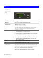
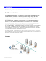
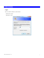
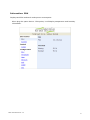
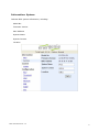
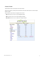
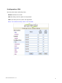
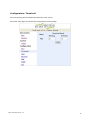
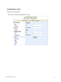
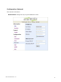
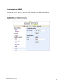
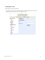
1
PDU
User Manual
Table of Contents
1. Introduction ............................................................................................................ 1
2. PDU Package ........................................................................................................... 2
3. Function.................................................................................................................. 3
4. Installation .............................................................................................................. 5
5. Web Interface .......................................................................................................... 7
1. Introduction
The PDU is an Internet ready device designed and is equipped with an intelligent currentmeter (True RMS) that will indicate the total power consumption of a power strip.
The PDU offers an easy set up and user-friendly communication software. This software
provides the function that assistant manager to remotely monitor the multiple PDU power
consumption to realize the total current power consumption and utilization for the
enterprises.
Features:
z Built-in web server, manager can real time to monitoring the current consumption of
the power strip.
z Build-in true RMS current meter.
z Setup easily, meter can read the IP address directly.
z Homepage support SSL.
z Provide audible alarm when the power consumption over the threshold of warning and
overload.
z Send the email and traps when the power consumption exceed the trigger value of
warning or overload to the PDU.
z Provide utility, it can monitor a large mount of PDU at the same time.
z Support the SNMP and provide MIB for the PDU to be monitored by NMS.
z Provide per outlet power protection by the circuit breaker.
z Real time to control outlets of PDU.
z Indicate outlets status with LED.
z Support power on sequence.
z Option accessory can support temperature and humidity detection.
PDU User Manual Ver. 1.0
1
2. PDU Package
The standard PDU package contains a Power Distribution Unit with supporting hardware
and software. The components of the package are:
z Power Distribution Unit.
z Rack mount Brackets.
z CD-ROM, it contains:
z User Manual.
z PDU Software.
z MIB: Management Information Base for Network. (PDUMIB.mib)
z Adobe Acrobat Reader.
PDU User Manual Ver. 1.0
2
3. Function
Interface
Single current
bank
Functions
Description
Ethernet
RJ45 port for network communication port.
Audible Alarm
Warning- 1 beep in 1 second.
Overload- 3 beeps in 1 second.
Note: The audible alarm will keep beeping until the current
gets back to normal and the current is lower than the
threshold to 0.5 amps.
Function Button
z Press and release to turn off the warning beeping. The
overload beeping can not be cancelled.
z Press and hold the key after 2 beeping; it can let the meter
to show up the IP address
z Press and hold the key after 4 beeping; it can change the
way to get IP by DHCP or fixed IP.
z Press and hold the key after 6 beeping; it can reset PDU
back to default setting.
Meter
3 digits to display current and IP Address.
ID
The identification of power bank or PDU.
LED Indicator
SSL (yellow): Light on means web access is protected by SSL.
DHCP (Green): Light on means PDU gets IP address by DHCP.
PDU (Green): Indicate each output power status.
Status (Red): Indicate each circuit status. (by model)
PDU User Manual Ver. 1.0
3
ENV
RJ11 for ENV probe attached.
Circuit Breaker
Overload power protection.
PDU User Manual Ver. 1.0
4
4. Installation
This section will provide a quick instruction to install the PDU.
Rack Mount Instructions
A) Elevated Operating Ambient - If installed in a closed or multi-unit rack assembly, the
operating ambient temperature of the rack environment may be greater than room
ambient. Therefore, consideration should be given to installing the equipment in an
environment compatible with the maximum ambient temperature specified by the
manufacturer.
B) Reduced Air Flow - Installation of the equipment in a rack should be such that the
amount of air flow required for safe operation of the equipment is not compromised.
C) Mechanical Loading - Mounting of the equipment in the rack should be such that a
hazardous condition is not achieved due to uneven mechanical loading.
D) Circuit Overloading - Consideration should be given to the connection of the equipment
to the supply circuit and the effect that overloading of the circuits might have on over
current protection and supply wiring. Appropriate consideration of equipment nameplate
ratings should be used when addressing this concern.
E) Reliable Earthing - Reliable earthing of rack-mounted equipment should be maintained.
Particular attention should be given to supply connections other than direct connections to
the branch circuit (e.g. use of power strips)."
Diagram
PDU User Manual Ver. 1.0
5
Hardware
1.
Install mounting brackets.
2.
The PDU comes with brackets for mounting in a rack. To mount the PDU into a rack
performs the following procedure:
3.
Attach the mounting brackets to the unit, using the four retaining screws provided for
each of the brackets.
4.
Choose a location for the brackets.
5.
Align the mounting holes of brackets with the notched hole on the vertical rail and
attach with the retaining screws.
6.
Connect input and output power.
7.
Connect Ethernet cable to the PDU.
8.
Switch on the PDU.
Note 1:
The default setting for the way to get IP address is DHCP. If PDU can not get the IP from
DHCP server, the IP address will stay at 192.168.0.216
Note 2:
TO SETUP THE NETWORK SYSTEM FOR PDU, STRONGLY RECOMMAND TO BUILD UP THE
POWER MONITORING NETWORK SYSTEM ISOLATED WITH THE OTHERS, IN ORDER TO
KEEP THE STABILITY OF GETTING POWER INFORMATION AND SYSTEM OPERATION.
PDU User Manual Ver. 1.0
6
5. Web Interface
Login:
Input the PDU IP address in web browser.
Default ID is snmp.
Password is 1234.
PDU User Manual Ver. 1.0
7
Information: PDU
Display total PDU and each outlet power consumption.
When plug the option device - ENV probe, it will display temperature and humidity
information.
PDU User Manual Ver. 1.0
8
Information: System
Indicate PDU system information, including:
Model No.
Firmware Version
MAC Address
System Name
System Contact
Location
PDU User Manual Ver. 1.0
9
Control: Outlet
Indicate PDU outlet on/off status and control outlet.
Select the outlet by checking the box and then click ON or OFF button to control output
power for PDU
Monitored PDU series does not support this function.
ON: Press the icon to turn on the assigned outlets.
OFF: Press the icon to turn off the assigned outlets.
OFF/ON: Press the icon to reboot the assigned outlets.
PDU User Manual Ver. 1.0
10
Configuration: PDU
Set the outlet name and delay time.
Name: Rename the outlet.
ON: Set delay time for power on sequential.
OFF: Set delay time for power off sequential.
Note: The maximum delay time is 255 seconds.
PDU User Manual Ver. 1.0
11
Configuration: Threshold
Set the warning and overload threshold for each circuit.
Set lower and upper threshold for temperature and humidity.
PDU User Manual Ver. 1.0
12
Configuration: User
Change ID and password.
Default ID is snmp and password is 1234.
PDU User Manual Ver. 1.0
13
Configuration: Network
PDU network information
Enable DHCP: Change the way to get IP address for PDU.
PDU User Manual Ver. 1.0
14
Configuration: Mail
When event occurs, PDU can send out email message to pre-defined account.
Email Server: The Email Server only support to be input domain name, not IP address.
Sender’s Email: Input the sender email address.
Email Address: Input the recipient email address.
The message in the email:
Indicate OutletA~H-XXXXXXXX status in order
X=0 : means the power off.
X=1 : means the power on.
Note: Make sure DNS server can resolve the Email Server’s domain name.
PDU User Manual Ver. 1.0
15
Configuration: SNMP
When event occurs, PDU can send out trap message to pre-defined IP address.
Trap Notification: Set receiver IP for trap.
Community: Set SNMP community.
Read Community is public and fixed.
Default Write Community is “public” and can be modified by user.
PDU User Manual Ver. 1.0
16
Configuration: SSL
Enable SSL for web communication.
User must input the correct ID and password to enable SSL function. The ID and
password must be the same with the setting in “User”.
PDU User Manual Ver. 1.0
17