1
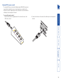
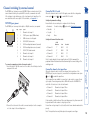
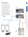
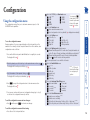
AV4PRO-DP User Guide COMPUTER KVM SPK USB1 USB2 MODE www.adder.com Configuration Using the configuration menu..................................................12 General configuration................................................................13 Changing hotkeys..................................................................13 Mouse switching....................................................................13 OPTIONS port speed..............................................................13 OPTIONS port channel control behaviour............................13 Switching mode.....................................................................14 Miscellaneous functions........................................................14 Performing upgrades.................................................................15 Further information Getting assistance.......................................................................22 Appendix 1 – Cable pin-outs......................................................23 Warranty.....................................................................................24 Safety information.....................................................................24 Radio Frequency Energy............................................................25 Index Mounting......................................................................................6 Connections..................................................................................7 User console.............................................................................7 Computer systems....................................................................8 Power in connection................................................................8 Optional RC4 remote control..................................................9 Channel switching by external control.....................................10 Synchronising multiple units......................................................11 Installation Selecting a computer.................................................................17 To select a computer using the front panel.........................17 To select a computer using hotkeys.....................................18 To select a computer using the mouse buttons...................19 To lock access to the computers...........................................20 Autoscanning..............................................................................21 What is True Emulation?..............................................................3 AV4PRO-DP features - front and rear.........................................4 What’s in the box.........................................................................5 What you may additionally need................................................5 Operation Introduction Contents 1 2 DisplayPort video Full support is provided for DisplayPort video connections up to 2560 x 1600 at 60Hz, 30bpp, 4 lanes @ 2.7GBits/s, 10.8GBits/s. Multiple switching The attached peripheral devices can be switched collectively to any computer system, or can be linked to separate systems to achieve multiple tasks in parallel. Multiple switching can be controlled from the front panel buttons, hot keys or mouse buttons. USB keyboard and mouse Dedicated keyboard and mouse ports with support for full speed USB emulation. True Emulation Earlier USB KVM switches relied upon standard keyboard and mouse templates to inform each computer system how to deal with the connected peripherals. The AV4PRO-DP succeeds in harvesting the true identities of the connected keyboard and mouse and presents those ‘real’ profiles concurrently to every system. Thus, specialist keyboards and mice can be fully supported. COMPUTER KVM SPK USB1 USB2 1 SPK KVM USB peripheral. The AV4PRO-DP front panels make it straightforward to control which peripherals should connect to each system. The AV4PRO-DP units feature True Emulation which ensures that the full characteristics of the connected keyboard and mouse are passed to every system. The KVM, speakers and two separate USB devices attached to the AV4PRO-DP units can either be switched in unison, as normal, or you can mix your peripherals between any of the systems to suit your current tasks. For instance, you could be creating emails on one system, listening to a soundtrack from another while a third is sending documents to your printer and a fourth is performing another task with a different MODE www.adder.com USB Remote wakeup The USB Remote Wakeup feature is fully supported. Any connected computer can go into sleep mode and be awakened (when its channel is selected) as soon as you press a key or move the mouse. The computer and peripherals must support the USB Remote Wakeup feature. Thank you for choosing the AV4PRO-DP professional video and peripheral switch from Adder Technology. In common with all members of the AdderView Pro range, the AV4PRO-DP unit offers high quality video switching (DisplayPort 1.1 compliant) together with individual sharing of peripherals between up to four computers. Introduction 2 Emulated USB switching The issues with interpreting the complex USB data streams and recreating (or Emulating) the identity of attached USB devices were eventually solved, leading to the creation of the Emulated USB switch. A neat side effect of the technique used is that each computer can be fooled into thinking that the USB device is permanently connected to it, even when the device is switched to another computer. This means that the enumeration process for the USB device takes place only once, during the first power on. After that, a computer merely sees a dormant version of the USB device whenever the device is actually connected to a different computer. However, it remains a complex task to dynamically assume the identity of a USB device, distribute it among the connected computers and maintain all of the necessary signals, states and processes. Therefore, manufacturers have previously relied upon a fixed keyboard and mouse profile that is declared to each computer, regardless of the actual connected devices. This precluded the use of any special keyboard or mouse features over and above the standard layouts. multiple functions to the computer may not be supported. Enumerated USB switching The earliest attempts to switch USB devices applied a relatively ‘hands off’ approach. Enumerated USB switches are the electronic equivalent of those old mechanical KVM switches with a large knob on the front. Enumerated switches are so called because a connected USB device will be required to perform a full initiation (a process called Enumeration) every time it is switched; just as if you had pulled out the plug and then reconnected it. Enumerated switches simply pass all signals straight through between the USB device and the computer, they do not attempt to interpret any data. For most devices, this offers an advantage because the switch just leaves them to get on with their jobs without any interference or any hit on performance. However, it means that a USB keyboard or mouse cannot be used to control the switching process - a quick and simple control method expected by most users. Reliability of switching is also an issue that has plagued enumerated switches, especially when used with certain USB devices and particular operating systems. True Emulation Mindful of the limitations associated with the USB USB OTHER USB DEVICE previous USB switching techniques, we set about KEYBOARD MOUSE creating a more effective and elegant solution. After a great deal of research and development, HOST True Emulation is the result. CONTROLLER True Emulation allows the complete identity of the keyboard and mouse to be copied and then presented to all of the connected computers. EMULATION ENGINE This means that a keyboard* offering specialist function keys or a mouse with extra features can be fully supported at each computer. As with the previous emulation method, the unselected computers will continue to see the identities USB USB USB USB HUB HUB HUB HUB of the keyboard and mouse, which means that no enumeration is necessary when their link becomes active once again. This not only helps PC PC PC PC to speed up the rate of reconnection, but also 1 2 3 4 raises the reliability of switching because USB links are at their most vulnerable during the The emulated section of enumeration process. the switch is shown in True Emulation relies upon a high speed circuit, blue and handles only the called an Emulation Engine, to fully emulate the USB device identities and also interpret keyboard keyboard and mouse. The and mouse data streams. The result is full support green enumerated section of the switch handles other for KVM switching control via hotkey presses or the third button/scroll wheel of a mouse. USB devices and also uses the USB hubs to link with True Emulation is not necessarily required by other USB devices, which is why you will also the computers. find two enumerated circuits included (shown in green within the block diagram) alongside the True Emulation feature (shown in blue). This allows those other USB devices to operate at their highest speeds, without any intervention. The enumerated circuits benefit greatly from the USB Hubs that are jointly used with the True Emulation system. Because they interface directly and permanently with each computer, they help to stabilise the dormant links, making errors during enumeration much less likely. The dual switching arrangement provides further flexibility because the True Emulation and enumerated sections can be switched in unison or independently of each other, as required. Thus, your various peripherals can operate with different computers at the same time. * HID and CCID specification USB keyboards are supported. Keyboards that present True Emulation represents a significant breakthrough in sharing USB devices between two or more computer systems. Until this point, the problem has been how to create a USB switch that provides all of the following: • Quick, transparent and reliable switching, • Accurate representation of the connected USB keyboard and mouse, • Switching control via the connected USB keyboard and/or mouse. The difficulty in achieving all of the above requirements has been due to the complexity of the USB standard. This has led to various problems that have spawned a number of possible solutions. What is True Emulation? 3 AV4PRO-DP features - front and rear KVM SPK USB1 USB2 MODE www.adder.com COMPUTER button Press to change to the next computer channel. MODE button Press to determine which peripherals should be switched to another computer channel (will occur when the COMPUTER button is pressed. Indicators The four indicators (KVM, SPK, USB1, USB2) show which peripherals are switched to the current computer channel OR (as you begin pressing the MODE button) the peripherals that will be switched during the next press(es) of the COMPUTER button. 3 2 1 USB 1 5V USB 2 2A USB2.0 SWITCHED OPTIONS Power input The power supply connects here. User console Connect the DisplayPort video display, USB keyboard and mouse plus optional speakers to these connectors. Computer channels Each computer connects to one of these four channels via a DisplayPort video connector, a USB B-type connector and an audio 3.5mm jack input. User console Connect up to two USB devices to these connectors. These ports are switched in an enumerated manner (see What is True Emulation?) Options port This 10p10c port can separately support the following functions: 4 USER CONSOLE INDOOR USE ONLY The seven segment numeric display indicates the computer channel that is currently active. COMPUTER The AV4PRO-DP unit is housed within durable, metallic enclosure with all connectors situated at the rear panel. The smart front face features the control buttons and the operation indicators. • Remote control - allows a standard Adder RC4 four button remote control unit to be used to switch channels (see Optional RC4 remote control for details). • Upgrades - used to update the internal firmware when necessary by connecting to a computer. •Allows synchronisation between units for dual head operation. 4 What’s in the box Power adapter (12.5W) and country-specific power lead AV4PRO-DP unit CD-ROM CO MPU TER KV M SPK USB1 USB2 MO DE Four self-adhesive rubber feet er.c om What you may additionally need One set required per connected computer AD DE R 4 3 Audio cable 2m (3.5mm stereo jacks) Part number: VSC22 Due to the very high speed signals used by DisplayPort connections, the use of high quality cable is vital in order to ensure a reliable video connection through the switch. Low-cost non-compliant cables may lead to intermittent or distorted video. Adder recommends certified 2 metre (6 feet), high bit-rate cables, such as our VSCD10 part. For details about third-party cable solutions, please see the Products section of the VESA DisplayPort website: www.displayport.org USB cable 2m (type A to type B) Part number: VSC24 1 om der.c w.ad ww DisplayPort to DisplayPort video link cable Part number: VSCD10 2 RC4 remote control plus standard 3m patch lead Part number: RC4-8P8C ww w.a dd Synchronisation cable Part number: VSC41 Upgrade cable Part number: VSC40 Two 19” rackmount brackets and four screws Part number: RMK3 5 There are two main mounting methods: • The supplied four self-adhesive rubber feet • Optional rack brackets Rack brackets Connections The optional brackets (plus four screws), allow the unit to be secured within a standard rack slot. INDOOR USE ONLY Note: Both the AV4PRO-DP unit and its power supply generate heat when in operation and will become warm to the touch. Do not enclose them or place them in locations where air cannot circulate to cool the equipment. Do not operate the equipment in ambient temperatures exceeding 40 degrees Centigrade. Do not place the products in contact with equipment whose surface temperature exceeds 40 degrees Centigrade. Mounting Installation 5V 2.5 A UUS E CCOSERR ONNS SOOL LEE 1 4 OP TIO NS U SSWUSSBB2.0 WITITC 2.0 CHHE EDD UUS SBB2 2 UUS SBB1 1 6 Connections Connections do not need to be carried out in the order given within this guide, however, where possible connect the power in as a final step. User console 5V 2.5 A UUS E CCOSERR ONNS SOOL LEE INDOOR USE ONLY OP TIO 5V NS 2.5 A UUS E CCOSERR ONNS SOOL LEE From video monitor OP TIO From USB keyboard and mouse 5 Audio: Where required, connect the lead from your speakers to the audio socket. NS INDOOR USE ONLY 5V 2.5 3 USB devices: Where required, attach the leads from your USB peripherals to the USB sockets labelled USB1 and USB2. Note: These sockets provide enumerated (transparent) switching. A UUS E CCOSERR ONNS SOOL LEE 1 OP TIO NS UUS SBB1 1 U SSWUSSBB2.0 WITITC 2.0 CHHE EDD Note: The unit’s True Emulation feature will read the full characteristics of the keyboard and mouse and will present those to each connected computer concurrently. This ensures that specialist keyboards and mice are fully supported. 4 Video monitor: Attach the DisplayPort lead from the video monitor to the connector within the user console area. INDOOR USE ONLY To connect peripherals to the user console 1 Position your peripheral devices in the vicinity of the unit such that their cables will easily reach. 2 Keyboard and mouse: Attach the leads from your USB keyboard and mouse to the USB sockets specifically labelled with keyboard and mouse symbols. The keyboard and mouse will operate in any of the USB sockets, however, True Emulation is not available on the sockets labelled USB1 or USB2. The ports that make up the user console are where you attach the peripherals that will be shared between the computer systems. Ensure that power is disconnected from the unit. UUS SBB2 2 From speakers From USB peripherals 7 Computer systems Power in connection A UUS E CCOSERR ONNS SOOL LEE UUS SBB1 1 U SSWUSSBB2.0 WITITC 2.0 CHHE EDD From the USB port on the computer From the speaker port on the computer 4 Use a DisplayPort link cable (part number: VSCD10) to connect the video output of the computer’s graphic port to the video port of the required channel on the rear of the unit. 4 OP TIO NS UUS SBB2 2 Note: Both the unit and its power supply generate heat when in operation and will become warm to the touch. Do not enclose them or place them in locations where air cannot circulate to cool the equipment. Do not operate the equipment in ambient temperatures exceeding 40 degrees Centigrade. Do not place the products in contact with equipment whose surface temperature exceeds 40 degrees Centigrade. 2 2 Connect the IEC connector of the supplied country-specific power lead to the socket of the power adapter. 1 UUS SBB1 1 U SSWUSSBB2.0 WITITC 2.0 CHHE EDD UUS SBB2 2 Due to the very high speed signals used by DisplayPort connections, the use of high quality cable is vital in order to ensure a reliable video connection through the switch. Low-cost non-compliant cables may lead to intermittent or distorted video. Adder recommends certified 2 metre (6 feet), high bit-rate cables, such as our VSCD10 part. For details about third-party cable solutions, please see the Products section of the VESA DisplayPort website: www.displayport.org From the video port on the computer 5V 2.5 To connect the power supply 1 Attach the output lead from the power adapter to the 5V socket on the rear panel of the unit. To connect a computer system 1 Ensure that power is disconnected from the AV4PRO-DP unit and the system to be connected. 2 Use a USB cable (type-A to type-B) to link a USB port on the computer system to the USB port of the required channel on the rear of 2 the unit. 3 If required, use a stereo audio link cable 1 (3.5mm jacks at either end) to link the speaker port on the computer system to the audio port of the required channel on the rear of the unit. The AV4PRO-DP unit is supplied with a 12.5W power adapter. There is no on/off switch on the unit, so operation begins as soon as a power adapter is connected. INDOOR USE ONLY Each computer system is connected to the AV4PRO-DP unit using up to three cables. 3 Connect the power lead to a nearby main supply socket. 8 Optional RC4 remote control TIO NS 4 OP UUS E CCOSERR ONNS SOOL LEE 2 Connect the other end of the cable to the OPTIONS port on the rear panel of the unit. To connect the remote control 1 Connect either end of the supplied cable to the socket at the rear of the RC4 remote control. The optional RC4 remote control unit (full part number: RC4-8P8C) can be used to provide direct push button access to any channel from your desktop. The RC4 remote control is supplied with a 3 metre cable that is used to link with the OPTIONS port on the rear panel of the unit. 9 10 OPTIONS 8p8c 1 2 3 4 5 6 7 8 10p10c Signal 1 2 3 4 5 6 7 8 9 10 Channel select input 1 5VDC power output (100mA max) GND reference for all signals RS232 (RXD) data receive RS232 auxiliary data transmit (reserved) RS232 auxiliary data receive (reserved) RS232 (TXD) data transmit Channel select input 2 Channel select input 3 Channel select input 4 To connect a computer or device for remote control 1 Insert the 8p8c or 10p10c connector of the cable to the OPTIONS port on the rear panel of the unit. UUS E CCOSERR ONNS SOOL LEE 4 OP TIO NS 2 Connect the other end of the cable to a vacant serial port on the computer or to the output of the switching device. Serial port channel selection codes ASCII Character HexDecimal • Channel 1: ‘1’ 0x31 49 • Channel 2: ‘2’ 0x32 50 • Channel 3: ‘3’ 0x33 51 • Channel 4: ‘4’ 0x34 52 Note: As each channel is chosen using the above RS-232 commands, the peripherals that will be transferred are determined by the current setting of the switching mode. 1 Serial port parameter settings Ensure that the chosen serial port is configured to the following: • Baud rate: To match setting of option in the Configuration menu • Data bits: 8 • Stop bit: 1 • Parity: None The OPTIONS port can accept either 8p8c or 10p10c connectors, as required. Where the external control is via RS-232 signal, ensure that the configuration menu option is set to or to enable RS-232 control. OPTIONS port pinout Control by RS-232 serial Control by channel select input lines Where the external control is via the four channel select input lines of the OPTIONS port (see pin out opposite), ensure that the configuration menu option is set to to enable the input lines. The four input lines are suitable for connection to dry contacts or open collector style outputs. Connecting an input line to GND will cause the AV4PRO-DP to switch all of its functions to the selected channel: • • • • Channel 1: Channel 2: Channel 3: Channel 4: Channel select input 1 low Channel select input 2 low Channel select input 3 low Channel select input 4 low The OPTIONS port featured on every AV4PRO-DP allows external control of the current channel either by the optional RC4 controller, commands sent via RS232 serial input or by switching one of the four channel select input lines. For more details about the necessary RS-232 serial cable, see Appendix 1. Channel switching by external control If the input line is held low then all other switching requests by other means will be ignored until the line returns to a high (open) state. If more than one logic input is low (closed) then the lower channel number takes priority. Note: The input lines have only limited protection against over voltage. 10 INDOOR USE ONLY Serial synchronisation cable Slave AV4PRO-DP 4 USER CONSOLE 3 2 1 USB 1 USB 2 2A USB2.0 SWITCHED OPTIONS 4 USER CONSOLE 3 2 1 5V INDOOR USE ONLY Two AV4PRO-DP units can be connected together so that they operate in a synchronised manner. Whenever an AV4PRO-DP channel is switched, it sends an RS232 command out on its serial interface (marked OPTIONS on the rear panel). An AV4PRO-DP unit will switch its channel if it receives the same command on its serial interface. Consequently, by linking the serial interfaces, a master unit may be made to automatically switch one or more slave units as shown in the diagram. It should be noted that the synchronisation cable deliberately does not have the transmit pin of the Slave End connector linked to the receive pin of the Master End connector. To do so would cause the Slave unit to be able to switch the Master unit. This would setup an endless cyclical switching sequence that would prevent the AV4PRO-DP devices from operating correctly. For more details about the serial synchronisation cables, see Appendix 1. Synchronising multiple units USB 1 5V OPTIONS USB2.0 SWITCHED Master monitor Computers fitted with multiple video heads Slave monitor Master AV4PRO-DP USB 2 2A 11 1 Press and hold the front panel COMPUTER button for roughly five seconds. The display will show: 2 On the keyboard, press the letter key for the required menu section, e.g. The display will show the pressed letter, e.g. 3 Press the number of the required setting, e.g. The display will show the pressed number, e.g. 4Press to accept the setting and return to the main menu section. The display will show: 5 You can now continue with your next configuration change (go to step 2), or exit from the configuration menu (see below). To exit the configuration menu and save changes • Press and then press to exit and save changes. To exit the configuration menu without saving • Press either of the front panel buttons. Enter the Options port behaviour menu Channel switching via RS-232 serial control (using the baud rate set by the ‘B’ option). Contact switching via the Options port disabled. (d) Channel switching via RC4 remote. Contact switching disabled. As per but with contact switching enabled. Set a new password for use with the lock mode Enter the Switch Mode menu All (default) (default) or (d) denote KVM + Speaker the default settings KVM only for each group of Speaker only options. USB1 only USB2 only Enter the Autoscan Time Delay menu Autoscan disabled 15 seconds 2 seconds 30 seconds 5 seconds (default) 1 minute 7 seconds 5 minutes Enter the User Preferences menu Enable mouse switching (default) Disable mouse switching Cycle all ports (when using ‘Hotkey + Tab’ or ‘Autoscan’) (default) Cycle only active ports (when using ‘Hotkey + Tab’ or ‘Autoscan’) To use the configuration menu During normal use, the seven segment display on the front panel shows the number of the currently selected computer channel. From this condition, enter configuration mode as follows: The configuration mode allows you to determine numerous aspects of the AV4PRO-DP unit capabilities. Using the configuration menu Enter the OPTIONS port Baud rate menu You can press 1200 (default) 38400 at any point to exit 2400 57600 from an option and 9600 115200 return to the main 19200 menu ( ) section. Enter the Functions menu Show current firmware version Reset configuration to factory defaults ( is displayed momentarily) Enter the Hotkey menu Ctrl + Alt (default) Alt Ctrl + Shift Left Ctrl + Alt Alt + Shift Right Ctrl + Alt Right Alt Hotkeys disabled Configuration 12 General configuration OPTIONS port speed You can determine how the OPTIONS port responds to channel control inputs. You can enable or disable mouse switching to suit your installation requirements. To enable/disable mouse switching 1 Enter the Configuration menu. 2Press to enter the User Preferences menu and then press either: to Enable mouse switching to Disable mouse switching 3Press to accept the setting and return to the main menu section. 4Press and then OPTIONS port channel control behaviour to exit the menu and save changes. To define the OPTIONS port behaviour 1 Enter the Configuration menu. 2Press to enter the Options port menu and then press either: to allow channel switching commands to be received via RS-232 serial signal through the OPTIONS port (see Appendix 1 for cable pin-out details and Channel switching by external control for command details). The baud rate currently set by the option will be used for the port. Switching commands via the four channel select inputs within the OPTIONS port connector are disabled in this mode. Use option if you wish to enable the channel select inputs in addition to RS-232 control. to allow channel switching commands to be received from the optional RC4 remote control (see Optional RC4 control for connection details). The baud rate set by the option is ignored and the rate used by the RC4 is automatically imposed. Switching commands via the four channel select inputs within the OPTIONS port connector are disabled in this mode. enables channel switching via RS-232 as per option . However, in this mode the four channel select inputs are also enabled. 3Press 4Press to accept the setting and return to the main menu section. and then to exit the menu and save changes. Mouse switching To change the OPTIONS port speed 1 Enter the Configuration menu. 2Press to enter the Baud rate menu and then press either: to choose 38400 to choose 1200 to choose 57600 to choose 2400 to choose 115200 to choose 9600 to choose 19200 3Press to accept the setting and return to the main menu section. 4Press and then to exit the menu and save changes. To change the hotkeys 1 Enter the Configuration menu. 2Press to enter the Hotkey menu and then press either: to choose Alt to choose Ctrl + Alt to choose Left Ctrl + Alt to choose Ctrl + Shift to choose Right Ctrl + Alt to choose Alt + Shift to disable the Hotkeys to choose Right Alt 3Press to accept the setting and return to the main menu section. 4Press and then to exit the menu and save changes. You can change the speed of the OPTIONS serial port. AV4PRO-DP units use and as their standard hotkeys. These can be changed if they clash with other software or hardware within the installation. Changing hotkeys continued 13 Miscellaneous functions 4Press and then to exit the menu and save changes. . The display will show momentarily. 4 Press and then to exit the menu and save changes. To show the current firmware version 1 Enter the Configuration menu. 2Press to enter the Functions menu 3Press and then . The display will blank for a short while and then the major number of the firmware revision will be shown. The display will blank again and then show the first digit of the minor number. Following another blank, the second digit of the minor number will be displayed. e.g. <blank> 1 <blank> 0 <blank> 2 <blank> equals v1.02 4 Press and then to exit the menu and save changes. To set a new password 1 Enter the Configuration menu. 2Press and then . The display will show 3 Enter a new password and then 4 Press and then . See To lock access to the computers. to exit the menu and save changes. and then 3Press To set the default switching mode 1 Enter the Configuration menu. 2Press to enter the Switch Mode menu and then press either: to select All (default) to select KVM and speaker to select KVM only to select Speaker only to select USB1 only to select USB2 only 3Press to accept the setting and return to the main menu section. To reset configuration to factory defaults 1 Enter the Configuration menu. 2Press to enter the Functions menu Using the configuration menu, you can define a default switching mode. The switching mode determines which peripherals (KVM, USB1, USB2 and/or speakers) should be moved to the next computer when it is selected using any of the standard methods. Regardless of the default switching mode set here, during use you can always change the mode using either the MODE button (on the front panel) or using the additional hotkey press combinations. Note: Of the external switching methods, the RC4 remote and the RS-232 serial signal inputs will switch the peripherals as defined by the currently selected switching mode. However, switching control initiated by the channel select input lines will always switch all of the peripherals to the chosen channel regardless of the switching mode. Switching mode 14 Performing upgrades To use the KVM Firmware Uploader utility 1 - Obtain and run the KVM Firmware Uploader. Download the latest AV4PRO-DP unit KVM Firmware Uploader from the Adder Technology website and install it on a Windows-based upgrade computer that will be connected to the AV4PRO-DP unit. The files are supplied as a compressed ZIP file. Decompress the ZIP file with an appropriate tool such as WinZip (www.winzip.com) and copy all contained files to the same folder on the upgrade computer. 2 - Power off the AV4PRO-DP unit Remove the power supply plug from the rear panel of the unit. 3 - Connect the upgrade computer to the AV4PRO-DP unit Connect the serial port of the upgrade computer to the OPTIONS port on the rear panel of the unit using the optional upgrade cable. UUS E CCOSERR ONNS SOOL LEE 4 OP TIO NS There is no need to adjust the computer’s serial port settings as the application will do this automatically. 5 - Run the KVM Firmware Uploader utility From that folder, select the KVMUploader icon to run the upgrade utility. The KVM Firmware Uploader dialog will be displayed: 6 - Query the AV4PRO-DP unit Click the Query Unit button to confirm that communication is possible with the AV4PRO-DP unit and to establish its firmware details. If successful, the ‘Unit connected’ field should show the name of the AV4PRO-DP unit and the current firmware will also be listed. If the application cannot contact the AV4PRO-DP unit, re-check the connection cable and click the Advanced... button to check that the correct serial port is being used. Change the serial port within the Advanced... section, if necessary. continued Items required to perform an upgrade • Optional upgrade cable (see Appendix 1 for pin-out specifications). • A Windows-based upgrade computer with an RS232 serial port. • The latest version of the KVM Firmware Uploader and firmware files for the AV4PRO-DP unit - available from the Technical Support > Updates section of the Adder Technology website (www.adder.com). 4 - Invoke upgrade mode While powering on or when already powered: Press and hold the COMPUTER and MODE buttons (for up to ten seconds) until the numeric indicator shows ‘ ’. The AV4PRO-DP unit is fully upgradeable via flash upgrade. Such upgrades require a Windows-based computer system to be linked via the OPTIONS port. 15 8 - Commence the upgrade To begin the upgrade process, click the Upload Now button. The progress will be shown within the dialog. Should you decide not to continue with the upload at any stage, click the Abort button; response to this is usually immediate, however, during an erase command, the upload will not be aborted until the erase is complete (this may take a few seconds). 9 - Cycle the power Disconnect the power. When the power is re-applied the AV4PRO-DP unit will operate using the new firmware. Check also that the ‘New firmware version’ is greater than the ‘Current firmware version’. Check that the ‘Intended Target Units’ field matches the ‘Unit Connected’ field. Issues to consider when performing flash upgrades The upgrade program rewrites the internal firmware code. If the upgrade process is interrupted then the unit will have invalid code and will not be able to operate. It is therefore good practice to ensure that the upgrade process is always fully completed. A partial or failed upgrade may be rectified by performing another upgrade. WARNING: Running faulty or partially upgraded code may have unpredictable results and may damage your AV4PRO-DP unit or computing equipment. 7 - Select the upgrade file to be used From the main KVM Firmware Uploader dialog, click the Browse... button and select the upgrade file: AV4Pro_xxx.txt where xxx is the firmware version. The upgrade file details will be displayed within the dialog. IMPORTANT: Check that the ‘Intended Target Units’ field matches the ‘Unit Connected’ field. If these fields do not match then you may have an incorrect upgrade file, check with Adder Technology Ltd before proceeding. Check also that the ‘New firmware version’ is greater than the ‘Current firmware version’. 16 Indicates the number of the currently selected computer Use this button to choose the next required computer COMPUTER The KVM, SPK, USB1, and USB2 indicators show which peripherals are switched to the current computer channel OR (as you begin pressing the MODE button) the peripherals that will be switched during the next press(es) of the COMPUTER button. KVM SPK V1 V2 USB1 USB2 V3 MODE Use this button to choose which peripherals will be switched V4 The front panel allows you to determine how the various peripherals are switched to one or more computer channels. 1 Optional: If you need to selectively switch some of your peripherals, press the MODE button repeatedly to change the switching mode: KVM SPK USB1 USB2 MODE Will switch all peripherals together MODE Will switch keyboard, video, mouse and speakers MODE Will switch only the keyboard, video and mouse MODE Will switch only the speakers MODE Will switch only USB peripheral 1 Multiscreen models only - The V1 to V4 indicators show which video monitors are switched to the current computer channel. There are four main ways to switch the common peripherals to specific computer channels: • Using the front panel controls • Using hotkeys • Using mouse button presses • Using external switching control (RC4 remote, RS-232 or input lines) To select a computer using the front panel Will switch only USB peripheral 2 Note: If an indicator flashes, it signifies that the respective peripheral is currently switched to another computer channel. 2 Press the COMPUTER button repeatedly to select the required computer channel. Selecting a computer Operation 17 2 While still holding and , press the number key of the required channel address (or the TAB key), then release all of the keys. Note: The numbers on your keyboard’s numeric keypad are not valid, use only the numeral keys above the QWERTY section. The ports (KVM, audio and/or USB) that are switched using this method depend upon the switching mode that is currently set using the front panel buttons. The range of standard hotkey combinations are as follows: Note: If your hotkeys have been changed, substitute them for the examples given here. and Selects channel 1 Selects channel 2 Selects channel 3 Selects channel 4 Isolates the user console from all channels in Selects the next channel (see note ) What are hotkeys? The and keys when pressed in combination are called ‘hotkeys’ and they signal to the AV4PRO-DP unit that you wish to control it, rather than the computer. However, if these particular hotkeys clash with another device or program, you can change them to a different combination within the Configuration menu. 1 Simultaneously press and hold and 2 Press and release a command key: . to switch all peripherals to switch only the keyboard, video and mouse to switch only the speakers to switch only USB1 and USB2 3 Press and release the required channel number ( above the QWERTY section). to using only the keys 4Release and . The appropriate peripherals will change to the chosen channel. Note: Regardless of which peripherals were switched, the front panel indicators will continue to show the switching mode that was last determined using the front panel controls. Choosing which computers are accessed when using hot keys + tab The computer channels that are visited when you use the hot keys + tab (or mouse buttons/autoscan) are determined by a setting within the Configuration menu: 1 Enter the Configuration menu. 2Press and then press either: to choose Cycle all ports, or to choose Cycle only active ports 3Press to accept the setting and return to the main menu section. 4Press and then (or other hotkeys, if altered). and 1 Simultaneously press and hold Additional hotkey press combinations In addition to the standard hotkey press combinations (shown left), you can also add additional keypresses in order to determine which peripherals are switched: Using hotkey combinations, you can quickly switch the keyboard, video monitor(s), mouse and speakers and USB peripherals to any computer channel. There are two mains ways to use hotkeys: Standard and Additional. Standard hotkey press combinations The standard hotkey press combinations allow you to change channels with the minimum of keypresses: To select a computer using hotkeys to exit the menu and save changes. 18 To select a computer using the mouse buttons 4Press and then to exit the menu and save changes. to choose Cycle only active ports 3Press to accept the setting and return to the main menu section. 2Press and then press either: to choose Cycle all ports, or Choosing which computers are accessed when using mouse buttons The computer channels that are visited when you use the mouse buttons (or hotkeys + tab/autoscan) are determined by a setting within the Configuration menu: 1 Enter the Configuration menu. To select a computer using the mouse buttons 1 Hold down the middle button (or scroll wheel) of the mouse. 2 Click the left mouse button to increment the channel number or click the right mouse button to decrement the channel. When the correct channel is reached, release the middle button. When using this method of switching: • The computer channels that are visited depend upon the configuration menu setting (see note ). • The ports (KVM, audio and/or USB) that are switched using this method depend upon the switching mode that is currently set using the front panel buttons. Using the mouse buttons, you can quickly switch the keyboard, mouse, video monitor(s), speakers and/or USB peripherals to any computer channel. Note: These procedures work only with three-button or IntelliMouse devices and only if the ‘Mouse Switching’ option has been enabled. 19 To lock access to the computers When privacy is required, you can lock access to the connected computers via the unit. To lock the unit 2 While still holding and , press . The display will show (providing a valid password has been previously set). You will not be able to access any computers until the password is correctly entered. To unlock the unit • When prompted, enter the correct password and press . To set a new password 1 Enter the Configuration menu. . The display will show 3 Enter a new password and then . The password is not case sensitive and can be any combination of key strokes, including the function keys, but excluding the Num Lock, Caps Lock, Scroll Lock and keys. If your keyboard has special media keys, these also cannot be used as part of the password. When you have typed in your password, press to store it. Don’t worry if you type the password incorrectly, you can always re-enter configure mode and set the password again. 4 Press and then to exit the menu and save changes. To cancel the password 1 Enter the Configuration menu. 2Press 3Press 4 Press and then . The display will show to remove the existing password. and then and then to exit the menu and save changes. If you forget the password To clear an existing password: Connect the OPTIONS port of the unit to the serial port of a computer and transmit the text clrpwd to the unit. 2Press (or other hotkeys, if altered). and 1 Simultaneously press and hold 20 Autoscanning on the keyboard. to accept the setting and return to the main menu section. 4Press and then to exit the menu and save changes. Note: The setting of this option also affects which computers are visited when the channel is changed using the mouse buttons or hot key + tab. To select an autoscan period 1 Enter the Configuration menu. 2Press and then press either: to choose Autoscan disabled, to choose 2 seconds, 3Press 2Press and then press either: • 7 to choose Cycle all ports, or • 8 to choose Cycle only active ports to choose 7 seconds, to choose 15 seconds, to choose 30 seconds, to choose 1 minute, or to choose 5 seconds, to choose 5 minutes. 3Press 4Press to accept the setting and return to the main menu section. and then to exit the menu and save changes. To start autoscanning • On the keyboard, press . Notes: During autoscanning, mouse switching, hot key + tab and interactivity with the computers are all disabled. During autoscanning, only the KVM and speaker ports are switched to each visited computer channel, the two USB device ports remain connected to their currently selected channels. To stop autoscanning You can stop the autoscanning process in either of the following ways: • Press the COMPUTER button on the front panel, or • Select a specific channel using the hot keys + channel number. To start autoscanning mode, press To select an autoscan mode 1 Enter the Configuration menu. When enabled, the autoscan mode switches between the connected computers in sequence. This is useful to allow you to sample activity among the connected computers. Two scanning modes are available: • Cycle all ports – This mode visits, in turn, to each connected computer. This mode should be used with care due to the reasons given in the warning below. To prepare for this autoscan mode, choose within the configuration menu (see right). • Cycle only active ports – Only computer ports where an active computer is detected will be viewed. This mode avoids blank screens from being displayed and helps to prevent the viewing monitor from entering a powerdown state on every scan cycle. Additionally, when this mode is selected, whenever you use either the mouse buttons or hot keys + tab to change channels, only computers that are active will be visited. To prepare for this autoscan mode, choose within the configuration menu (see right). WARNING: Many monitors are fitted with automatic power saving relays that switch off after a few seconds when connected to an inactive computer. If you are using such a monitor, do not use the ‘Cycle all ports’ mode. Continual switching on and off of the monitor’s relay will eventually damage the monitor. Seven autoscan periods are available (the time spent viewing each computer) ranging from 2 seconds to 5 minutes. To prepare the autoscan period, choose and then to within the configuration menu (see right). 21 Further information • Technical support – www.adder.com/contact-support-form For technical support, use the contact form in the Support section of the adder.com website - your regional office will then get in contact with you. • Adder Forum – forum.adder.com Use our forum to access FAQs and discussions. • Online solutions and updates – www.adder.com/support Check the Support section of the adder.com website for the latest solutions and firmware updates. If you are still experiencing problems after checking the information contained within this guide, then we provide a number of other solutions: Getting assistance This chapter contains a variety of information, including the following: • Getting assistance - see right • Appendix 1 – Cable pin-outs • Safety information • Warranty • Radio frequency energy statements 22 Appendix 1 – Cable pin-outs SLAVE end 8p8c connector TXD 6 2 RXD TXD 6 3 RXD RXD 3 3 TXD GND 2 2 GND GND 2 5 GND Serial remote control and flash upgrade cable (10p10c) 10p10c connector D-Type female 9 way Multi-head synchronisation cable (10p10c) MASTER end 10p10c connector SLAVE end 10p10c connector TXD 7 2 RXD TXD 7 4 RXD RXD 4 3 TXD GND 3 3 GND GND 3 5 GND MASTER end 8p8c connector D-Type female 9 way 8p8c connector Multi-head synchronisation cable (8p8c) Serial remote control and flash upgrade cable (8p8c) The OPTIONS port uses a 10p10c socket which can accommodate both 10p10c connectors as well as the much more common 8p8c connectors, which are used on Ethernet leads and patch cables. The pin-outs are listed in this section for both types of connector. 23 • For use in dry, oil free indoor environments only. • Both the AV4PRO-DP unit and its power supply generate heat when in operation and will become warm to the touch. Do not enclose them or place them locations where air cannot circulate to cool the equipment. Do not operate the equipment in ambient temperatures exceeding 40 degrees Centigrade. Do not place the products in contact with equipment whose surface temperature exceeds 40 degrees Centigrade. • Warning - live parts contained within power adapter. • No user serviceable parts within power adapter - do not dismantle. • Plug the power adapter into a socket outlet close to the module that it is powering. • Replace the power adapter with a manufacturer approved type only. • Do not use the power adapter if the power adapter case becomes damaged, cracked or broken or if you suspect that it is not operating properly. • If you use a power extension cord with the AV4PRO-DP unit, make sure the total ampere rating of the devices plugged into the extension cord does not exceed the cord’s ampere rating. Also, make sure that the total ampere rating of all the devices plugged into the wall outlet does not exceed the wall outlet’s ampere rating. • Do not attempt to service the AV4PRO-DP unit yourself. Adder Technology Ltd warrants that this product shall be free from defects in workmanship and materials for a period of two years from the date of original purchase. If the product should fail to operate correctly in normal use during the warranty period, Adder will replace or repair it free of charge. No liability can be accepted for damage due to misuse or circumstances outside Adder’s control. Also Adder will not be responsible for any loss, damage or injury arising directly or indirectly from the use of this product. Adder’s total liability under the terms of this warranty shall in all circumstances be limited to the replacement value of this product. If any difficulty is experienced in the installation or use of this product that you are unable to resolve, please contact your supplier. Safety information Warranty 24 Radio Frequency Energy This equipment does not exceed the class A limits for radio noise emissions from digital apparatus set out in the radio interference regulations of the Canadian Department of Communications. Le présent appareil numérique n’émet pas de bruits radioélectriques dépassant les limites applicables aux appareils numériques de la classe A prescrites dans le règlement sur le brouillage radioélectriques publié par le ministère des Communications du Canada. Canadian Department of Communications RFI statement This equipment generates, uses and can radiate radio frequency energy and if not installed and used properly, that is, in strict accordance with the manufacturer’s instructions, may cause interference to radio communication. It has been tested and found to comply with the limits for a class A computing device in accordance with the specifications in Subpart J of part 15 of FCC rules, which are designed to provide reasonable protection against such interference when the equipment is operated in a commercial environment. Operation of this equipment in a residential area may cause interference, in which case the user at his own expense will be required to take whatever measures may be necessary to correct the interference. Changes or modifications not expressly approved by the manufacturer could void the user’s authority to operate the equipment. This equipment has been tested and found to comply with the limits for a class A computing device in accordance with the specifications in the European standard EN55022. These limits are designed to provide reasonable protection against harmful interference. This equipment generates, uses and can radiate radio frequency energy and if not installed and used in accordance with the instructions may cause harmful interference to radio or television reception. However, there is no guarantee that harmful interference will not occur in a particular installation. If this equipment does cause interference to radio or television reception, which can be determined by turning the equipment on and off, the user is encouraged to correct the interference with one or more of the following measures: (a) Reorient or relocate the receiving antenna. (b) Increase the separation between the equipment and the receiver. (c) Connect the equipment to an outlet on a circuit different from that to which the receiver is connected. (d) Consult the supplier or an experienced radio/TV technician for help. FCC Compliance Statement (United States) European EMC directive 2004/108/EC All interface cables used with this equipment must be shielded in order to maintain compliance with radio frequency energy emission regulations and ensure a suitably high level of immunity to electromagnetic disturbances. 25 Contact: www.adder.com/contact-details Support: forum.adder.com www.adder.com Web: Documentation by: www.ctxd.com © 2012 Adder Technology Limited All trademarks are acknowledged. Part No. MAN-AV4PRO-DP • Release 1.1b 26 M S V Assistance 22 Audio connection 7 Autoscanning 21 Firmware upgrade 15 Front panel switching 17 H Brackets fitting 6 Host computer connection 8 Hotkeys changing 13 selecting computers 18 what are they? 18 Safety information 24 Selecting computers with front panel 17 with hotkeys 18 with mouse buttons 19 Serial port settings for control 10 Speakers connection 7 Supplied items 5 Switching 17 by input lines 10 by RS-232 serial 10 Switching mode setting a default 14 Video port connection 7 B Mounting 6 Mouse connection 7 Multiple units synchronising 11 Multiple video head connections 11 E Emulated switching 3 Enumerated switching 3 External control 10 I Operation 17 Options port 4 behaviour setting 13 pinout 10 speed setting 13 Indicators 4 P K L Parts supplied and extra 5 Password setting & entering 20 Peripherals connecting 7 Lock the unit 20 R Keyboard connection 7 KVM 2 Rack mounting 6 Remote control by computer 10,13 by RC4 unit 9 Remote wakeup 2 RS-232 serial switching commands 10 T Troubleshooting 22 True Emulation 2,3 U Unlock the unit 20 Upgrade firmware 15 USB device connection 7 USB Remote wakeup 2 USB switching emulation 3 enumeration 3 True Emulation 2,3 User console 4 Cable pin-outs 23 Channel select input lines 10 Channel selection codes 10 Computer connection 8 ports 4 selecting 17 Configuration 12 Connections 7 computer system 8 multiple video heads 11 user console 7 O Warranty 24 C W F A Index 27