1
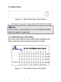
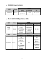
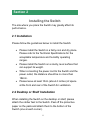
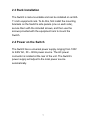
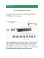
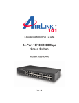
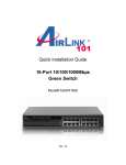
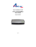
Quick Installation Guide
24-Port 10/100Mbps
Green Switch
Model# ASW324v2
Ver. 1A
Trademarks
Copyright © 2011 Airlink101®
Airlink101® is a registered trademark. All other trademarks
belong to their respective proprietors.
Copyright Statement
No part of this publication may be reproduced in any form or
by any means or used to make any derivative such as
translation, transformation, or adaptation without permission
from Phoebe Micro, Inc.
Preface
FCC Warning
This device has been tested and found to comply with limits
for Class A digital device, pursuant to Part 15 of the FCC
Rules. These limits are designed to provide reasonable
protection against harmful interference when the equipment
is operated in a commercial environment. This equipment
generates, uses and can radiate radio frequency energy
and, if not installed and used in accordance with the user’s
manual, may cause interference in which case the user will
be required to correct the interference at his own expense.
CE Mark Warning
This is a Class A product. In a domestic environment, this
product may cause radio interference in which case the
user may be required to take adequate measures.
1
Introduction
Congratulations on your purchase of the 24-Port 10/100Mbps
Green Switch! It is an easy-to-install network switch which
helps you to extend your network structure quickly and
reliably. The 24-Port 10/100Mbps Green Switch is designed
for energy saving, easy installation and high performance in
an environment where network traffic and the number of
users increase continuously. You can add other Ethernet
devices like computers, IP cameras, and Network Attached
Storage (NAS) onto your network quickly and easily. The
Green EEE (Energy Efficient Ethernet) technology of
ASW324v2 automatically reduces the power consumption
when any connected port is detected inactive (idle or
cable-unplugged) and it intelligently allocates less power to
any port that connects with an Ethernet cable shorter than
20m (66 ft)*.
Before you start installation, please check the package
contents:
Package Contents:
• 24-Port 10/100Mbps Green Switch
• Power Cord
• Quick Installation Guide
• Brackets and Screws
2
Section 1
Hardware Description
1.1 Hardware Interface
•
•
24 x Port 10/100Mbps auto-negotiation RJ45 port
All ports support auto MDI/MDIX, no need to use
cross-over cables
1.2 Panel
1.2.1 Front Panel
The front panel of the Switch consists of LED indicators, and
24 10/100Mbps ports. The figure below shows the front panel
of the Switch.
Figure 1-1 Front Panel View of the Switch
•
•
10/100Mbps Ports (Port 1~24): These ports support
10/100Mbps, and can operate in Half/Full Duplex transfer
modes. These ports also support automatic MDI/MDI-X
crossover detection, offering true “plug and play” function.
LED Indicators: Comprehensive LED indicators display
the status of the Switch and the network (see Section
1.2.3).
3
1.2.2 Rear Panel
Figure 1-2 Rear Panel View of the Switch
•
AC Power Connector: Supports AC 100~240V, 50~60Hz.
NOTE:
Do not cover or put anything on or surrounding the Switch
while the Switch is operating.
1.2.3 LED indicators information
The front panel LEDs provide instant status feedback and
help monitoring and troubleshooting when needed.
Figure 1-3 Front Panel View of the Switch
4
•
•
POWER: Power Indicator
LED
Color
POWER
Green
Solid
The Switch is
power-on
Status
Blinking
Off
N/A
No power
Port 1~24 10/100Mbps Status LEDs
LED
Color
LINK/
ACT
Green
LED
Color
10/ 100M
Green
Solid
No activities
on the
10/100Mbps
Ethernet
network
Solid
The
respective
port is
connected to
the
10/100Mbps
Ethernet
network
5
Status
Blinking
The port is
transmitting
or receiving
data at
10/100Mbps
Status
Blinking
No link
N/A
The
respective
port is
connected
to the slow
Ethernet
network
Off
Off
Section 2
Installing the Switch
The site where you place the Switch may greatly affect its
performance.
2.1 Installation
Please follow the guidelines below to install the Switch:
•
•
•
•
Please install the Switch in a fairly cool and dry place.
Please refer to the Technical Specifications for the
acceptable temperature and humidity operating
ranges.
Please install the Switch on a sturdy, level surface that
can support its weight.
When connecting the power cord to the Switch and the
power outlet, the distance should be no more than
182cm.
Please leave at least 10cm (about 4 inches) of space
at the front and rear of the Switch for ventilation.
2.2 Desktop or Shelf Installation
When installing the Switch on the desktop or shelf, please
attach the rubber feet to the Switch. Peel off the protective
paper on the pads and attach them to the bottom of the
Switch (one at each corner).
6
2.3 Rack Installation
The Switch is rack-mountable and can be installed on an EIA
11-inch equipment rack. To do this, first install the mounting
brackets on the Switch’s side panels (one on each side),
secure them with the included screws, and then use the
screws provided with the equipment rack to mount the
Switch.
2.4 Power on the Switch
The Switch has a universal power supply ranging from 100V
to 240V AC, 50 ~ 60Hz power source. The AC power
connector is located at the rear of the unit. The Switch’s
power supply will adjust to the local power source
automatically.
7
Section 3
Connecting the Switch
This section describes how to connect the Switch to your
10/100Mbps Ethernet network.
Your network device (i.e. computer, switch, IP Camera, VoIP)
can be connected to any port of the Switch via a two-pair
UTP Category 5 Cable. If the LED indicators do not light up
after making a proper connection, check your network device,
the cable, the Switch conditions and connections.
8
Section 4
Troubleshooting
1. Power LED is not on
•
Check if the power adapter is properly connected to the
power outlet. Make sure the power jack is firmly plugged
into the power socket of the switch.
2. Link/Activity is not lit when connect to 10/100Mbps device
•
Made sure that the network device attached to the switch
is turned ON.
•
Check the network cable; make sure it is properly
connected to the switch and the network device.
•
Check the network cable; make sure the Ethernet cables
comply with the specifications described in Section 2.
9
Section 5
Technical Specifications
Standards
• IEEE 802.3 10BASE–T, IEEE 802.3u 100BASE–TX, IEEE
802.3x Flow Control and IEEE 802.3az(EEE – Energy
Efficient Ethernet)
Network Cables
• Ethernet (10Base-T): Cables: 2-pair UTP Cat. 3, 4, 5,
Twisted Pair (UTP). Up to 100m
• Fast Ethernet (100Base-T): 2-pair UTP Cat. 5, Twisted
Pair (UTP). Up to 100m
Ports
• 24 x 10/100Mbps Auto-Negotiation RJ45 Port
Access Method
• CSMA/CD
Transmission Method
• Store and Forward
Data Transfer Rate**
• Ethernet: 10/20Mbps – Half/Full-Duplex
• Fast Ethernet: 100/200Mbps – Half/Full Duplex
LED
• Power: Green
• Link/Activity: Link/Activity (Green)
10/100M (Green)
Rack Mount
• 11-Inch Rack-Mountable with mounting kits
Dimensions
10
• 280mm x 165mm x 45mm (LxWxH)
Weight
• 1400g (3 lb)
Physical and Environmental
• Power Input: 100~240V AC, 50~60Hz
• Operation Temperature: 0 °C ~ 40°C(32°F ~ 104°F)
• Storage Temperature: -20°C ~ 70°C(-4°F ~ 158°F)
• Humidity: 5% ~ 90% RH, non-condensing
Certification
• FCC, CE
11
Section 6
Technical Support
E-mail: [email protected]
Toll-Free: 1-888-746-3238*
Web Site: www.airlink101.com
* Free Voice Technical Support is only available within the hardware warranty
(1-Year Limited Warranty from the date of purchase). Customer is required to
provide invoice as purchase evidence.
**Network conditions and environmental factors as well as network overhead can
lower actual data throughput rate.
Copyright © 2011 AirLink101®. All rights reserved. AirLink101, the stylized
AirLink101® logo, specific product designations, and all other words and logos
that are identified as trademarks and/or service marks are, unless noted
otherwise, the trademarks and service marks of AirLink101®. All other product or
service names are the property of their respective holders. AirLink101 products
are protected under numerous U.S. and foreign patents and pending applications,
mask work rights, and copyrights.
12