Transcript
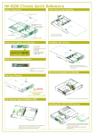
IW-R300 Chassis Quick Reference
Major Components
5.25”, 3.5” & Slim ODD Front
Cover Opening
Screw-less Top Cover
60mm Exhaust Fan (Optional)
Single PSU
Front Control & Indicators
3
Slim ODD bay
80mm Front Fan
Standard 5.25” bay
Standard 3.5” bay
Front Panel Controls and Indicators
A: USB 2.0 Port
B: System Reset Button
C: System HDD Activity LED
D: Power LED
H DC F G E B
1. Release four screws to remove the
whole cage set out of the chassis.
2. Remove two screws on each side for
taking out the front cover opening
bracket.
3. Remove two screws then move back
and take out the cover bracket.
2
1
2
Installing 5.25”, 3.5” & Slim ODD Devices
A
F: LAN1 LED
G: LAN2 LED
H: Power Button
2
1
1. Slide in and attach 2pcs on each slide
screws 5.25” or 3.5” device.
2 x 60mm Rear Fans (Optional)
7 PCI Slots
3
2
2. Attach with two screws
metal bracket.
assembly set.
Optional Redundant PSU
Area I/O
3.5” Device Cage & Trays Installing
Hard Drive
Top Cover Opening
4
CAUTION
Press
This unit must be operated
with the chassis
TOP COVER installed to
ensure proper cooling.
4
2
1
4
3
Press
1. Release two screws to remove the cage out for 3.5” HDD device Installation.
2. Release one screw only to remove the HDD tray.
3. Release two screws to remove the HDD tray.