Download Moog Videolarm SDW16C
Transcript
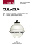
© 2009, Videolarm, Inc. All Rights Reserved SDW12 & SDP12 © 2009, Videolarm, Inc. All Rights Reserved Outdoor/ Indoor Fixed Dome Housing www.videolarm.com Installation and Operation Instructions for the following models: SDP12C 12” Outdoor/Indoor dome housing with pendant mount, clear dome, (1) fixedcamera bracket SDW12C 12” Outdoor/Indoor dome housing with wall mount, clear dome, (1) fixed camera bracket SDP12T 12” Outdoor/Indoor dome housing with pendant mount, tinted dome, (1) fixedcamera bracket SDW12T 12” Outdoor/Indoor dome housing with wall mount, tinted dome, (1) fixed camera bracket SDP12CHB 12” Outdoor dome housing with pendant mount, clear dome, 24Vac input,heater/blower/thermostat, (1) fixed camera bracket SDW12CHB 12” Outdoor dome housing with wall mount, clear dom, 24Vac input, heater/ blower/ thermostat, (1) fixed camera bracket Before attempting to connect or operate this product, please read these instructions completely. CERTIFIED 81-IN5383 01-15-2009 IMPORTANT SAFEGUARDS 1 Read these instructions. 2 Keep these instructions. 3 Heed all warnings 4 Follow all instructions. 5 Do not use this apparatus near water. 6 Clean only with damp cloth. 7 Do not block any of the ventilation openings. Install in accordance with the SAFETY PRECAUTIONS CAUTION RISK OF ELECTRIC SHOCK DO NOT OPEN manufacturers instructions. 8 Cable Runs- All cable runs must be within permissible distance. 9 Mounting - This unit must be properly and securely mounted to a supporting structure capable of sustaining the weight of the unit. Accordingly: a. The installation should be made by a qualified installer. b. The installation should be in compliance with local codes. c. Care should be exercised to select suitable hardware to install the unit, taking into account both the composition of the mounting surface and the weight of the unit. 10 Do not install near any heat sources such as radiators, heat registers, stoves, or other apparatus ( including amplifiers) that produce heat. 11 Do not defeat the safety purpose of the polarized or grounding-type plug. A polarized plug has two blades with one wider than the other. A grounding type plug has two blades and a third grounding prong. The wide blade or the third prong are provided for your safety. When the provided plug does not fit into your outlet, consult an electrician for replacement of the obsolete outlet. 12 Protect the power cord from being walked on or pinched particularly at plugs, convenience receptacles, and the point where they exit from the apparatus. 13 Only use attachment/ accessories specified by the manufacturer. 14 Use only with a cart, stand, tripod, bracket, or table specified by the manufacturer, or sold with the apparatus. When a cart is used, use caution when moving the cart/ apparatus combination to avoid injury from tip-over. 15 Unplug this apparatus during lighting storms or when unused for long periods of time. 16 Refer all servicing to qualified service personnel. Servicing is required when the apparatus has been damaged in any way, such as power-supply cord or plug is damaged, liquid has been spilled of objects have fallen into the apparatus, the apparatus has been exposed to rain or moisture, does not operate normally, or has been dropped. Be sure to periodically examine the unit and the supporting structure to make sure that the integrity of the installation is intact. Failure to comply with the foregoing could result in the unit separating from the support structure and falling, with resultant damages or injury to anyone or anything struck by the falling unit. UNPACKING Unpack carefully. Electronic components can be damaged if improperly handled or dropped. If an item appears to have been damaged in shipment, replace it properly in its carton and notify the shipper. Be sure to save: 1 The shipping carton and packaging material. They are the safest material in which to make future shipments of the equipment. 2 These Installation and Operating Instructions. SERVICE If technical support or service is needed, contact us at the following number: TECHNICAL SUPPORT AVAILABLE 24 HOURS 1 - 800 - 554 -1124 CAUTION: TO REDUCE THE RISK OF ELECTRIC SHOCK, DO NOT REMOVE COVER ( OR BACK). NO USER- SERVICEABLE PARTS INSIDE. REFER SEVICING TO QUALIFIED SERVICE PERSONNEL. The lightning flash with an arrowhead symbol, within an equilateral triangle, is intended to alert the user to the presence of non-insulated “dangerous voltage” within the product’s enclosure that may be of sufficient magnitude to constitute a risk to persons. Este símbolo se piensa para alertar al usuario a la presencia del “voltaje peligroso no-aisIado” dentro del recinto de los productos que puede ser un riesgo de choque eléctrico. Ce symbole est prévu pour alerter I’utilisateur à la presence “de la tension dangereuse” non-isolée dans la clôture de produits qui peut être un risque de choc électrique. Dieses Symbol soll den Benutzer zum Vorhandensein der nicht-lsolier “Gefährdungsspannung” innerhalb der Produkteinschließung alarmieren die eine Gefahr des elektrischen Schlages sein kann. Este símbolo é pretendido alertar o usuário à presença “di tensão perigosa non-isolada” dentro do cerco dos produtos que pode ser um risco de choque elétrico. Questo simbolo è inteso per avvertire I’utente alla presenza “di tensione pericolosa” non-isolata all’interno della recinzione dei prodotti che può essere un rischio di scossa elettrica. The exclamation point within an equilateral triangle is intended to alert the user to presence of important operating and maintenance (servicing) instructions in the literature accompanying the appliance. Este símbolo del punto del exclamation se piensa para alertar al usuario a la presencia de instrucciones importantes en la literatura que acompaña la aplicación. Ce symbole de point d’exclamation est prévu pour alerter l’utilisateur à la presence des instructions importantes dans la littérature accompagnant l’appareil. Dieses Ausruf Punktsymbol soll den Benutzer zum Vorhandensein de wichtigen Anweisungen in der Literatur alarmieren, die das Gerät begleitet. Este símbolo do ponto do exclamation é pretendido alertar o usuário à presença de instruções importantes na literatura que acompanha o dispositivo. Questo simbolo del punto del exclamaton è inteso per avvertire l’utente alla presenza delle istruzioni importanti nella letteratura che accompagna l'apparecchio. LIMITEDWARRANTY FOR VIDEOLARM INC. PRODUCTS VIDEOLARMINC. warrantsthis Productto be free from defectsin materialor workmanship,as follows: PRODUCTCATEGORY PARTS LABOR All Enclosures and Electronics Five (5) Years Five (5) Years Pan/Tilts Three (3) Years **6 months if used in autoscan Three (3) Years **6 months if used in autoscan /tour operation Poles/PoleEvators Three (3) Years /tour operation Three (3) Years Warrior/Q-View/I.R. Illuminators Five (5) Years Five (5) Years Five (5) Years SView Series Five (5) Years **6 months if used in autoscan **6 months if used in autoscan /tour operation /tour operation Controllers Five (5) Years Five (5) Years Power Supplies Five (5) Years Five (5) Years Accessory Brackets Five (5) Years Five (5) Years During the labor warranty period, to repair the Product, Purchaser will either return the defective product, freight prepaid, or deliver it to Videolarm Inc. an equal degree of protection with a Decatur GA. The Product to be repaired is to be returned in either its original carton or a similar package RMA # (Return Materials Authorization number) displayed on the outer box or packing slip. To obtain a RMA# you must contact our Technical Support Team at 800.554.1124, extension 101. Videolarm will return the repaired Product freight prepaid to Purchaser. Videolarm is not obligated to provide Purchaser with a substitute unit during the warranty period or at any time. After the applicable warranty period, Purchaser must pay all labor and/or parts charges. The limited warranty stated in these product instructions is subject to all of the following terms and conditions: TERMS AND CONDITIONS 1. NOTIFICATIONOF CLAIMS: WARRANTYSERVICE:If Purchaser believes that the Product is defective in material or workmanship, then written notice with an explanation of the claim shall be given promptly by Purchaser to Videolarm but all claims for warranty service must be made within the warranty period. If after investigation Videolarm determines that the reported problem was not covered by the warranty, Purchaser shall pay Videolarm for the cost of investigating the problem at its then prevailing per incident billable rate. No repair or replacement of any Product or part thereof shall extend the warranty period as to the entire Product. The warranty on the repaired part only shall be in for a period of ninety (90) days following the repair or replacement of that part or the remaining period of the Product parts warranty, whichever is greater. 2. EXCLUSIVE REMEDY: ACCEPTANCE:Purchaser’s exclusive remedy and Videolarm’s sole obligation is to supply (or pay for) all labor necessary to repair any Product found to be defective within the warranty period and to supply, at no extra charge, new or rebuilt replacements for defective parts. 3. EXCEPTIONS TO LIMITED WARRANTY: Videolarm shall have no liability or obligation to Purchaser with respect to any Product requiring service during the warranty period which is subjected to any of the following: abuse, improper use: negligence, accident, lightning damage or other acts of God (i.e., hurricanes, earthquakes), failure of the end-user to follow the directions outlined in the product instructions, failure of the end-user to follow the maintenance procedures recommended by the International Security Industry Organization, written in product instructions, for regular or recommended in the service manual for the Product. Furthermore, Videolarm shall have no liability where a schedule is replacement or maintenance or cleaning of certain parts (based on usage) and the end-user has failed to follow such schedule; attempted repair by personnel; operation of the Product outside of the published environmental and electrical parameters, or if such Product’s original (trademark, serial number) markings have been defaced, altered, or removed. Videolarm excludes from warranty coverage Products sold AS IS and/or WITH ALL FAULTS and excludes used Products which have not been sold by Videolarm to the Purchaser. All software and accompanying documentation furnished with, or as part of the Product is furnished “AS IS” (i.e., without any warranty of any kind), except where expressly provided otherwise in any documentation or license agreement furnished with the Product. 4. PROOF OF PURCHASE: The Purchaser’s dated bill of sale must be retained as evidence of the date of purchase and to establish warranty eligibility. DISCLAIMEROF WARRANTY EXCEPT FOR THE FOREGOING WARRANTIES, VIDEOLARM HEREBY DISCLAIMS AND EXCLUDES ALL OTHER WARRANTIES, EXPRESS OR IMPLIED, INCLUDING, BUT NOT LIMITED TO ANY AND/OR ALL IMPLIED WARRANTIES OF MERCHANTABILITY, FITNESS FOR A PARTICULAR PURPOSE AND/OR ANY WARRANTY WITH REGARD TO ANY CLAIM OF INFRINGEMENT THAT MAY BE PROVIDED IN SECTION 2-312(3) OF THE UNIFORM COMMERCIAL CODE AND/OR IN ANY OTHER COMPARABLE STATE STATUTE. VIDEOLARM HEREBY DISCLAIMS ANY REPRESENTATIONS OR WARRANTY THAT THE PRODUCT IS COMPATIBLE WITH ANY COMBINATION OF NON-VIDEOLARM PRODUCTS OR NON-VIDEOLARM RECOMMENDED PRODUCTS PURCHASER CHOOSES TO CONNECT TO PRODUCT. LIMITATION OF LIABILITY THE LIABILITY OF VIDEOLARM, IF ANY, AND PURCHASER’S SOLE AND EXCLUSIVE REMEDY FOR DAMAGES FOR ANY CLAIM OF ANY KIND WHATSOEVER, REGARDLESS OF THE LEGAL THEORY AND WHETHER ARISING IN TORT OR CONTRACT, SHALL NOT BE GREATER THAN THE ACTUAL PURCHASE PRICE OF THE PRODUCT WITH RESPECT TO WHICH SUCH CLAIM IS MADE. IN NO EVENT SHALL VIDEOLARM BE LIABLE TO PURCHASER FOR ANY SPECIAL, INDIRECT, INCIDENTAL, OR CONSEQUENTIAL DAMAGES OF ANY KIND INCLUDING, BUT NOT LIMITED TO, COMPENSATION, REIMBURSEMENT OR DAMAGES ON ACCOUNT OF THE LOSS OF PRESENT OR PROSPECTIVE PROFITS OR FOR ANY OTHER REASON WHATSOEVER. ! Electrical Specifications Power 24VAC Class 2 Only SDW12 English 24 VAC 3.33Amps Total Power: 52 Watts Accessories: Heater: 50 Watts/Blower: 2 Watts Camera Power: Not Supplied Tools Required: Housing Security Tool (provided) Molex Crimper 11-01-0197 (18-24 gauge wire) Español 24 VAC 3.33 amperios Energía Total: 52 vatios Accesorios: Calentador: 50 Watts/Blower: 2 vatio Energía De la Cámara fotográfica: Not Supplied Las Herramientas Requirieron: Housing Security Tool (provided) Molex Crimper 11-01-0197 (18-24 gauge wire) Français 24 VCA 3.33 ampères Puissance Totale : 52 watts Accessoires : Réchauffeur : 50 Watts/Blower : 2 watts Puissance D'Appareil-photo : Not Supplied Les Outils besoin : Housing Security Tool (provided) Molex Crimper 11-01-0197 (18-24 gauge wire) Deutsch 24 VAC 3.33 Ampere Gesamtenergie: 52 Watt Zusatzgeräte: Heizung: 50 Watt/Blower: 2 Watt Kamera-Energie: Not Supplied Werkzeuge Erforderten: Housing Security Tool (provided) Molex Crimper 11-01-0197 (18-24 gauge wire) 24 VAC 3.33 ampères Poder Total: 52 watts Acessórios: Poder Da Câmera: Calefator: 50 Watts/Blower: 2 watt Not Supplied As Ferramentas Requereram: Housing Security Tool (provided) Portuguese Molex Crimper 11-01-0197 (18-24 gauge wire) Italiano Contents of Box 24 VAC 3.33 ampère Alimentazione Totale: 52 watt Accessori: Riscaldatore: 50 Watts/Blower: 2 watt Alimentazione Della Macchina fotografica: Not Supplied Attrezzi Richiesti: Housing Security Tool (provided) Molex Crimper 11-01-0197 (18-24 gauge wire) PACKET 1 Wall Mount Securely mount unit to wall or to appropriate adapter bracket. • Monte con seguridad la unidad a la pared o al soporte apropiado del adaptador. • Montez solidement l'unité au mur ou à la parenthèse appropriée d'adapteur. • Bringen Sie sicher Maßeinheit zur Wand oder zum passenden Adapterhaltewinkel an. • Monte firmemente a unidade à parede ou ao suporte apropriado do adaptador. • Monti saldamente l'unità alla parete o alla staffa adatta dell'adattatore. 2 If using conduit connect, connect to incoming conduit fitting. • Si usa el conducto conecte, conecte con la guarnición entrante del conducto. • Si à l'aide du conduit reliez, reliez à l'ajustage de précision entrant de conduit. • Wenn Sie Rohr verwenden, schließen Sie an, schließen Sie an ankommende Rohrbefestigung an. • Se usando a canalização conecte, conecte ao encaixe entrante da canalização. • Se per mezzo del condotto colleghi, colleghi al montaggio ricevuto del condotto. 3 4 Open access door to access power and control connectors. Make wire connection as they are required for your needs. • Abra la puerta de acceso en los conectadores de la energía y de control del acceso. • Ouvrez la porte d'accès aux connecteurs de puissance et de commande d'accès. • Öffnen Sie Zugang zur Zugang Energie und zu den Geräteanschlüssen. • Abra a porta de acesso aos conectores do poder e de controle do acesso. • Apra il portello di accesso ai connettori di alimentazione e di controllo di accesso. • Haga la conexión del alambre como se requieren para sus necesidades. • Établissez le rapport de fil comme ils sont exigés pour vos besoins. • Stellen Sie Leitung Beziehung her, wie sie für Ihre Notwendigkeiten angefordert werden. • Faça a conexão do fio como são requeridos para suas necessidades. • Faccia il collegamento del legare come sono richiesti per i vostri bisogni. 1 5 Pendant Mount 2 6 Wrap Teflon tape around the pipe threads to ensure a tight seal. Securely mount bracket to wall. Pull wiring through bracket and position grommet as shown. • Con seguridad soporte del montaje a emparedar. Tire del cableado a través del soporte y del ojal de la posición según lo demostrado. • Solidement parenthèse de bâti à murer. Tirez le câblage par la parenthèse et le canon isolant de position comme montré. • Sicher Einfassung Haltewinkel wall. Ziehen Sie Verdrahtung durch Haltewinkel und Position Gummimuffe, wie gezeigt. • Firmemente suporte da montagem a wall. Puxe a fiação através do suporte e do ilhó da posição como mostrado. • Saldamente staffa del supporto da wall. Tiri i collegamenti tramite la staffa ed il gommino di protezione di posizione come indicato. 3 7 TM • La cinta del Teflon del abrigo alrededor de la pipa rosca para asegurar un sello apretado. • La bande de teflon d'enveloppe autour de la pipe filète pour assurer un joint serré. • Verpackung Teflonklebeband um das Rohr verlegt, um eine feste Dichtung sicherzustellen. • A fita adesiva do Teflon do envoltório em torno da tubulação enfía para assegurar um selo apertado. • Il nastro del Teflon dell'involucro intorno al tubo filetta per accertare una guarnizione stretta. 4 8 Screw the coupling onto the pipe threads until it is hand tight. • Atornille el acoplador sobre los hilos de rosca de la pipa hasta que es mano firmemente. • Vissez le couplage sur les fils de pipe jusqu'à ce que ce soit main fortement. • Schrauben Sie die Koppelung auf die Rohrgewinde, bis es Hand fest ist. • Parafuse o acoplamento nas linhas da tubulação até que esteja mão firmemente. • Avviti l'accoppiamento sui filetti del tubo fino a che non sia fortemente mano. Screw the (2) bolts into the coupling. • Atornille (2) los pernos en el acoplador. • Vissez (2) les boulons dans l'accouplement. • Schrauben Sie die (2) Schraubbolzen in die Koppelung. • Parafuse (2) os parafusos no acoplamento. • Avviti (2) i bulloni nell'accoppiamento. 5 9 Loop the lanyard over the set screw to temporarily hold housing. • Coloque el acollador sobre el tornillo de presión para celebrar temporalmente la cubierta. • Faites une boucle la lanière au-dessus de la vis de réglage pour tenir temporairement le logement. • Schlingen Sie die Abzuglinie über der Klemmschraube, um Gehäuse vorübergehend zu halten. • Dê laços no colhedor sobre o parafuso de fixação para prender temporariamente a carcaça. • Colleghi la cordicella in circuito sopra la vite di arresto temporaneamente per tenere l'alloggiamento. 7 11 Undo the lanyard, pull housing up and twist secure with the locking bolt and washers. 6 10 Make the appropriate wiring connections from the dome to the gooseneck. • Haga las conexiones apropiadas del cableado de la bóveda al gooseneck. • Établissez les rapports appropriés de câblage à partir du dôme au col de cygne. • Stellen Sie die passenden Verdrahtung Beziehungen von der Haube zum gooseneck her. • Faça as conexões apropriadas da fiação da abóbada ao gooseneck. • Faccia i collegamenti adatti dei collegamenti dalla cupola al gooseneck. 8 12 Slide the grommet down over the coupling to prevent water from entering and complete the assembly. • Deshaga el acollador, tire de contener para arriba y tuerza seguro con el perno y las arandelas de fijación. • Resbale el ojal abajo sobre el acoplador para evitar que el agua entre y para terminar a la asamblea. • Défaites la lanière, tirez loger vers le haut et tordez bloqué avec le boulon et les rondelles de fermeture. • Glissez le canon isolant vers le bas au-dessus de l'accouplement pour empêcher l'eau d'entrer et pour accomplir l'assemblée. • Annulieren Sie die Abzuglinie, ziehen Sie oben unterbringen und verdrehen Sie sicheres mit dem verriegelnschraubbolzen und den Unterlegscheiben. • Schieben Sie die Gummimuffe unten über der Koppelung, um zu verhindern, daß Wasser und die Versammlung durchzuführen hereinkommt. • Undo o colhedor, puxe abrigar acima e torça seguro com o parafuso e as arruelas travando. • Deslize o ilhó para baixo sobre o acoplamento para impedir que a água entre e para terminar o conjunto. • Undo la cordicella, tiri l'alloggio in su e torca sicuro con il bullone e le rondelle di bloccaggio. • Faccia scorrere il gommino di protezione giù sopra l'accoppiamento per impedire l'acqua entrare e per completare il complessivo. Wiring Color Code Power and Control Inputs (Outside of housing) 13 24k VAC Wiring Distances The following are the recommended maximum distances for 24 VAC with a 10% voltage drop (10% is generally the maximum allowable voltage drop for AC powered devices). POWER 1 Camera Power (24 VAC) Red 2 Camera Power (24 VAC) Orange 3 Accessory Power (24 VAC)(52 watts) Yellow 4 Accessory Power (24 VAC)(52 watts) reen CONTROL 1 R S -4 8 5 R XA Blu e 2 R S -4 8 5 R XB Vio le t 3 R S -4 8 5 TXA G ra y 4 R S -4 8 5 TXB Wh ite Power and Control Outputs (Inside of housing) POWER AND CONTROL LEADS 1 Camera Power (24 VAC) Red 2 Camera Power (24 VAC) 3 R S -4 8 5 R XA Blu e Orange 4 R S -4 8 5 R XB Vio le t 5 R S -4 8 5 TXA G ra y 6 R S -4 8 5 TXB Wh ite The unit is setup with (2) individual power inputs. 1. Accessory Power (yellow and green wire) 2. Camera Power (red and orange) If you wish to provide a single power transformer it is recommended that: 1. Be certain that you know the total power consumption of the housing Heater (25 watts) + Blower (1 watt) + power supply (not supplied) 2. Check the supplied wiring chart to be sure that you have the proper gauge wire for the distance that you intend to run your power wires. Total vA consumed 5.5 10 20 30 40 50 60 70 80 90 100 110 120 130 140 150 160 170 180 190 200 22 250 120 89 65 44 35 29 25 31 19 17 16 14 13 12 11 11 10 9 9 8 20 400 180 141 90 70 56 47 40 34 31 28 25 23 21 20 18 17 16 15 14 14 18 600 300 225 130 112 90 75 64 55 50 45 41 37 34 32 30 28 26 25 23 22 16 960 480 358 225 179 143 119 102 85 79 71 65 59 55 51 47 44 42 39 37 35 14 10 12 800 1300 571 905 1440 350 525 830 285 452 720 228 362 576 190 301 480 163 258 411 140 215 340 126 201 320 114 181 288 103 164 261 95 150 240 87 139 221 81 129 205 76 120 192 71 113 180 67 106 169 63 100 160 95 151 60 90 144 57 Maximum distance from transformer to load Wire Gauge 3. Bring power to the 3 and 4 position of the power connector (yellow and green wire) 4. Two jumpers are provided in the housing packet. Jumper from the 1 st position to the 3 rd position and from the 2 nd position to the 4 th position of the terminal block. Be careful not to short between the yellow and green wires. Add 2 jumpers for single power input 14 Housing Side Camera Side Assemble fixed camera bracket. • • • • Monte el soporte fijo de la cámara fotográfica. Assemblez la parenthèse fixe d'appareil-photo. Bauen Sie örtlich festgelegten Kamerahaltewinkel zusammen. Monte suporte fixo da câmera. • Monti la staffa fissa della macchina fotografica. 16 15 Attach fixed bracket to one of the (2) square holes. • Una el soporte fijo a una (2) de las perforaciones rectangulares. • Attachez la parenthèse fixe à un (2) des trous carrés. • Bringen Sie örtlich festgelegten Haltewinkel bis eine der (2) quadratischen Bohrungen an. • Una suporte fixo a um (2) dos furos quadrados. • Fissi la staffa fissa ad uno (2) dei fori quadrati. 17 Using security tool, attach dome to housing. Wipe surface if needed, with damp cotton cloth if needed. • Con la herramienta de la seguridad, una la bóveda a la cubierta. Limpie la superficie si está necesitado, con el paño húmedo del algodón si está necesitado. • En utilisant l'outil de sécurité, attachez le dôme au logement. Essuyez la surface si nécessaire, avec le tissu humide de coton si nécessaire. • Mit Sicherheit Werkzeug bringen Sie Haube zum Gehäuse an. Wischen Sie Oberfläche ab, wenn Sie, mit feuchtem Baumwolltuch benötigt werden, wenn Sie benötigt werden. • Usando a ferramenta da segurança, una a abóbada à carcaça. Limpe a superfície se necessitado, com o pano úmido do algodão se necessitado. • Per mezzo dell'attrezzo di sicurezza, fissi la cupola ad alloggiamento. Pulisca la superficie se avuto bisogno di, con il panno umido del cotone se avuto bisogno di. Complete wiring connection. Position camera to desired view angle. • Termine la conexión del cableado. Coloque la cámara fotográfica al ángulo deseado de la visión. • Accomplissez le raccordement de câblage. Placez l'appareilphoto à l'angle désiré de vue. • Führen Sie Verdrahtung Anschluß durch. Bringen Sie Kamera zu gewünschtem Ansichtwinkel in Position. • Termine a conexão da fiação. Posicione a câmera ao ângulo desejado da vista. • Completi il collegamento dei collegamenti. Posizioni la macchina fotografica sull'angolo voluto di vista. Replacement Parts List SDW12 1 2 3 8 4 5 6 10 7 9 Part Number Description 1 WM10 WALL MOUNT KIT 2 SD0190 SDW HOUSING GASKET 3 SDH012 HOUSING TOP FOR 12” HOUSING SDH016 HOUSING TOP FOR 16” HOUSING RPFD040 UPPER BRACKET ASSEMBLY 5 RP46PKH3063 SPACER KIT 6 RPFD050 PCBOARD 7 RPFD060 CAMERA BRACKET 8 RPFD072 25 WATT, 24 VAC HEATER 9 RPFD080 BLOWER 10 CWKFD2 24VAC COLD WEATHER KIT FOR OUTDOOR HOUSING 11 RCSD12 CLEAR REPLACEMENT CAP FOR POD/ SDW/MP 123 RCSD12T TINTED REPLACEMENT CAPSULE FOR SDW/MP 12 RCSD16 CLEAR REPLACEMENT CAPSULE SDW16/MP 163 RCSD16T TINTED REPLACEMENT CAPSULE SDW16/MP 163 4 11 Product Registration/Warranty Thank you for choosing Videolarm. We value your patronage and are solely committed to providing you with only the highest quality products available with unmatched customer service levels that are second-to-none in the security industry. Should a problem arise, rest assure that Videolarm stands behind its products by offering some of the most impressive warranty plans available: 3 Years on all Housings, Poles, Power Supplies, and Accessories and 5 Years on all camera systems (SView, QView, Warriors), and InfraRed Illuminators. Register Your Products Option 1: Online Option 2: Mail-In Take a few moments and validate your purchase with our Online Product Registration Form www.videolarm.com/productregistration.jsp at or complete and mail-in the bottom portion of this flyer. Register your recent Videolarm purchases and benefit from the following: • Simple and Trouble-Free RMA process • Added into customer database to receive product updates / news • Eliminate the need to archive original purchase documents: Receipts, Purchase Orders, etc… Main Contact Info Cut at the dotted Line Place in envelope, affix stamp and mail to: Videolarm ATTN: Warranty 2525 Park Central Ave. Decatur, GA 30035 First Name: Last Name: Professional Title: Company: Address 1: Address 2: City: State / Province/Country: Zip / Postal Code: Phone Number: Product Information Please Circle One: Name & Location of Company / Store where Purchased: (City, State, Country) Videolarm Product ID Product Description Serial # (Available only for Camera Systems, IR Illuminators, Wireless Devices) PO# E-mail Address: Business Personal
This document in other languages
- italiano: Moog Videolarm SDW16C