1
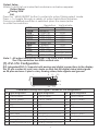
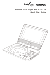
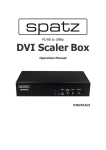
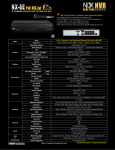
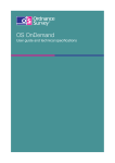
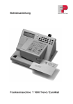
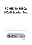
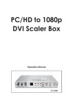
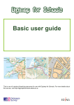
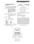
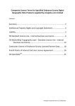
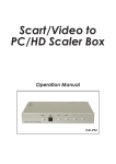
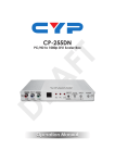
 MINISCALE Operation Manual
(1). Introduction
This professional video scaler is designed to convert Composite and S-Video
to high definition DVI resolutions. It handles video input from TV systems of
NTSC, PAL TV standards with many great features to enhance video
performance.
(2). Features
1.
Motion adaptive 3D Y/C separation comb filter
( for composite video input )
2. 3D( frame Based ) motion adaptive YNR/CNR noise reduction
( for Y/C video input )
3. Advanced 3D motion adaptive deinterlace
4. Automatic 2:2/3:2 film mode detection
5. Supports 50Hz to 60Hz frame rate conversion
6. Video quality improvement:
DCTI (Digital chroma transient improvement), DLTI (Digital luminance
transient improvement),
Black level extension.
7. Average picture level ( APL ), Automatic contrast limiter ( ACL ) function
supported.
8. OSD menu for picture quality adjustment.
9. Built-in 8-bit DAC for RGB or YPbPr output.
10. Front Panel and IR remote control.
11. Automatic NTSC/PAL video format detection and switching.
(3) This package includes
1. Video Scaler Unit.
2. DC adaptor
3. User Manual
4. Remote Control
1
(4). Operation Controls and Functions
Front Panel
POWER
INPUT
MENU
CV
SV
CM-1391 Video to DVI Scaler Box
1
2
3
4
5
6
1. Power button and LED indicator:
Press the button once to power on the unit, Press again to power off.
when the unit is powered on, one of the input LEDs will illuminate depending on
your last selection of input source before power off.
The factory default setting for the input is CV (composite video).
The green LED illuminates when composite video is selected.
The Yellow LED illuminates when S-Video is selected.
2. Input select button:
Press the button to select your desired input source between composite
video and S- Video.
3. IR Sensor: Infrad remote control sensor.
4. Menu/Enter: This button serves two purposes.
a. Press the button to bring up OSD main control menu as shown in the "OSD Operation".
b. To act as a "enter" key to enter sub menu of you selected item or adjust
value of the selected item.
5/6. +/- button: Press the button to move up or down the tick "V" to your
desired parameter. Or after a parameter is selected by pressing MENU/ENTER button,
press the button to alter the value of your selected parameter.
Rear Panel
DVI-I OUTPUT
INPUT
4
DC 5V
SV
CV
3
2
1
1. DC power jack: 5V 2A DC power input.
2. Composite Video: Use a Composite video cable to connect the composite video
output of the source equipment to this composite video(CV) input of the scaler.
3. S-Video: Use a S-Video cable to connect the S-Video output of the source
video equipment to this " S-Video" input on the back of the video scaler.
S-Video provides improved performance over composite video and is
recommended over composite.
4. DVI output: The CM-1391 can output a variety of PC and HDTV progressive
resolutions, in both digital and analog format through DVI-I connector.
Digital output: Connect CM-1391's digital DVI output to the DVI input of your
TV/display unit using a DVI to DVI cable .
Analog output: If you are to use CM-1391's analog output to connect to the
analog input of your PC or HDTV, you need to use a DVI to VGA adaptor to pull
out analog signal from the DVI-I connector . The DVI to VGA adaptor is then
connect to the VGA input of your display monitor through a VGA cable if
output is PC resolution, or connect to the YPbPr input of your HDTV through a
VGA to YPbPr/3 RCA adaptor cable if output is HDTV resolution.
Note: DVI to VGA adaptor is not included in the standard package,
and has to order separately.
2
(5). Output Format
a. The format of digital DVI output is digital RGB
for all resolutions.
-RGB
-RGB
-RGB
-RGB
-RGB
-RGB 1600 x 1200
UXGA
1920 x 1200
WUXGA -RGB
HDTV (RGBHV)
1080p-RGB
1920x1080p follow input source
1080i-RGB
1920x1080i follow input source
follow input source
1280X720
720p-RGB
576p-RGB
720X576
480p-RGB
720X480
b. The format for analog PC output is RGB and for
analog HD output is YPbPr.
-RGB
-RGB
-RGB
-RGB
-RGB
-RGB 1600 x 1200
UXGA
1920 x 1200
WUXGA -RGB
HDTV (YPbPr)
1080p-RGB
1920x1080p follow input source
1080i-RGB
1920x1080i follow input source
follow input source
1280X720
720p-RGB
576p-RGB
720X576
480p-RGB
720X480
(6). OSD Operation
After power on the unit , press the menu button to bring up the main menu
page as below:
Main Menu
Picture adj.
Output Setup
Exit
Use +,- button to move "V" to your desired parameter, then press MENU/ENTER
to enter into sub-menu of your selected parameter.
Picture Adjust
When Picture Adjust is selected a sub menu as below comes up.
Default
Range
Bright
Contrast
Color
Tint
Sharp
Default
Exit
16
16
16
16
05
OK
1-31
1-31
1-31
1-31
1-19
USE +,- to move the tick (V) to your desired adjust item, Press the Menu/Enter
to confirm your selection.
At this point, the selected parameter will turn red, and you can use +,- to increase
or decrease the value of the parameter.
When adjustment is complete, Press "Menu" to leave the parameter. Move the tick "V"
to "Exit", then press menu/enter to exit.
3
Output Setup
When Output Set up is selected a submenu as below appears:
Output Setup
Timing XGA
Exit
Press the " MENU/ENTER" button to enter into output timing select mode.
Press +,- to toggle through a variety of output resolutions as below.
Once your desired resolution is selected. press the menu/enter
to enter the resolution.
Resolution Vertical rate
60Hz
VGA
640x480
60Hz
SVGA
800x600
60Hz
XGA
1024x768
60Hz
WXGA
1280x768
60Hz
SXGA
1280x1024
60Hz
UXGA
1600x1200
60Hz
WUXGA
1920x1200
50Hz
480p
720x480
60Hz
576p
720x576
follow input source
720p
1280x720
1080i
1920x1080i follow input source
1080p
1920x1080p follow input source
Note: 1. All output resolutions except 576p have 60Hz vertical rate,
The 576p resolution has 50Hz vertical rate.
(7). DVI-I Pin Configuration
DVI-Integrated(DVI-I): Supports both analog and digital connections to the display.
This 29-pin connector can carry single or dual-link all-digital video/data signals
on 24 pins and uses 5 pins to carry analog video/data signals and ground.
1
8
C1
C2
9
C5
17
24
C3
C4
Combined Analog and Digital Connector Pin Assignments
Pin Signal Assignment
Pin Signal Assignment
Pin Signal Assignment
1
T.M.D.S Data2-
9
T.M.D.S Data1-
17
T.M.D.S Data0-
2
T.M.D.S. Data2+
10
T.M.D.S. Data1+
18
T.M.D.S. Data0+
3
T.M.D.S. Data2 Shield
11
T.M.D.S. Data1 Shield
19
T.M.D.S. Data0 Shield
4
N.C.
12
N.C.
20
N.C.
5
N.C.
13
N.C.
21
N.C.
6
DDC Clock
14
+5V Power
22
T.M.D.S. Clock Shield
7
DDC Data
15
Ground (Return for +5V, Hsync, and Vsync)
23
T.M.D.S. Clock+
8
Analog Vertical Sync
16
Hot Plug Detect
24
T.M.D.S. Clock-
C3
Analog Blue
C1
Analog Red
C2
Analog Green
C4
Analog Horizontal Sync
C5
Analog Ground(Analog R,G,&B return)
4
(8). Remote Control
1. Display: Press the button to display input source
and output resolution on the screen.
2. Power: Power ON/OFF button.
3. VGA~1080p: Press to select your desired
output resolution.
4. Picture: Press the button to enter picture
adjust submenu. Use +,- button to move
cursor (V) up/down to your desired
parameter, press "Picture" again to
confirm.
5. +/-: Press to move up/down the cursor (V)
to your desired parameter,or press to
increase/decrease the setting value.
4
6. Reset: Press to reset all setting back to
factory default value.
7. Exit: To exit OSD.
6
8. Video: Press the button to select
composite video input.
9. SVideo: Press the button to select
SVideo input.
3
VGA
1
SVGA
WXGA
SXGA
XGA
UXGA
576p
WUXGA
720p
1080i
1080p
PICTURE
-
+
5
RESET
EXIT
Video@1Vp-p, 75 ohm, Y@1 Vp-p, 75 ohm
Color@ 0.7 Vp-p, 75 ohm
Output Format
Digital RGB
DVI-I Connector
Bit stream
Weight(g)
400
Dimensions(mm)
125(W) x 123(D) x 30(H)
Operating Temperature
0°C~40°C
Silkscreen Color
Process Blue
Output Signal Specifications
-RGB
-RGB
-RGB
-RGB
-RGB
-RGB 1600 x 1200
UXGA
1920 x 1200
WUXGA -RGB
1080p-RGB
1080i-RGB
720p-RGB
576p-RGB
480p-RGB
SVIDEO
9
Input Signal Levels
Output Connector
VIDEO
8
480p
(9). Specifications
Output Singnal
2
HDTV (RGBHV)
1920x1080p follow input source
1920x1080i follow input source
follow input source
1280X720
720X576
720X480
7
CR-58