1
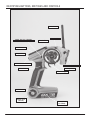
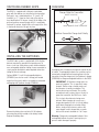
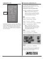
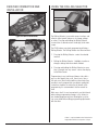
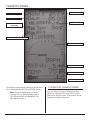
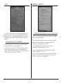
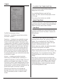
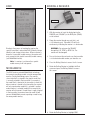
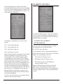
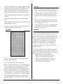
®
DSM Sport System with Integrated Telemetry
Table of Contents
Introduction.............................................................................................................................................3
Contents..................................................................................................................................................3
ModelMatch/Binding...............................................................................................................................3
System Features.......................................................................................................................................3
Identifying Buttons, Switches and Controls.............................................................................................4
Switching Rubber Grips...........................................................................................................................5
Installing the Batteries..............................................................................................................................5
Charging..................................................................................................................................................5
Steering Rate............................................................................................................................................6
Receiver Compatibility.............................................................................................................................6
Receiver Connection and Installation.......................................................................................................7
Using the Rolling Selector.......................................................................................................................7
Main Screen.............................................................................................................................................8
Telemetry Screen......................................................................................................................................9
List.........................................................................................................................................................10
Model Select..........................................................................................................................................10
Model Name..........................................................................................................................................11
Model Reset...........................................................................................................................................11
Travel.....................................................................................................................................................12
Exponential............................................................................................................................................13
Reverse..................................................................................................................................................14
Sub Trim................................................................................................................................................14
Timer......................................................................................................................................................15
Bind.......................................................................................................................................................16
ModelMatch...........................................................................................................................................16
Binding a Receiver.................................................................................................................................16
Failsafe..................................................................................................................................................17
Throttle Punch.......................................................................................................................................17
AUX Setting...........................................................................................................................................18
Telemetry Settings..................................................................................................................................19
System...................................................................................................................................................22
Installing the Telemetry Sensors in Your Vehicle...................................................................................23
General Notes........................................................................................................................................25
Tips on Using 2.4GHz Systems.............................................................................................................26
General Information...............................................................................................................................27
Warranty Information.............................................................................................................................27
Compliance Information for the European Union...................................................................................29
Instructions for Disposal of WEEE by Users in the European Union......................................................29
2
SPEKTRUM DX3S USER GUIDE
ModelMatch/Binding
The DX3S features patent pending ModelMatch.
ModelMatch prevents a model from being operated when
the wrong model memory is selected. If the wrong model
memory is selected the receiver simply won’t respond to
the transmitter.
Introduction
Spektrum’s DX3S features an integrated telemetry system
providing accurate speed/rpm, temperature and voltage
readings. Featuring DSM 2.4GHz technology, the DX3S
offers sophisticated software combined with an easy-touse one-touch Rolling Selector making programming
quick and easy. Spektrum technology offers a bulletproof
radio link that’s immune to internal (noisy motors/ ESCs,
etc.) and external interfering sources. No longer will you
have to wait for a frequency or worry about someone else
being on the same channel. With Spektrum when you’re
ready to race there’s nothing stopping you!
Contents
The DX3S radio system is supplied with the following:
•
•
•
•
•
•
•
•
•
•
•
•
•
•
•
DX3S transmitter
SR3300T receiver (SPMSR3300T)
SR300 receiver (SPMSR300)
Bind plug (SPM6802)
4 AA Alkaline batteries
Receiver AA battery holder
Switch harness
Grip Set (SPM9006)
Head Temperature Sensor (SPM1450)
Battery/Motor Temperature Sensor (SPM1451)
RPM Sensor (SPM1452)
Sensor Mount Hardware .21-.26 (SPM1501)
Sensor Mount Hardware .12-.15 (SPM1502)
Sensor Mount Hardware Electrics (SPM1503)
Telemetry RPM Sticker (SPM1512)
It’s necessary to program the receiver to a specific
model memory (called binding) so that the receiver
will only recognize and respond to that specific model
memory. See Page 16 for specific details on Binding and
ModelMatch.
System Features
• Integrated Telemetry
• One-touch easy-to-use programming
• Internal and programmable Up or Down timers
• 128x64 high resolution dot-matrix screen
• 10-model memory
• Travel adjust
• Exponential
• Throttle punch
• Steering mix
• Expert and standard modes
Dodge and HEMI are trademarks of
Chrysler LLC. Dodge Ram and its trade
dress are used under license by Horizon
Hobby, Inc. ©Chrysler LLC 2009.
SPEKTRUM DX3S USER GUIDE
3
Identifying Buttons, Switches and Controls
Antenna
Steering Trim
Switch - Aux. Ch. 2-Position
Throttle Trim
LCD Screen
Rolling Selector
Remote Start Button
Timer Button
Steering Rate Knob
Steering Wheel
Throttle Trigger
On/Off Switch
Charge Jack
(on back)
4
Battery Door
(on bottom)
SPEKTRUM DX3S USER GUIDE
Switching Rubber Grips
The DX3S is supplied with 3 different-sized rubber
grips with the medium-size installed on the transmitter.
Each grip’s size is identified with an “S” (small), “M”
(medium), or “L” (large) on the inside of the grip for
easy identification. To remove, simply lift the edge of the
grip and continue around the grip until it is completely
removed. To replace, align the tabs of the grip to the slots
in the handle and press the grip in place.
Charging
Charger Pigtail for Transmitter
BLACK TO POSITIVE
BLACK W/WHITE STRIPE TO NEGATIVE
Spektrum Transmitter Charge Jack Polarity
-
+
Installing the Batteries
The DX3S radio system is supplied with 4 AA alkaline
batteries required for operation that provide over 16
hours of run time. Many drivers prefer alkaline batteries
over rechargeable batteries finding it more convenient to
simply replace the batteries when depleted rather than
taking the time to recharge.
Optional NiMH 1.2-volt AA rechargeable batteries
(SPM9525) can also be used. A charge jack located
opposite of the on/off switch is provided for convenient
recharging with Spektrum charger SPM9526.
Remove the battery door and install 4 AA batteries
observing the polarity marked on the battery holder.
Replace the battery door.
SPEKTRUM DX3S USER GUIDE
A charging jack is located on the opposite side of the on/
off switch. If rechargeable batteries are used they can be
conveniently charged without removing them from the
transmitter using the charge jack. Use Spektrum’s charger
(SPM9526) to charge rechargeable batteries in the DX3S.
IMPORTANT: All Spektrum charge jacks are
center-pin negative. This is opposite of many
chargers. Before using a charger, make sure
the connector is center-pin negative. This
can be done using a voltmeter. Also, unlike
conventional radio systems that use 8 cells to
power the transmitter, the DX3S uses 4 cells.
This is due to the electronics being more
efficient. When charging, be sure to use a
charger designed for 4 cells (a 4.8-volt battery
pack) when charging the transmitter. Many
drivers simply make a harness and use the
same charger used to charge their car packs
but turn the current rate down to 1 to 2 amps.
Warning: Charge only rechargeable batteries. Nonrechargeable batteries may burst causing injury to
persons and/or damage to property.
5
Steering Rate
Receiver Compatibility
The DX3S features DSM technology and is now
compatible with Spektrum DSM and DSM2 surface
receivers and the marine receiver.
Compatible Spektrum Receivers
The DX3S is compatible with the following receivers.
Steering
Rate
Note: The DX3S operates in either 11ms
(default) or 16.5ms frame rates. 5.5ms frame
rate is not available on the DX3S. See page 22
for more information on frame rates.
DSM
SR300 - 3-channel Sport - SPMSR300
SR3000 - 3-channel Standard - SPM1200
SR3001 - 3-channel Pro - SPM1205
Steering rate (also known as dual rate), allows on-the-fly
steering travel adjustments to be made using the steering
rate knob. Steering rate limits the amount of travel of the
steering servo. The steering rate cannot be greater than
100% and will never exceed the amount of steering travel
set in the travel screen.
SR3300T - 3-channel with built-in telemetry - SPMSR3300T
SR3500 - 3-channel Micro Race - SPM1210
Note: The SR3000HRS (SPM1202) receiver
is designed to be used with Spektrum’s Futaba
HRS compatible module system only and is
not compatible with the DX3S.
DSM2
SR3100 - 3-channel Pro - SPMSR3100
SR3520 - 3-channel Micro Pro - SPMSR3520
Marine
MR3000 - 3-channel Marine - SPMMR3000
Please note that DSM2 and marine compatible DX3S
transmitters can be identified by the following logo
located on the back of the transmitter:
6
SPEKTRUM DX3S USER GUIDE
Receiver Connection and
Installation
Using the Rolling Selector
Rolling Selector
Typical Electric Installation
The Rolling Selector is pressed to access functions and
rolled to select specific features or to change settings
or values. Pressing and holding the Rolling Selector
for more than 3 seconds returns the display to the main
screen.
The DX3S features one-touch programming utilizing a
Rolling Selector. The Rolling Selector has three functions:
1. Pressing the Rolling Selector - enters the selected
function.
Typical Gas Installation
2. Rolling the Rolling Selector - highlights function or
changes settings and values when selected.
3. Pressing and holding the Rolling Selector for more
than 3 seconds from any screen - returns the display
to the Main Screen.
Programming is very intuitive and always starts with a
press on the selector, then a roll, then a press, then a
roll and so on. Most find that within a few minutes they
are able to easily program their car without reading the
instructions; however, to realize the full benefit of the
programming it is recommended that the manual be
read.
Most racers find it is most convenient to use their thumb
when making programming changes as this allows for
one-handed programming, even allowing the car to be
run in one hand while making programming adjustments
with the other.
Futaba is a registered trademark of Futaba Denshi
Kogyo Kabushiki Kaisha Corporation of Japan
SPEKTRUM DX3S USER GUIDE
7
Main Screen
Model Number and Name
Down Timer
Internal Timer
Transmitter Voltage
Steering Rate
Brake Trim
Steering Trim
Throttle Trim
Auxiliary Trim
The main screen displays pertinent information about
the selected model like trim and steering rate positions,
timers, the model selected, battery voltage, etc.
To access the main screen
From the List screen, the first function at the top of the
List screen is MAIN. Using the Rolling Selector, highlight
the Main function and press the Rolling Selector to
access the Main screen.
From any screen, pressing and holding the Rolling
Selector for more than three seconds will return the
display to the main screen.
Note: When the battery voltage drops below
the preset value in the System function, an
alarm will sound.
8
SPEKTRUM DX3S USER GUIDE
Telemetry Screen
Model Number
Transmitter Voltage
Down/Up Timer
Maximum Recorded
Temperature
Signal Strength
Maximum Recorded rpm/Speed
Real-Time rpm/Speed
Receiver Battery Voltage
Temperature
Alert Temperature
The Telemetry screen displays information received from
the on-board telemetry built into the SR3300T receiver.
Note: The signal strength display is for the
Telemetry link only. Typical telemetry range is
100–200 feet and will vary depending on the
operating environment.
SPEKTRUM DX3S USER GUIDE
To access the Telemetry screen
From any screen, pressing and holding the Rolling
Selector for more than three seconds will first return
the display to the Main screen. Three seconds later the
Telemetry screen will be displayed.
9
List
The List screen displays all the available functions. The
desired function can be accessed by highlighting the
desired function using the Rolling Selector and, when
highlighted, pressing the Rolling Selector to enter the
function.
To access the List screen
From the telemetry or main screen press the Rolling
Selector until the List screen appears.
From any other screen, List is located at the top right
side of the programming screens. Highlighting List
with the Rolling Selector and then pressing the Rolling
Selector will return to the List screen.
10
Model Select
To access the Model Select function
In the List screen rotate the Rolling Selector to highlight
the Model Select function.
Press the Rolling Selector to access the Select function.
Rotate the Rolling Selector to highlight the Select
function by placing the box around it.
Press the Rolling Selector and the box will flash,
indicating the Select function is active.
Use the Rolling Selector to select the desired model
memory. (Models 1 thru 10)
To return to the main screen press and hold the Rolling
Selector for more than three seconds, or to go back to
the list screen roll up and select List.
SPEKTRUM DX3S USER GUIDE
Model Name
To access the Model Name function
In the List screen rotate the Rolling Selector to highlight
the model name function.
Model Reset
The Model Reset function is used to reset the current
model memory to the factory defaults.
To Access the Reset Function
Press the Rolling Selector to access the Model Name
function. The above screen will appear.
In the List screen use the Rolling Selector to highlight the
Model Reset function then press the Rolling Selector.
Use the Rolling Selector to select the desired model
name character position by placing the cursor below the
desired position.
The above screen will appear.
Press the Rolling Selector to access that character field
then use the Rolling Selector to change to the desired
number, letter or character.
Press the Rolling Selector to allow the cursor to be
repositioned to the next field. A total of 10 characters is
available for the model name.
Rotate the Rolling Selector to place the box around Reset
Current Model, and then press the Rolling Selector to
access the Confirm prompt.
Rotate the Rolling Selector to highlight YES then press
the Rolling Selector to reset.
To return to the main screen press and hold the Rolling
Selector for more than three seconds.
To return to the Main screen, press and hold the Rolling
Selector for more than three seconds. You can also use
the Rolling Selector to select List.
SPEKTRUM DX3S USER GUIDE
11
Travel
Press the Rolling Selector to enter the highlighted
channel’s travel function.
Rotating the Rolling Selector will now adjust both the
upper and lower values simultaneously. If you desire
to adjust the upper or lower directions independently
then move the corresponding channel’s wheel, throttle
trigger, or switch that the channel is assigned to and that
value alone will be highlighted. For example, turning the
steering wheel to the right will highlight the right value
only and subsequent adjustment will affect the right travel
only.
The Travel screen (sometimes referred to as travel adjust
or endpoints) allows independent travel adjustment of the
servo throw in each direction of all three channels or ESC
on the throttle channel (steering, throttle and auxiliary)
when mixing is disabled.
To Access the Travel Function
From the List screen rotate the Rolling Selector to
highlight the Travel function.
Note: The DX3S features “sticky gooey.” When
the corresponding channel is moved to the
desired position and released, the value on that
side remains highlighted. Moving the channel
in the opposite direction will then highlight
the opposite direction’s value. This allows
convenient independent travel adjustments
without having to hold the wheel or trigger in
the desired position. To highlight both values
again after moving the control in one direction,
simply press the Rolling Selector twice with
the control centered and both values will be
highlighted.
To return to the main screen press and hold the Rolling
Selector for more than three seconds.
Press the Rolling Selector to enter the Travel function.
The Travel screen will be displayed as shown above.
Rotate the Rolling Selector and highlight the values
desired next to the channel that you wish to adjust.
ST= Steering
TH= Throttle and brake
AX= Auxiliary Channel 3 (when mixing is disabled)
12
SPEKTRUM DX3S USER GUIDE
Exponential
To access the Exponential function
From the list screen use the Rolling Selector to highlight
the Exponential function.
Press the Rolling Selector to enter the Exponential
function. The Expo screen will be displayed as shown on
this page.
Rotate the Rolling Selector and highlight the values next
to the desired channel you wish to adjust.
ST= Steering
TH= Throttle and brake
AX= Auxiliary channel (when mixing is enabled)
Press the Rolling Selector to enter the highlighted
channel’s Expo function.
Exponential is used to affect the response rate of the
steering, throttle and/or brake. On the DX3S, positive
Exponential will reduce steering sensitivity around neutral
making it easier to drive at high speeds in a straight line
while still allowing for maximum turning radius. While
sensitivity with positive Exponential is reduced around
neutral, it increases the sensitivity near the end of travel.
The DX3S’ Exponential function (Expo for short) allows
independent Expo values in each direction on the
steering and throttle channels.
Rotating the Rolling Selector will now adjust both the
upper and lower values simultaneously. If you desire to
adjust the left or right Expo values independently, move
the corresponding channel’s wheel or throttle, and that
value alone will be highlighted (e.g. turning the steering
wheel to the right will highlight the right value only and
subsequent adjustment will affect the right travel only).
Independent high and low Ax values are selected by the
steering wheel.
Note: Positive and negative Expo values are
available. A positive Expo value results in the
center being less sensitive (desirable most of
the time) while a negative value increases the
sensitivity around center (normally not used).
Note: The DX3S features “sticky gooey.”
When the corresponding channel is moved to
the desired position and released, the value
on that side remains highlighted. Moving the
channel in the opposite direction will then
highlight the opposite value direction. This
allows convenient independent exponential
adjustments without having to hold the wheel
or trigger in the desired position. To highlight
both values again after moving the control
in one direction, simply press the Rolling
Selector twice with the control centered and
both values will be highlighted.
To return to the Main screen press and hold the Rolling
Selector for more than three seconds.
SPEKTRUM DX3S USER GUIDE
13
Reverse
Sub Trim
The Reverse function (also known as servo reversing)
establishes the servo’s direction relative to the channel’s
input (e.g. a right steering input should result in a right
steering angle at the car). Reverse is available on all
three channels and is normally the first function that is
checked and adjusted during programming.
The Sub Trim function is normally used to correct minor
angular inaccuracies that occur when placing the servo
horn on the servo. In many cases, the servo horn is
not exactly perpendicular to the servo (or in the exact
optimum desired position). Minor sub trim values can
be used to correct this offset inaccuracy. However, it’s
important to understand that large sub trim values can
limit the total throw of the servo in that direction, so
small sub trim values only are recommended.
To Access the Reverse Function
In the List screen use the Rolling Selector to highlight the
Reverse function.
To Access the Sub Trim Function
Press the Rolling Selector to access the Reverse function.
The above screen will appear.
In the List screen use the Rolling Selector to highlight the
Sub Trim function.
Use the Rolling Selector to place the box around the
desired channel you wish to reverse.
Press the Rolling Selector to access the Sub Trim
function. The Sub Trim screen shown above will appear.
ST=Steering
TH=Throttle
Use the Rolling Selector to select the desired channel
you wish to reverse.
AX=Auxiliary
ST=Steering
Press the Rolling Selector and the surrounding box will
flash. Use the Rolling Selector to select the desired servo
direction (REV or NOR).
TH=Throttle
To return to the Main screen press and hold the Rolling
Selector for more than three seconds.
AX=Auxiliary
Press the Rolling Selector to highlight that channel and
the surrounding box will flash; then rotate the Rolling
Selector to adjust the value and direction of the sub trim.
To return to the main screen press and hold the Rolling
Selector for more than three seconds.
14
SPEKTRUM DX3S USER GUIDE
Timer
To access the Timer function
From the List screen rotate the Rolling Selector to
highlight the Timer function.
Press the Rolling Selector to enter the Timer
function. The Timer screen will be displayed as shown
on this page.
Three primary timer functions are available.
Internal Timer Reset
To reset the internal timer- rotate the Rolling Selector and
place the box around “Inte Reset” then press the Rolling
Selector to reset the internal timer to 0:00:00.
Timer Reset
The DX3S has three types of timers:
Internal timer - automatically records the time that the
transmitter is turned on.
Down timer – is the default (user selectable) timer type
that can be programmed for up to 60 minutes and 59
seconds in one-second increments. Normally this timer
is programmed for the length of a race and is defaulted to
5:00 minutes for electrics or the duration of the fuel tank
in gas, warning the driver that it’s time to pit. The Down
timer is started by pressing the timer button. When the
down timer expires, an alarm will sound until the timer
button is pressed. To pause or continue the Down timer,
press the timer button once. To reset the Down timer to
its preprogrammed value, press and hold the timer button
for more than 3 seconds.
Up timer - is started by pressing the timer button
and counts up from 00:00 seconds, functioning as a
stopwatch. The Up timer is useful for timing a fuel run to
determine fuel mileage/pit stop strategy or for electrics,
to time the run time of a pack to determine gear ratio and
setup information. To pause or restart the Up timer, press
the timer button. To reset the UP timer to 00:00 press and
hold the timer button for more than 3 seconds.
To reset the selectable timer, rotate the Rolling Selector
and place the box around “Timer Reset,” and press the
Rolling Selector.
Type
To select the timer type, rotate the Rolling Selector
and place the box around “Type” and press the Rolling
Selector. The surrounding box will flash. Rotate the
Rolling Selector to select the (Up or Down) timer type
then press the Rolling Selector to select.
With the down timer enabled, two additional parameters
(not found in the Up timer) are available:
Alarm: To turn the alarm on or off, rotate the Rolling
Selector and place the box around “Alarm” and press the
Rolling Selector. The surrounding box will flash. Rotate
the Rolling Selector to select then press the Rolling
Selector.
Reset Value: To select the duration of the Down timer,
rotate the Rolling Selector and place the underscored line
beneath the minute or second digits to adjust and press
the Rolling Selector. The line should now flash. Rotate
the Rolling Selector to select the reset time value and
press the Rolling Selector to select.
Either the Up or Down timer can be selected and
displayed. On the main screen it is below the Internal
timer. On the telemetry screen it is below the model
number.
SPEKTRUM DX3S USER GUIDE
15
Bind
Binding a Receiver
LED
Bind Plug
1. With the receiver off insert the bind plug into the
BIND/RS port (SR3300T) or the BIND port (SR300)
on the receiver.
2. Power the receiver through any port that is not
a 3.3V telemetry port. The amber LED will flash
continuously, indicating the receiver is in bind mode.
Binding is the process of teaching the receiver the
specific transmitter’s code called GUID (Globally Unique
Identifier) and storing failsafe values. When a receiver is
bound to a transmitter/ model memory, the receiver will
only respond to that specific transmitter/ model memory
(see ModelMatch below).
3. Turn on the transmitter and make sure the transmitter
is in the desired model number you intend to use.
Note: If a receiver is not bound to a specific
model memory it will not operate.
4. Press the Rolling Selector to access the List screen.
ModelMatch
The DX3S features patented ModelMatch technology
that prevents operating a model using the wrong model
memory. During the binding process, the receiver
stores code that is assigned to the specific model that
is currently selected in the transmitter. For example: if
the model that is selected in the transmitter is model #3,
when a receiver is bound to that transmitter, the receiver
will only operate when model #3 is selected. If another
model memory is selected (model #5 for example) the
receiver will not connect. If model three is again selected
in the transmitter, the receiver bound to model #3 will
connect. ModelMatch prevents operating a model using
the wrong model memory.
WARNING: Do not power the SR3300T
through the LAP, TEMP, or RPM Port. The
receiver will be damaged!
5. Rotate the Rolling Selector to highlight the Bind
screen and press the Rolling Selector to access
this screen.
6. Rotate the Rolling Selector to highlight BIND.
16
SPEKTRUM DX3S USER GUIDE
Throttle Punch
7. With the steering wheel, throttle trigger and Aux
channel (if applicable) in the desired preset failsafe
positions, press the Rolling Selector to initiate the
bind process and to store the failsafe positions. BIND
will flash for a few seconds then stop, indicating the
process is complete. The LED on the receiver should
now be solid, indicating a successful bind has taken
place.
8. Remove the bind plug and store it in a convenient
place.
To return to the main screen press and hold the Rolling
Selector for more than three seconds.
Note: The only time it is necessary to do a
rebind is when different failsafe positions are
desired, e.g. when throttle or steering reversing
has been changed, or if the receiver is to be
bound to a different model memory.
Note: Some Spektrum receivers, like the
SR3000, use a bind button rather than a bind
plug. The binding process is the same with
this receiver, however, instead of inserting the
plug before powering up the receiver, press
and hold the bind button while powering up
the receiver to enter bind mode.
Failsafe
Failsafe positions are also set during binding. In the
unlikely event that the radio link is lost during use, the
receiver will drive the servos to their preprogrammed
failsafe positions (normally full brakes and straight
steering). If the receiver is turned on prior to turning on
the transmitter, the receiver will enter the failsafe mode,
driving the servos to their preset failsafe positions. When
the transmitter is turned on, normal control is resumed.
Failsafe servo positions are set during binding (see Bind
on the previous page).
The Throttle Punch function is used to offset the throttle
to a preprogrammed position and activated when 4%
throttle travel is applied. Throttle punch is typically
used in nitro vehicles to reduce the lag due to throttle
linkage slack.
To Access the Throttle Punch
Function
In the List screen use the Rolling Selector to highlight the
Th Punch function.
Press the Rolling Selector to access the Throttle Punch
function. The above screen will appear.
Use the Rolling Selector and place a box around Th
Punch. Press the Rolling Selector and the surrounding
box will flash; then rotate the Rolling Selector to adjust
the value of the throttle punch position and press the
Rolling Selector.
Note: Throttle punch will remain active until
the value is reset to zero.
To return to the main screen press and hold the Rolling
Selector for more than three seconds.
SPEKTRUM DX3S USER GUIDE
17
AUX Setting
The Auxiliary Setting function allows trim adjustments
on the auxiliary channel to be made and adjustments to
mixing values on the steering to the auxiliary channel.
Typically the mixing function is used in dual steering
servo applications such as giant-scale trucks. The
primary or controlling channel is steering while the
channel that is mixed to is auxiliary. The auxiliary
channel follows the movement of the steering channel
based upon the mixing value that is programmed.
Negative values cause the auxiliary to move in the
opposite direction. Note that the AX Trim is active for the
Auxiliary channel only. The auxiliary channel (Forward/
Reverse) two-position switch allows dual mixing rates
that expand capabilities to include crab steering as used
in rock crawling.
With Mix selected, pressing the Rolling Selector will
cause the surrounding box to flash. Move the Rolling
Selector to enable the mix function then press the Rolling
Selector to select it.
With Mix Enabled, the following screen will be displayed.
F/R Disabled = (Forward/Reverse) 2-position switch
disabled
TrH = Travel High side
TrL = Travel Low side
To adjust the travel of the mixed auxiliary channel in
relation to the steering input, rotate the Rolling Selector
and place a box around TrH/TrL percentages. Press the
Rolling Selector to enter the Auxiliary mix travel function.
To Access the AUX Setting
In the List screen use the Rolling Selector to highlight
the AUX Setting function and press the Rolling Selector.
The AUX SET function screen will then appear (as
shown above).
Use the Rolling Selector to select the AX Trim function or
to select the Mix function.
With AX Trim selected, pressing the Rolling Selector will
cause the surrounding box to flash. Rotate the Rolling
Selector to adjust the value and direction of the auxiliary
channel trim.
18
Rotating the Rolling Selector will now adjust both the
Travel High and Travel Low values simultaneously.
If you desire to adjust the high or low travel values
independently, move the wheel and that value alone will
be highlighted (e.g. turning the steering wheel to the
right will highlight the low value only and subsequent
adjustment will affect the right travel only). To highlight
both values again after moving the wheel in one
direction, simply press the Rolling Selector twice with the
wheel centered and both values will be highlighted.
To return to the main screen press and hold the Rolling
Selector for more than three seconds.
Enabling F/R will allow use of the Forward/Reverse
2-position switch for dual steering rate mixes.
SPEKTRUM DX3S USER GUIDE
Telemetry Settings
Use the Rolling Selector to select the F/R function.
Pressing the Rolling Selector will cause the surrounding
box to flash. Move the Rolling Selector to enable the F/R
function then press the Rolling Selector to select it. The
screen below will be displayed.
The Telemetry setting function is used to select a default
screen for display including Main, Telemetry or Roll. It is
also used to access the Telemetry SPEED, BATTERY and
TEMPERATURE sensor settings.
F/R Enabled= (Forward/Reverse) 2-position switch
enabled
TrFH = Travel Forward High side
To Access the Telemetry
Setting function
TrFL = Travel Forward Low side
In the List screen use the Rolling Selector to highlight
Tele Setting then press the Rolling Selector.
TrRH= Travel Reverse High side
The TELE SET screen will appear.
TrRL= Travel Reverse Low side
To select the default screen, rotate the Rolling Selector to
place the box around Screen: TELE then press the Rolling
Selector. The surrounding box will flash.
Rotate the Rolling Selector and select the Travel Forward
High/Low percentages or the Travel Reverse High/
Low percentages. Press the Rolling Selector and the
surrounding box will cause the box to flash. Rotating
the Rolling Selector will now adjust both the Travel High
and Travel Low values simultaneously. If you desire to
adjust the high or low travel values independently, move
the wheel and that value alone will be highlighted (e.g.
turning the steering wheel to the right will highlight the
low value only and subsequent adjustment will affect the
right travel only). To highlight both values again after
moving the wheel in one direction, simply press the
Rolling Selector twice with the wheel centered and both
values will be highlighted.
• TELE displays the Telemetry screen.
• MAIN always hides the Telemetry screen.
• ROLL allows the roller to select between the
Telemetry and Main screens.
Rotate the Rolling Selector and choose your desired
default screen. (TELE displays the Telemetry screen.
ROLL will allow the Rolling Selector to select between the
Telemetry and Main Screens.) Press the Rolling Selector
to select.
To return to the main screen press and hold the Rolling
Selector for more than three seconds.
SPEKTRUM DX3S USER GUIDE
19
To select the telemetry sensor settings, rotate the Rolling
Selector and place a box around Tele- SPEED then press
the Rolling Selector. The surrounding box will flash.
Rotate the Rolling Selector to select the desired sensor
setting for adjustment then press the Rolling Selector.
Use the Rolling Selector to select the sensor parameters
to adjust.
Press the Rolling Selector and a surrounding box will
flash.
Use the Rolling Selector to adjust the value and press the
Rolling Selector to select.
To return to the main screen press and hold the Rolling
Selector for more than three seconds.
Tele-SPEED
Method A
• Mark the clutch bell that the sensor is reading from
with a small reference mark. A marker works well.
• Set the car next to a ruler and at 0” then roll the car
forward by hand, counting each revolution of the
reference mark. At exactly 10 revolutions stop the
car.
• Measure the exact distance that the car traveled in
ten revolutions and divide this distance by 10 (e.g.
12.0” divided by 10 = 1.20”).
• Adjust the Roll Out value until 1.20 appears on the
screen. Now all the rpm related functions will be
displayed in mph or km/h.
Method B
For this method you either need to know the internal gear
ratio (normally provided in the vehicle’s manual) or be
able to calculate the ratio via the number of teeth on the
gears. It is also necessary to calculate the circumference
(distance around) of the tire. Once the internal ratio
is known, and the circumference in inches has been
determined, simply divide the circumference by the
internal ratio and use this value as the conversion.
To calculate circumference—multiply 3.14 x the tire’s
diameter in inches.
To calculate internal gear ratio—divide the larger gear
by the small gear. With multiple gear transmissions, it is
necessary to multiply each of the larger to smaller gear
reduction ratios to arrive at the final ratio.
Zoom - The Zoom setting sets the maximum range or
boundary of the Speed unit.
Note: The Telemetry screen displays the
maximum recorded speed from the point
that the receiver was turned on. To reset the
maximum recorded speed, it is necessary to
turn off the receiver, then back on.
Unit - Select RPM, MPH, KM/H display units
Roll Out - The Roll Out function is only visible when the
unit is set to mph or km/h and is the internal calculator
that allows rpm data to be converted to mph or km/h.
When the Roll Out value is set to 1.0, the default setting,
the value displayed on the main screen and stored in
maximum speed, is true rpm of the shaft gear or flywheel
that the rpm sensor is hooked up to. In order to program
the unit to display speed in mph, a conversion factor is
needed. Following are two methods of determining the
conversion factor.
20
SPEKTRUM DX3S USER GUIDE
Tele-BATT
Tele-TEMP
Alert-The Battery Alert setting allows you to preset a
low voltage warning. When the battery voltage in your
receiver drops below the preset voltage, the transmitter
will alert you by beeping. Typical recommended preset
value is 1.1 volt per cell, however, when using highcurrent draw servos it may be necessary to reduce that
value to .9 volt per cell.
Unit-Display Temperature Unit in degree Fahrenheit or
Celsius.
Recommended voltage settings:
Lower -The Lower selection establishes the minimum
range or boundary of the temperature scale.
• 5-cell 6.0-volt pack = 5.5 volts
• 4-cell 4.8-volt pack = 4.4 volts
SPEKTRUM DX3S USER GUIDE
Upper-The Upper selection establishes the maximum
range or boundary of the temperature scale.
Alert-The Temperature Alert allows you to preset an alert
warning when you reach a specified temperature.
Note: The Telemetry screen displays the
maximum achieved temperature from the point
that the receiver was turned on. To reset the
maximum temperature, it is necessary to turn
off the receiver, then back on.
21
System
Alert
The Alert sets the voltage threshold of the transmitter’s
battery pack at which the transmitter’s alarm sounds.
Throttle: TRIM
Selects how the TH Trim switch function behaves. The
default function acts as a throttle trim. The alternative
BRAKE function enables it to act as full (panic) brake trim.
The System function allows selection of the RS Port on
the receiver to function as the bind port or auxiliary port,
display of the List screen in Expert mode or Standard,
voltage alarm threshold to be set, Throttle Trim to act as
throttle or brake trim, contrast to be adjusted, and buzzer
loudness to be set.
To access System
In the List screen rotate the Rolling Selector to highlight
the System function.
Press the Rolling Selector to access the System function.
RS Port
The RS Port function allows the Remote Start feature
(available in the future on remote start compatible
vehicles) to be enabled on either the Bind port or
Auxiliary channel port of the SR3300T using the
Remote Start Button.
List
List selects either an Expert or Standard screen to be
displayed. The Expert selection enables all functions
to be displayed on the List screen. The Standard List
selection enables seven commonly used functions
including: Model Select, Model Name, Travel, Reverse,
Sub Trim, Bind, and System.
Contrast
The contrast function provides adjustment to the brightness ratio of the lightest to the darkest part of the screen.
Buzzer
The buzzer function is used to control the loudness
of the buzzer.
Language
Either English or German can be selected as the language.
To access the above functions use the Rolling Selector
and select the desired system function. Press the Rolling
Selector and the surrounding box will flash. Rotate the
Rolling Selector to make your adjustment then press the
Rolling Selector to select the value.
Frame Rate
The DX3S features two frame rates allowing it to be
compatible with all types of servos (older analogs through
the latest digitals).
11ms: Offers fast response rates and is compatible with
most digital and analog servos (this is the default rate).
16.5ms: This is a lower response rate and is needed for
older analog servos.
RF Mode
Std is the standard RF mode. FR is the France RF mode
and should only be selected if the transmitter is used in
France.
To return to the main screen press and hold the Rolling
Selector for more than three seconds.
22
SPEKTRUM DX3S USER GUIDE
Installing the Telemetry
Sensors in Your Vehicle
SR3300T Receiver
RPM/Speed Port
RPM/Speed Sensor (Nitro)
An infrared sensor is provided to record rpm values that
can be converted by the transmitter unit to actual speed
in mph or km/h. The sensor emits an infrared light and a
receptor records the reflection vs. the absorption of light.
It is necessary to place a reflective or light absorbing
decal (provided) on the flywheel to allow the sensor to
record rpm. Mounting hardware is provided for easy
installation.
RPM/Speed Sensor Installation (Nitro)
Temperature Port
Signal and Receiver Battery Voltage
• Choose the correct nitro mount for your engine. Two
mounts are provided: one for .12–.18 engines and
one for .21–.28 engines.
Telemetry signal strength and receiver battery voltage
are built into the receiver’s telemetry and no further
attachment of sensors is necessary. Telemetry signal
strength and receiver battery voltage will be displayed
when the transmitter and receiver are both turned on.
• Using the 2mm screws, attach the sensor to the
mount as shown.
Note: The voltage displayed is the receiver
voltage. This is especially useful for nitro cars
in alerting you to change your receiver pack
before your vehicle goes into failsafe due to
low battery pack voltage.
Note: The receiver battery must be above 3.5
volts for proper telemetry operation.
SPEKTRUM DX3S USER GUIDE
23
• Install the mount under the engine screw and adjust
the sensor so it is 1/8” from the flywheel. Depending
on your flywheel size, the sensor might have to be
mounted in different orientations.
RPM/Speed Sensor (Electric)
In electric cars and trucks, the rpm sensor is mounted
near the spur gear and gets rpm readings directly
from that gear. A conversion in the transmitter can be
programmed to give speed in mph or rpm. See the
Telemetry Speed Unit section on rpm and speed for
more details. A mount is provided that allows the rpm
sensor to be conveniently mounted in many applications.
Because of the diverse types of electric vehicles, it may
be necessary to fabricate a mount from polycarbonate
material for some types of vehicles.
RPM/Speed Sensor Installation (Electric)
• Determine the best method to mount the sensor near
the spur gear. The face of the sensor must face the
side of the gear. A mount is provided that can be
taped in place using servo tape then bent to allow
installation in most applications.
• Mount the rpm sensor such that the sensor is 1/8”
from the side of the gear.
• If the flywheel is reflective (bare metal), place a flat
black decal on the flywheel so it passes between the
sensor and the flywheel when rotated. If the flywheel
is non-reflective, place a reflective decal on the
flywheel so that it passes between the sensor and the
flywheel when rotated.
• If the gear is non-reflective, place a reflective decal
on the gear so it passes between the sensor and the
flywheel when rotated. If the gear is reflective, place
a flat black decal on the gear so it passes between
the sensor and the gear when rotated.
• Plug the sensor into the RPM port in the SR3300T
receiver.
Temperature Sensor (Nitro)
A temperature sensor loop is provided in the nitro system
that wraps around the head of the engine to monitor
head temperature. This is useful in tuning engines and in
preventing damaging over-lean runs.
Hint: We recommend applying a small
amount of CA glue around the edges of the
decal to ensure strong adhesion. Be sure to
only glue the edges and do not cover the top
of the decal.
• Plug the sensor into the RPM port in SR3300T
receiver.
24
SPEKTRUM DX3S USER GUIDE
General Notes
Temperature Sensor Installation (Nitro)
• Install the loop as shown around the cylinder of the
engine. It is best to place the sensor near the point
at which the head meets the cylinder to get the most
accurate consistent readings.
Radio controlled models are a great source of pleasure.
Unfortunately, they can also pose a potential hazard if not
operated and maintained properly.
It is imperative to install your radio control system
correctly. Additionally, your level of operating
competency must be high enough to ensure you are able
to control your model under all conditions. If you are a
newcomer to radio controlled models, please seek help
from an experienced modeler or your local hobby shop.
Safety Points to Obey for Modelers
• Ensure your batteries (both transmitter and receiver)
have been properly charged for your model.
• Plug the temperature sensor into the port marked
TEMP in the SR3300T receiver. The Telemetry
screen on the DX3S should now display the room
temperature.
Temperature Sensor (Electric)
A Thermister-type temperature sensor is included in
the electric system that can be taped to the battery or
motor to monitor real-time temperature. Transparent tape
can be used to attach the sensor for temperatures up
to approximately 250°F high. High-temperature tape is
needed for temperatures exceeding 250°F.
Temperature Sensor Installation (Electric)
• Tape the temperature sensor to the desired area you
wish to monitor (normally the batteries or motor).
• Keep track of the time the system is turned on
so you will know how long you can safely operate
your DX3S.
• Check all servos and their connections prior to
each run.
• Do not operate your model near spectators, parking
areas or any other area that could result in injury to
people or damage of property.
• Do not operate your model during adverse weather
conditions. Poor visibility can cause disorientation
and loss of control of your model.
• Do not point the transmitter antenna directly toward
the model. The radiation pattern from the tip of the
antenna is inherently low.
• Do not take chances. If at any time during the
operation of your model you observe any erratic
or abnormal operation, immediately stop operation
of your model until the cause of the problem has
been ascertained and corrected. Safety can never be
taken lightly.
• Plug the temperature sensor into the port marked
TEMP in the SR3300T receiver. The Telemetry screen
on the DX3S transmitter should now display room
temperature.
SPEKTRUM DX3S USER GUIDE
25
Tips on Using 2.4GHz Systems
Your DSM equipped 2.4GHz system is intuitive to
operate, functioning nearly identically to FM systems.
Following are a few common questions from customers.
1. Q: Which do I turn on first, the transmitter or the
receiver?
A: It doesn’t matter, although it is suggested to turn the
transmitter on first. If the receiver is turned on first,
all channels will be driven to the failsafe position
set during binding. When the transmitter is then
turned on the transmitter scans the 2.4GHz band and
acquires an open channel. Then the receiver that was
previously bound to the transmitter scans the band
and finds the GUID (Globally Unique Identifier code)
stored during binding. The system then connects and
operates normally. If the transmitter is turned on first,
the transmitter scans the 2.4GHz band and acquires
an open channel. When the receiver is turned on,
the receiver scans the 2.4GHz band looking for the
previously stored GUID. When it locates the specific
GUID code and confirms uncorrupted repeatable
packet information, the system connects and normal
operation takes place. Typically this takes 2 to 6
seconds.
2. Q: Sometimes the system takes longer to connect and
sometimes it doesn’t connect at all. Why?
A In order for the system to connect (after the receiver
is bound), the receiver must receive a large number
of continuous (one after the other) uninterrupted
perfect packets from the transmitter. This process is
purposely critical of the environment ensuring that
it’s safe to fly when the system does connect. If the
transmitter is too close to the receiver (less than 4
feet) or if the transmitter is located near metal objects
(inside or around a pit trailer, metal transmitter case,
the bed of a truck, the top of a metal work bench,
etc.) connection will take longer. In some cases
connection will not occur as the system is receiving
reflected 2.4GHz energy from itself and is interpreting
this as unfriendly noise. Moving the system away
from metal objects or moving the transmitter away
from the receiver and powering the system up again
will cause a connection to occur. This only happens
during the initial connection. Once connected the
system is locked, and should a loss of signal occur
(failsafe), the system connects immediately (4ms)
when signal is regained.
26
3. Q: I’ve heard that the DSM system is less tolerant of
low voltage. Is this correct?
A: All DSM receivers have an operational voltage range
of 3.5 to 9 volts. With most systems this is not a
problem as in fact most servos cease to operate at
around 3.8 volts. When using multiple high-current
draw servos with a single or inadequate battery/
power source, heavy momentary loads can cause the
voltage to dip below this 3.5-volt threshold causing
the entire system (servos and receiver) to brown
out. When the voltage drops below the low voltage
threshold (3.5 volts), the DSM receiver must reboot
(go through the start up process of scanning the
band and finding the transmitter) and this can take
several seconds.
4. Q: Sometimes my receiver loses its bind and won’t
connect, requiring rebinding. What happens if the
bind is lost in use?
A: The receiver will never lose its bind unless it’s
instructed to. It’s important to understand that during
the binding process the receiver not only learns the
GUID (code) of the transmitter but the transmitter
learns and stores the type of receiver that it’s bound
to.
If the system fails to connect, the following more than
likely may have occurred:
• The transmitter is near conductive material
(transmitter case, truck bed, etc.) and the reflected
2.4GHz energy is preventing the system from
connecting. (See #2 on this page)
SPEKTRUM DX3S USER GUIDE
General Information
Warranty Information
FCC Information
Warranty Period
This device complies with part 15 of the FCC rules.
Operation is subject to the following two conditions:
(1) This device may not cause harmful interference, and
(2) this device must accept any interference received,
including interference that may cause undesired
operation.
Exclusive Warranty- Horizon Hobby, Inc., (Horizon)
warranties that the Products purchased (the “Product”)
will be free from defects in materials and workmanship
for a period of 1 year from the date of purchase by the
Purchaser.
Caution: Changes or modifications not
expressly approved by the party responsible
for compliance could void the user’s authority
to operate the equipment.
This product contains a radio transmitter with wireless
technology which has been tested and found to be
compliant with the applicable regulations governing
a radio transmitter in the 2.400GHz to 2.4835GHz
frequency range.
1 Year Limited Warranty
(a) This warranty is limited to the original Purchaser
(“Purchaser”) and is not transferable. REPAIR OR
REPLACEMENT AS PROVIDED UNDER THIS WARRANTY
IS THE EXCLUSIVE REMEDY OF THE PURCHASER. This
warranty covers only those Products purchased from
an authorized Horizon dealer. Third party transactions
are not covered by this warranty. Proof of purchase is
required for warranty claims. Further, Horizon reserves
the right to change or modify this warranty without notice
and disclaims all other warranties, express or implied.
(b) Limitations- HORIZON MAKES NO WARRANTY OR
REPRESENTATION, EXPRESS OR IMPLIED, ABOUT
NON-INFRINGEMENT, MERCHANTABILITY OR FITNESS
FOR A PARTICULAR PURPOSE OF THE PRODUCT.
THE PURCHASER ACKNOWLEDGES THAT THEY
ALONE HAVE DETERMINED THAT THE PRODUCT
WILL SUITABLY MEET THE REQUIREMENTS OF THE
PURCHASER’S INTENDED USE.
(c) Purchaser Remedy- Horizon’s sole obligation
hereunder shall be that Horizon will, at its option, (i)
repair or (ii) replace, any Product determined by Horizon
to be defective. In the event of a defect, these are the
Purchaser’s exclusive remedies. Horizon reserves the
right to inspect any and all equipment involved in a
warranty claim. Repair or replacement decisions are
at the sole discretion of Horizon. This warranty does
not cover cosmetic damage or damage due to acts of
God, accident, misuse, abuse, negligence, commercial
use, or modification of or to any part of the Product.
This warranty does not cover damage due to improper
installation, operation, maintenance, or attempted repair
by anyone other than Horizon. Return of any goods by
Purchaser must be approved in writing by Horizon before
shipment.
SPEKTRUM DX3S USER GUIDE
27
Damage Limits
Inspection or Repairs
HORIZON SHALL NOT BE LIABLE FOR SPECIAL,
INDIRECT OR CONSEQUENTIAL DAMAGES, LOSS OF
PROFITS OR PRODUCTION OR COMMERCIAL LOSS IN
ANY WAY CONNECTED WITH THE PRODUCT, WHETHER
SUCH CLAIM IS BASED IN CONTRACT, WARRANTY,
NEGLIGENCE, OR STRICT LIABILITY. Further, in no event
shall the liability of Horizon exceed the individual price of
the Product on which liability is asserted. As Horizon has
no control over use, setup, final assembly, modification
or misuse, no liability shall be assumed nor accepted for
any resulting damage or injury. By the act of use, setup
or assembly, the user accepts all resulting liability.
If this Product needs to be inspected or repaired, please
call for a Return Merchandise Authorization (RMA). Pack
the Product securely using a shipping carton. Please note
that original boxes may be included, but are not designed
to withstand the rigors of shipping without additional
protection. Ship via a carrier that provides tracking and
insurance for lost or damaged parcels, as Horizon is
not responsible for merchandise until it arrives
and is accepted at our facility. A Service Repair
Request is available at www.horizonhobby.com on the
“Support” tab. If you do not have internet access, please
include a letter with your complete name, street address,
email address and phone number where you can be
reached during business days, your RMA number, a list
of the included items, method of payment for any nonwarranty expenses and a brief summary of the problem.
Your original sales receipt must also be included for
warranty consideration. Be sure your name, address, and
RMA number are clearly written on the outside of the
shipping carton.
If you as the Purchaser or user are not prepared to accept
the liability associated with the use of this Product, you
are advised to return this Product immediately in new
and unused condition to the place of purchase.
Law: These Terms are governed by Illinois law (without
regard to conflict of law principals).
Safety Precautions
This is a sophisticated hobby Product and not a toy.
It must be operated with caution and common sense
and requires some basic mechanical ability. Failure to
operate this Product in a safe and responsible manner
could result in injury or damage to the Product or
other property. This Product is not intended for use by
children without direct adult supervision. The Product
manual contains instructions for safety, operation
and maintenance. It is essential to read and follow all
the instructions and warnings in the manual, prior to
assembly, setup or use, in order to operate correctly and
avoid damage or injury.
Questions, Assistance and Repairs
Your local hobby store and/or place of purchase cannot
provide warranty support or repair. Once assembly, setup
or use of the Product has been started, you must contact
Horizon directly. This will enable Horizon to better answer
your questions and service you in the event that you may
need any assistance. For questions or assistance, please
direct your email to productsupport@horizonhobby.
com, or call 877.504.0233 toll free to speak to a product
support representative.
28
Warranty Inspection and Repairs
To receive warranty service, you must include
your original sales receipt verifying the proof-ofpurchase date. Provided warranty conditions have been
met, your Product will be repaired or replaced free of
charge. Repair or replacement decisions are at the sole
discretion of Horizon Hobby.
Non-Warranty Repairs
Should your repair not be covered by warranty
the repair will be completed and payment will
be required without notification or estimate of
the expense unless the expense exceeds 50% of
the retail purchase cost. By submitting the item for
repair you are agreeing to payment of the repair without
notification. Repair estimates are available upon request.
You must include this request with your repair. Nonwarranty repair estimates will be billed a minimum of
½ hour of labor. In addition you will be billed for return
freight. Please advise us of your preferred method of
payment. Horizon accepts money orders and cashiers
checks, as well as Visa, MasterCard, American Express,
and Discover cards.
SPEKTRUM DX3S USER GUIDE
If you choose to pay by credit card, please include your
credit card number and expiration date. Any repair left
unpaid or unclaimed after 90 days will be considered
abandoned and will be disposed of accordingly. Please
note: non-warranty repair is only available on
electronics and model engines.
United States
Electronics and engines requiring inspection or repair
should be shipped to the following address:
Horizon Service Center
4105 Fieldstone Road
Champaign, Illinois 61822
All other products requiring warranty inspection or repair
should be shipped to the following address:
Horizon Support Team
4105 Fieldstone Road
Champaign, Illinois 61822
Please call 877.504.0233 or e-mail us at
[email protected] with any questions
or concerns regarding this product or warranty.
United Kingdom
Electronics and engines requiring inspection or repair
should be shipped to the following address:
Compliance Information for the European Union
The associated regulatory agencies of the following
countries recognize the noted certifications for this
product as authorized for sale and use:
AT
DK
HU
LV
RO
BG
ES
IE
MT
SE
CZ
FI
IT
NL
SI
CY
FR
LT
PL
SK
DE
GR
LU
PT
UK
Instructions for Disposal
of WEEE by Users in the
European Union
This product must not be disposed of with other waste.
Instead, it is the user’s responsibility to dispose of their
waste equipment by handing it over to a designated
collection point for the recycling of waste electrical
and electronic equipment. The separate collection and
recycling of your waste equipment at the time of disposal
will help to conserve natural resources and ensure that it
is recycled in a manner that protects human health and
the environment. For more information about where you
can drop off your waste equipment for recycling, please
contact your local city office, your household waste
disposal service or where you purchased the product.
Horizon Hobby UK
Units 1-4 Ployters Rd
Staple Tye
Harlow, Essex
CM18 7NS
United Kingdom
Please call +44 (0) 1279 641 097 or email us at
[email protected] with any questions or
concerns regarding this product or warranty.
Germany
Electronics and engines requiring inspection or repair
should be shipped to the following address:
Horizon Technischer Service
Hamburger Str. 10
25335 Elmshorn
Germany
Please call +49 4121 46199 66 or email us at
[email protected] with any questions or
concerns regarding this product or warranty.
SPEKTRUM DX3S USER GUIDE
© 2010 Horizon Hobby, Inc. Spektrum radios and accessories are distributed exclusively by
Horizon Hobby, Inc. 4105 Fieldstone Road, Champaign, IL 61822 Call toll-free, 877-504-0233.
DSM and DSM2 are trademarks or registered trademarks of Horizon Hobby, Inc.
The Spektrum trademark is used with permission of Bachmann Industries, Inc.
US patent number 7,391,320. Other patents pending.
Revised 11/09 13953.3
29
Declaration of Conformity
(in accordance with ISO/IEC 17050-1)
No. HH20080909
Product(s):
Item Number(s):
Spektrum DX3S Transmitter
SPM3140E
Equipment class:
2
The objects of declaration described above are in conformity with the requirements of the specifications
listed below, following the provisions of the European R&TTE directive 1999/5/EC:
EN 300-328- V1.7.1ERM requirements for wideband transmission systems operating in
the 2.4 GHz ISM band
EN 301 489-1 v.1.6.1
General EMC requirements for Radio equipment
EN 301 489-17 v.1.2.1
EN 300-328- V1.7.1 (2006-10) Measures for the efficient use of radio frequency spectrum
§ 3 (2) (article 3 (2))
Signed for and on behalf of:
Horizon Hobby, Inc.
Champaign, IL USA
Sept. 09, 2008
Steven A. Hall
Vice President
International Operations and Risk Management
Horizon Hobby, Inc.
30
SPEKTRUM DX3S USER GUIDE
SPEKTRUM DX3S USER GUIDE
31
®
www.horizonhobby.com
www.spektrumrc.com
© 2010 DSM and DSM2 are trademarks or registered trademarks of Horizon Hobby, Inc. US patent number 7,391,320. Other patents pending.
The Spektrum trademark is used with permission of Bachmann Industries, Inc.
Spektrum radios and accessories are exclusively available from Horizon Hobby, Inc.
Revised 10/2010
32
13953.7i