1
Sat-ZF-Verteilsystem
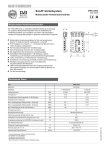
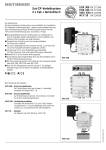
Multischalter-Verteilnetzverstärker
VWS 2551
20510045
VWS 2991
20510021
Multischalter-Verteilnetzverstärker
VWS 2551
VWS 2991
20510045
20510021
Merkmale
Hohe Aussteuerfestigkeit der Verstärkerzüge
Hohe Entkopplung zwischen den Verstärkerzügen
Durch die Verwendung einer GaAs Endstufe ist der
terrestrische Verstärker für BK-Anwendung geeignet
Schrittweise einstellbare Dämpfungssteller (1-dB-Stufung)
für den Sat-und den terrestrischen Bereich (alle Sat-Zweige
werden gleichzeitig eingestellt)
Schrittweise einstellbare Vorentzerrung (2/4/6 dB) im Sat-
Bereich (alle Sat-Zweige werden gleichzeitig eingestellt)
ermöglicht einen optimalen Schräglagenausgleich in der
Kaskade
Die Stromversorgung des VWS erfolgt durch Fernspeisung
aus dem Multischalter EXR 2508/2908 über den Sat-Zweig
horizontal low
Optional ist auch eine Ortsspeisung über den DC Anschluss
mit dem Netzteil NCF 18 möglich (hierbei wird nicht die
Versorgung des LNB übernommen)
Alle Sat-Verstärkerzüge sind mit einer DC-Umgehung
ausgerüstet. Die Versorgungsspannung der Multischalter
EXR 2508/2908 für die LNB wird somit durchgeschleift
Durch Verwendung hocheffizienter DC/DC-Wandler ist der
Stromverbrauch der VWS extrem gering
Für die Innenmontage
VWS 2551
Geeignet für den Einsatz im Kathrein-Sat-ZF-Verteilsystem
4 x Sat-ZF (eine Satellitenposition)
terrestrischen Bereich integriert
VWS 2991
Geeignet für den Einsatz im Kathrein-Sat-ZF-Verteilsystem
8 x Sat-ZF (zwei Satellitenpositionen)
In einem Gehäuse sind 8 x Sat und ein Verstärker für den
terrestrischen Bereich integriert
Für beide Satellitenpositionen kann die Dämpfung und
Vorentzerrung getrennt eingestellt werden
Elektronische Geräte gehören nicht
in den Hausmüll, sondern müssen
- gemäß Richtlinie 2002/96/EG DES
EUROPÄISCHEN
PARLAMENTS
UND DES RATES vom 27. Januar
2003 über Elektro- und Elektronik-Altgeräte fachgerecht entsorgt werden.
Bitte geben Sie dieses Gerät am Ende seiner Verwendung zur Entsorgung an den
dafür vorgesehenen öffentlichen Sammelstellen ab.
936.3445/A/0509/1.4d
In einem Gehäuse sind 4 x Sat und ein Verstärker für den
Technische Daten
Typ
Bestell-Nr.
Eingänge
VWS 2551
VWS 2991
20510045
20510021
1 x terrestrisch
4 x Sat-ZF
1 x terrestrisch
8 x Sat-ZF
MHz
47-862
950-2150
47-862
950-2150
Verstärkung ¹)
dB
16
15
16
15
Einstellbereich Dämpfungssteller (1-dB-Schritte)
dB
0-15
0-15
0-15
0-15
Einstellbereich Entzerrung
dB
-
Max. Ausgangspegel (Störprodukte 3. Ordnung)
dBµV
108 ²
Max. Ausgangspegel (Störprodukte 2. Ordnung)
dBµV
104 4)
Max. Betriebspegel für BK (bis 862 MHz) 5)
dBµV
Entkopplung Stamm
dB
Versorgungsspannung
V
+18
+18
Stromaufnahme
mA
85
120
Max. Fernspeisestrom (je Sat-Zweig)
mA
1000
1000
Zulässige Umgebungstemperatur
°C
-20 bis +55
-20 bis +55
F-Connectoren
F-Connectoren
mm
112 x 148 x 44
112 x 228 x 44
St./kg
1 (10)/0,37
1 (10)/0,57
Frequenzbereich
Anschlüsse
Abmessungen (B x H x T)
Verpackungs-Einheit/Gewicht
2/4/6
-
112 ³
108 ²
2/4/6
)
112 ³)
104 ³)
104 4)
104 ³)
96
-
96
-
-
45
-
45
)
)
¹) Frequenzabhängige Verstärkung (Preemphase) in Abhängigkeit der Schalterstellung für Vorentzerrung
²) 60-dB-KMA nach EN 50083-5
³) 35-dB-IMA nach EN 60728-3
4)
60-dB-IMA nach EN 60728-3
5)
Nach EN 60728-3, 60-dB-CTB/CSO, CENELEC-Raster
936.3445/A/0509/2.4d
Abmessungen in mm
Montage- und Sicherheitshinweise
• Die beschriebenen Geräte dienen ausschließlich der Installation von Satelliten-Empfangsanlagen.
• Jegliche anderweitige Nutzung oder die Nichtbeachtung dieses Anwendungshinweises hat den
Verlust der Gewährleistung bzw. Garantie zur Folge.
• Die Geräte dürfen nur in trockenen Innenräumen montiert werden. Nicht auf oder an leicht
entzündlichen Materialien montieren.
• Die Geräte sind mit einer Potenzial-Ausgleichsleitung (Cu, mindestens 4 mm2) zu versehen.
• Die Sicherheitsbestimmungen der jeweils aktuellen Normen EN 60728-11 und EN 60065 sind
zu beachten.
• Befestigungsmittel: Holzschrauben, max Ø: 4,0 mm
• Verbindungsstecker: HF-Stecker 75 Ω (Serie F) nach EN 61169-24.
Allgemeines zur Installation
Einsetzen des Verstärkers in eine Satelliten-Empfangsanlage
Grundsätzlich kann der Verstärker an jeder Position in der Sat-Empfangsanlage eingebaut werden (siehe dazu auch
Punkt „Anlagenbeispiel“). Dabei ist aber folgendes zu beachten:
- der Pegel am Eingang sollte sich in einem Fenster von ca. 50 bis max. 80 dµV bewegen und
- nachfolgende Multischalter dürfen nicht übersteuert werden.
Einpegeln des Verstärkers
Zur Bestimmung des Pegels verwenden Sie am Besten
ein Antennenmessgerät, z. B. MSK 200. Sie können die
Verstärkung in 1-dB-Schritten zurückregeln (siehe Bild
rechts). Der Dämpfungssteller wirkt jeweils auf alle vier
Verstärkerzüge im Sat-Bereich gleichzeitig.
Zum Ausgleich von Schräglagen der Dämpfung, z. B. bei
großen Kabellängen kann man den Verstärker auf 2-,
4- und 6-dB-Vorentzerrung einstellen. Der terrestrische
Verstärker wird mit einem eigenen Regler eingestellt.
Verbindung der Verstärker mit weiteren Geräten der
Sat-Empfangsanlage
Bei weiter voneinander entfernten Geräten empfiehlt sich die Verwendung von
hochwertigen Koaxialkabeln (mit sehr hohen Schirmungswerten) z. B. LCD 111.
Verwenden Sie nach Möglichkeit hochwertige F-Stecker (siehe Bild rechts) zum
„Crimpen“ oder als Kompressionsstecker (siehe Kathrein-Katalog „Satellitenund terrestrische Empfangs-Antennenanlagen“).
Bei Verwendung von Koaxialkabeln achten Sie besonders auf die
richtige Zuordnung der Ein- bzw. Ausgänge zueinander. Der Ausgang „V low“ des Verstärkers muss mit dem Eingang „V low“ des
Multischalters verbunden werden usw.
936.3445/A/0509/3.4d
Die einfachste und schnellste Verbindung, z. B. zu
einem Multischalter EXR 2558/EXR 2998, erhält man
durch den optional erhältlichen Steckverbinder EMU 250
(siehe Bild rechts) bzw. den EMU 290 für den VWS 2991.
Hier werden die Geräte direkt aneinander gesteckt.
• Bei größerem Durchmesser des KabelInnenleiters als 1,2 mm bzw. Grat können
die Gerätebuchsen zerstört werden.
Unter Beachtung der erforderlichen Pegelverhältnisse können in einer Kaskade max. bis zu drei
Verstärker betrieben werden.
Spannungsversorgung des Verstärkers
Kathrein-Verstärker sind mit einem innovativen Versorgungskonzept ausgestattet. Der Verstärker kann auf zwei
Arten versorgt werden:
1. Mittels Fernspeisung über das Koaxialkabel des Anschlusses „H low“ eines End-Multischalters oder
2. Durch Anschluss eines optional erhältlichen Netzteils NCF 18 an die Buchse „DC“ (hierbei wird nicht die Versorgung des Speisesystems übernommen!)
Potenzialausgleich
Für den Potenzialausgleich verwenden Sie einen Erdungsdraht von mindestens
4 mm Querschnitt. Zur Erdung des Gerätes ist die am Gerät vorhandene Erdungsschraube zu verwenden. Jedes Gerät der Empfangsanlage muss geerdet werden.
UAS 584 oder
UAS 585
Terrestrische
Antenne
(Symbolische Darstellung)
EMU 250
(optional)
EMU 250
(optional)
Internet: www.kathrein.de
KATHREIN-Werke KG • Anton-Kathrein-Straße 1 - 3 • Postfach 10 04 44 • 83004 Rosenheim • Deutschland • Telefon 08031 184-0 • Fax 08031 184-306
936.3445/A/0509/4.4d/ZWT Technische Änderungen vorbehalten.
Anlagenbeispiel (Symbolische Darstellung)
Sat-IF distribution system
Multi-switch distribution network
amplifiers
VWS 2551
20510045
VWS 2991
20510021
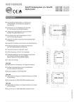
Multi-switch distribution network amplifiers
VWS 2551
VWS 2991
20510045
20510021
Features
High dynamic range of amplifier units
High decoupling between the amplifier units
The terrestrial amplifier is CATV capable due to a GaAs output
stage
Variable attenuator (in 1 dB increments) for the terrestrial
bands and in the SAT-IF range (Sat polarity signals are set
using the one attenuator)
Adjustable pre-equalisation (2/4/6 dB) in the Sat range (all
Sat polarity signals are set using the one attenuator) enables
optimal equalisation of slope in the cascade
The VWS units are powered through remote feeding by
the EXR 2508/2908 multi-switches via Sat signal polarity
horizontal low
Powering can also be carried out through the DC output using
the NCF 18 (does not encompass LNB supply)
All Sat amplifier units are equipped with a DC bypass. This
allows loop-through of the LNB supply voltage of the EXR
2508/2908 multi-switches.
Extremely low power consumption due to high-efficiency
DC/DC converter
For indoor installation
VWS 2551
Suitable for application in the Kathrein Sat-IF distribution
system
4 x Sat-IF (one satellite position)
Five amplifiers (4 x Sat-IF and 1 x terrestrial range) in one
VWS 2991
Suitable for application in the Kathrein Sat-IF distribution
system 8 x Sat-IF (two satellite positions)
Nine amplifiers (8 x Sat-IF and 1 x terrestrial range) in one
housing
Attenuation and pre-equalisation can be set independently for
both satellite positions
Electronic equipment is not household waste, in accordance with directive
2002/96/EC OF THE EUROPEAN
PARLIAMENT AND THE COUNCIL dated
27th January 2003 on used electrical and
electronic equipment,
it must be disposed of properly.
At the end of its service life, take this unit
for disposal to an appropriate official collection point.
936.3445/A/0509/1.4e
housing
Technical Data
Type
Order No.
Inputs
VWS 2551
VWS 2991
20510045
20510021
1 x terrestrial
4 x Sat-IF
1 x terrestrial
8 x Sat-IF
MHz
47-862
950-2150
47-862
950-2150
Gain ¹)
dB
16
15
16
15
Adjustable attenuator setting range (1-dB steps)
dB
0-15
0-15
0-15
0-15
Equalisation setting range
dB
-
Max. output level (interferences 3rd order)
dBµV
108 ²
Max. output level (interferences 2nd order)
dBµV
104 4)
dBµV
Decoupling trunk
dB
Supply voltage
V
+18
+18
Current drain
mA
85
120
Max. remote feed current (each Sat signal
polarity)
mA
1000
1000
Permissible ambient temperature
°C
-20 to +55
-20 to +55
F-type connectors
F-type connectors
mm
112 x 148 x 44
112 x 228 x 44
pc/kg
1 (10)/0.37
1 (10)/0.57
Frequency range
Max. operating level for CATV (up to 862 MHz)
5)
Connections
Dimensions (W x H x D)
Packing unit/Weight
2/4/6
-
2/4/6
112 ³
108 ²
)
112 ³)
104 ³)
104 4)
104 ³)
96
-
96
-
-
45
-
45
)
)
¹) Frequency-dependent gain (pre-emphasis) depending on the pre-equalisation setting
²) 60-dB XMod to EN 50083-5
³) 35-dB IMod to EN 60728-3
4)
60-dB IMod to EN 60728-3
5)
To EN 60728-3, 60-dB CTB/CSO, CENELEC channel plan
936.3445/A/0509/2.4e
Dimensions in mm
Installation and safety instructions
• The units described are intended solely for the installation of satellite receiver systems.
• Any other use, or failure to comply with these instructions, will result in voiding of warranty
cover.
• The units may only be installed in dry indoor areas. Do not mount on or against highly
combustible materials.
• The units should be provided with an equipotential bonding wire (Cu, at least 4 mm2).
• The safety regulations set out in the current EN 60728-11 and EN 60065 standards
must be complied with.
• Suitable securing fastenings: Wood screws, max Ø: 4.5 mm
• Connector: HF plug 75 Ω (series F) to EN 61169-24.
General information on installation
Installation of an amplifier in a satellite reception system
In principle, the amplifier can be built into any position in the Sat reception system (see section “System example”).
The following is to be observed:
- the level on the input should fall within the range between 50 to max. 80 dµV and
- the multi-switches following are not to be overdriven
Levelling the amplifier
In order to define the level, it is recommended to use an
antenna measuring instrument, e.g. MSK 200. You can
adjust the gain in 1-dB increments (see picture on right).
The attenuator affects all Sat-range amplifier units at the
same time.
To equalise attenuation slopes, such as in long cable
lengths, the amplifier’s pre-equalisation can be set to 2,
4 and 6 dB. The terrestrial amplifier is adjusted with its
own attenuator.
Connection of the amplifier to other units of the Sat
reception system
The easiest and quickest way to connect the amplifier to, e.g. a EXR 2558/EXR 2998 multi-switch
is by using the optional connector EMU 250
(see picture on right) or the EMU 290 as is required for
the VWS 2991. This enables the units to be connected
to each other directly.
When using coaxial cables, it is especially important to make sure
that the inputs and outputs are correctly assigned to one another. The amplifier’s “V low” output must be connected to the multiswitch’s “V low” input, etc.
936.3445/A/0509/3.4e
If the units are far apart, it is recommended to use high-quality coaxial cables
(with very high screening values) e.g. LCD 111. If possible, use high-quality Ftype connectors (see picture right) for “crimping” or compression connectors (see
Kathrein catalogue “Satellite and terrestrial antenna products and systems”).
• If the inner cable conductor diameter is
greater than 1.2 mm or in case of burr, the
device sockets may be destroyed.
Max. 2 mm excess
length
Diameter
0.6-1.2 mm
free of burrs
Clamping torque max.
3 Nm
(danger of overwinding)
If the required level ratios are observed, a maximum number of three amplifiers can be operated in
a cascade.
Amplifier voltage supply
Kathrein amplifiers are equipped with an innovative powering concept. The amplifiers can be powered in two ways:
1. Through remote feeding via the coaxial cable of the “H low” connection on a terminal multi-switch
2. Through connection of the optional NCF 18 power supply unit to the “DC” socket (does not include powering of
the feed system!)
Potential equalisation
For potential equalisation use an earthing wire with a cross section of at least
4 mm. The unit is to be earthed using the earthing screw provided on the unit. Each
unit in the reception system must be earthed.
or
UAS 584 oder
Terrestrische
Terrestrial
UAS 585
antenna
Antenne
(Symbolic
representation)
(Symbolische
Darstellung)
EMU 250
(optional)
EMU 250
(optional)
Internet: www.kathrein.de
KATHREIN-Werke KG • Anton-Kathrein-Straße 1 - 3 • P.O. Box 10 04 44 • 83004 Rosenheim • GERMANY • Telephone +49 (0)8031 184-0 • Fax +49 (0)8031 184-306
936.3445/A/0509/4.4e/ZWT Technical data subject to change.
System example (Symbolic representation)
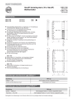
Système de distribution FI Sat
Amplificateur répartiteur commutateur
multiple
VWS 2551
20510045
VWS 2991
20510021
Amplificateur répartiteur commutateur multiple
VWS 2551
VWS 2991
20510045
20510021
Caractéristiques
Grande résistance des sections d’amplification à la
surmodulation
Découplage élevé entre les sections d’amplification
Grâce à l’utilisation d’un étage de sortie GaAs, l’amplificateur
terrestre convient pour l’application câble large bande
Régulateur d’atténuation réglable pas à pas (progression
de 1 dB) pour la gamme Sat et terrestre (toutes les branches
Sat sont réglées en même temps)
Préaccentuation réglable pas à pas (2/4/6 dB) dans la gamme
Sat (toutes les branches Sat sont réglées en même temps)
autorisant une compensation optimale de l’inclinaison dans
la cascade
L’alimentation électrique du VWS se fait par téléalimentation
à partir du commutateur multiple EXR 2508/2908 au travers
de la branche Sat horizontale basse
Une alimentation locale via la prise CC avec le bloc
d’alimentation NCF 18 est également possible en option
(l’alimentation du LNB n’est alors pas assurée)
Toutes les sections d’amplification Sat possèdent un
contournement CC. La tension d’alimentation des
commutateurs multiples EXR 2508/2908 pour les LNB
est ainsi bouclée
Grâce à l’utilisation de transformateurs CC/CC à haute
efficacité, la consommation de courant des VWS est
extrêmement faible
Pour montage en intérieur
Convient pour l’utilisation dans le système de distribution
FI Sat Kathrein 4 x FI Sat (une position satellite)
4 x Sat et un amplificateur pour la gamme terrestre sont
intégrés dans un boîtier
VWS 2991
Convient pour l’utilisation dans le système de distribution
Les appareils électroniques ne sont pas
des déchets domestiques et doivent à ce
titre, conformément au règlement 2002/96/
CEE DU PARLEMENT EUROPEEN ET
DU CONSEIL du 27 janvier 2003 portant
sur les déchets d’équipements électriques
et électroniques, être éliminés comme il se
doit.
FI Sat Kathrein 8 x FI Sat (deux positions satellite)
8 x Sat et un amplificateur pour la gamme terrestre sont
intégrés dans un boîtier
L’atténuation et la préaccentuation peuvent être réglées
séparément pour les deux positions satellite
Veuillez remettre cet appareil, lorsqu’il sera
hors d’usage, à un point de collecte officiel
spécialement prévu à cet effet.
936.3445/A/0509/1.4f
VWS 2551
Caractéristiques techniques
Type
VWS 2551
VWS 2991
20510045
20510021
Référence
Entrées
1 x terrestre
4 x FI Sat
1 x terrestre
8 x FI Sat
MHz
47-862
950-2150
47-862
950-2150
Gain ¹)
dB
16
15
16
15
Plage de réglage du régulateur d’atténuation (par pas de 1 dB)
dB
0-15
0-15
0-15
0-15
Plage de réglage de la correction
dB
-
Niveau de sortie max. (produits parasites du 3ème ordre)
dBµV
108 ²
Niveau de sortie max. (produits parasites du 2ème ordre)
dBµV
104 4)
Niveau de sortie max. pour câble large bande (jusqu’à 862 MHz) 5)
dBµV
Découplage ligne principale
dB
Tension d'alimentation
V
+18
+18
Consommation de courant
mA
85
120
Courant de téléalimentation max. (par branche Sat)
mA
1000
1000
Température ambiante admissible
°C
-20 à +55
-20 à +55
Connecteurs F
Connecteurs F
Plage de fréquences
Raccordements
2/4/6
-
2/4/6
112 ³
108 ²
)
112 ³)
104 ³)
104 4)
104 ³)
96
-
96
-
-
45
-
45
)
)
Dimensions (l x h x p)
mm
112 x 148 x 44
112 x 228 x 44
Unité d’emballage/Poids
u./kg
1 (10)/0,37
1 (10)/0,57
1)
Gain lié à la fréquence (préaccentuation) en fonction de la position du commutateur de préaccentuation
2)
60 dB KMA selon EN 50083-5
3)
35 dB IMA selon EN 60728-3
4)
60 dB IMA selon EN 60728-3
5)
Selon EN 60728-3, 60 dB CTB/CSO, grille CENELEC
936.3445/A/0509/2.4f
Dimensions en mm
Consignes de montage et de sécurité
• Les appareils décrits ici sont exclusivement destinés à l'installation de systèmes de réception
satellite.
• Tout autre usage, de même que le non respect des présentes consignes, entraînera l’annulation
de la garantie.
• Les appareils ne doivent être montés que dans des environnements intérieurs non humides.
Ne pas les monter sur ou contre des matériaux facilement inflammables.
• Ces appareils doivent être pourvus d’une ligne équipotentielle (Cu, 4 mm2 minimum).
• Observer les consignes de sécurité des normes EN 60728-11 et EN 60065.
• Dispositifs de fixation : vis à bois, Ø max. : 4,0 mm
• Connecteurs : connecteurs HF 75 Ω (série F) selon EN 61169-24.
Généralités sur l’installation
Mise en place de l’amplificateur dans une installation de réception satellite
L’amplificateur peut par définition être monté en toute position de l’installation de réception Sat (voir également
« Exemple d’installation »). Observer les indications suivantes :
- le niveau en entrée doit se situer dans une plage d’env. 50 à max. 80 dµV et
- les commutateurs multiples consécutifs ne doivent pas être saturés.
Ajustement de l'amplificateur
Pour déterminer le niveau, utilisez de préférence
un appareil de mesure pour antennes, par ex. le
MSK 200. Le gain peut être réglé par pas de 1 dB (voir
la figure de droite). Le régulateur d’atténuation agit
simultanément sur les quatre sections d’amplification
de la gamme Sat.
Pour compenser les inclinaisons de l’atténuation, par
ex. avec des câbles de grande longueur, l’amplificateur
peut être réglé sur une préaccentuation de 2,
4 et 6 dB. L’amplificateur terrestre est réglé avec son
propre régulateur.
Raccordement des amplificateurs aux
appareils de l’installation de réception Sat
autres
Si les appareils sont éloignés entre-eux, il est conseillé d’utiliser des câbles
coaxiaux de qualité (à facteur de blindage très élevé), par ex. du LCD 111.
Utilisez si-possible des connecteurs F de qualité (voir la figure de droite) à sertir
ou à serrage (voir le catalogue Kathrein « Installations de réception satellite et
terrestre »).
En cas d’utilisation de câbles coaxiaux, observez bien la
correspondance entre les entrées et sorties. La sortie « V low » de
l’amplificateur doit être reliée à l’entrée « V low » du commutateur
multiple, etc.
936.3445/A/0509/3.4f
La liaison la plus simple et la plus rapide avec par ex.
un commutateur multiple EXR 2558/EXR 2998 est
obtenue à l’aide du connecteur EMU 250 disponible
en option (voir la figure de droite) ou EMU 290 pour
le VWS 2991. Les appareils sont alors enfichés
directement.
• Si le diamètre du conducteur interne est
supérieur à 1,2 mm ou en présence d’ébarbures,
les connecteurs femelles de l’appareil sont
susceptibles d’être endommagés.
Dépassement max.
2 mm
Diamètre 0,61,2 mm sans
bavures
Couple de serrage
max. 3 Nm
(risque de serrage
excessif)
Compte tenu des niveaux requis, trois amplificateurs peuvent être utilisés au maximum dans une
cascade.
Alimentation électrique de l'amplificateur
Les amplificateurs Kathrein bénéficient d’un concept d’alimentation novateur. L’amplificateur peut être alimenté de
deux manières :
1. Par téléalimentation par le câble coaxial du branchement « H low » d’un commutateur multiple final ou
2. Par le raccordement d’un bloc d’alimentation NCF 18 disponible en option à la prise « CC » (le système
d’alimentation LNB n’est pas alimenté !)
Liaison équipotentielle
Utilisez pour la liaison équipotentielle du fil de terre d’une section d’au moins
4 mm. Mettre l’appareil à la terre à l’aide de la vis de terre prévue à cet effet.
Chaque appareil de l’installation de réception doit être mis à la terre.
UAS
584 oder
ou
UAS 584
Antenne
terrestre
Terrestrische
UAS 585
UAS
585
(représentation
symbolique)
Antenne
(Symbolische Darstellung)
EMU
250
EMU 250
(en
option)
(optional)
EMU 250
EMU
250
(optional)
(en
option)
Internet : www.kathrein.de
KATHREIN-Werke KG • Anton-Kathrein-Straße 1 - 3 • Boîte postale 100 444 • 83004 Rosenheim • ALLEMAGNE • Téléphone +49 8031 184-0 • Fax +49 8031 184-306
936.3445/A/0509/4.4f/ZWT Sous réserve de modifications !
Exemple d'installation (représentation symbolique)