1
1
Instruction Manual for SUPERLINE series battery back-ups
TABLE OF CONTENTS
TABLE OF CONTENTS ........................................................................................................................................2
INTRODUCTION ...................................................................................................................................................3
GENERAL INFORMATION..................................................................................................................................3
PURPOSE OF THE DEVICE ........................................................................................................................... 3
GENERAL FEATURES.................................................................................................................................... 3
ELEMENTS OF THE BATTERY BACK-UP........................................................................................................5
USER INTERFACE .......................................................................................................................................... 6
SCREENS.......................................................................................................................................................... 8
Main menu...............................................................................................................................................................8
The POMIARY (MEASUREMENTS) submenu ....................................................................................................9
The KONTROLA (CONTROL) submenu ............................................................................................................11
The KONFIGURACJA (CONFIGURATION) submenu......................................................................................13
The ALARMY (ALERTS) submenu.....................................................................................................................15
The STATYSTYKA (STATISTICS) submenu.....................................................................................................17
The USTAWIENIA PANELU (PANEL SETTINGS) submenu...........................................................................18
The IDENTYFIKACJA (IDENTIFICATION) submenu ......................................................................................19
SAFETY AND HEALTH INSTRUCTIONS........................................................................................................20
HANDLING .................................................................................................................................................... 20
ELECTRIC SAFETY ...................................................................................................................................... 20
INSTALLATION ..................................................................................................................................................21
UNPACKING.................................................................................................................................................. 21
INSTALLATION OF THE BATTERY BACK-UP........................................................................................ 22
THE BATTERY MODULE ............................................................................................................................ 23
Connecting the modules ........................................................................................................................................23
Disconnecting the modules....................................................................................................................................24
CONNECTING THE BATTERY BACK-UP ................................................................................................. 25
Connection terminals .............................................................................................................................................25
Electric system.......................................................................................................................................................26
STARTING THE BATTERY BACK-UP ....................................................................................................... 27
POWERING OFF AND DISCONNECTING THE BATTERY BACK-UP................................................... 27
OPERATING MODES OF THE BATTERY BACK-UP ............................................................................... 28
OTHER FUNCTIONAL ELEMENTS............................................................................................................ 30
Safeguards .............................................................................................................................................................30
EPO.................................................................................................................................................................. 32
Manual BYPASS ............................................................................................................................................. 32
COMMUNICATION BETWEEN THE UPS AND A COMPUTER.............................................................. 33
COMMUNICATION VIA RS232 OR USB .........................................................................................................33
EVER SNMP/HTTP NETWORK CONTROL CARD .........................................................................................33
INSTALLATION AND CONFIGURATION OF THE POWERSOFT PERSONAL SOFTWARE.............. 35
Installation on computers with Windows ..............................................................................................................35
Installation on computers with Linux/Unix ...........................................................................................................35
Software updates....................................................................................................................................................36
ADDITIONAL REMARKS ..................................................................................................................................37
BATTERY BACK-UP AND POWER GENERATORS................................................................................. 38
STORAGE, MAINTENANCE AND TRANSPORT ...................................................................................... 38
DISPOSAL ...................................................................................................................................................... 38
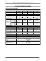
TECHNICAL PARAMETERS .............................................................................................................................39
INSTALLATION GUIDELINES.................................................................................................................... 39
TECHNICAL DATA....................................................................................................................................... 40
INFORMATION REGARDING REGULATIONS AND WARRANTY.............................................................41
DECLARATION OF CONFORMITY............................................................................................................ 41
WARRANTY ....................................................................................................................................................... 41
2010/01/12
www.ever.eu
2
Instruction Manual for SUPERLINE series battery back-ups
INTRODUCTION
Thank you for purchasing the EVER SUPERLINE battery back-up (UPS). It is the
latest series of state-of-the-art power supply devices designed to work with servers,
computer networks, and data processing systems.
The SUPERLINE series EVER UPS was designed so as to meet all your
expectations for protection against power loss.
This instruction manual contains information pertaining to the control of the device,
as well as rules for safe operation. Please familiarise yourself with the contents of
this manual prior to beginning your work with the EVER SUPERLINE battery back-up
in order to ensure proper usage. The battery back-up was manufactured in Poland
and its structure conforms to requirements of the CE symbol.
GENERAL INFORMATION
PURPOSE OF THE DEVICE
SUPERLINE series battery back-ups are ONLINE (VFI)-class devices designed for
work with equipment powered by monophase ~230 mains.
WARNING! SUPERLINE battery back-ups were not designed to
work with life and/or health support medical equipment.
GENERAL FEATURES
SUPERLINE battery back-ups consist of the following functional units:
•
Rectifier assembly with PFC system (power factor correction),
•
Accumulator charger,
•
Accumulator assembly,
•
Inverter utilising the high-frequency IGBT technology,
•
Automatic bypass system (static BYPASS),
•
Manual (maintenance) bypass system (manual UPS/BYPASS switch),
•
Microchip control system with measuring systems.
2010/01/13
www.ever.eu
3
Instruction Manual for SUPERLINE series battery back-ups
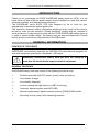
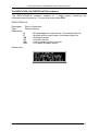
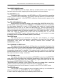
Figure 1: Simplified block diagram of the battery back-up
The input rectifier converts the alternating mains current to a direct current. The
power factor correction system used in the rectifier enables significant elimination of
noise transferred to the power system. The direct current bus is the main source of
power of the inverter which produces sine alternating current that powers the
receivers. An internal charger is responsible for charging the accumulator; it has
a very low alternating charging current component, which significantly extends
accumulator life. The microchip control system ensures precise and reliable
operating of the whole power supply system.
The automatic bypass system increases the safety of the whole system. If the
tolerance limits for the parameters of the inverter are exceeded, the mains current is
provided to the load directly. This way the automatic bypass system constitutes an
additional, passive safeguard of connected load. The additional function of manual
engaging of the bypass enables complete powering of load from the mains. This way
it is possible to supply power to the load from the mains without any involvement of
the battery back-up’s internal functional units.
2010/01/13
www.ever.eu
4
Instruction Manual for SUPERLINE series battery back-ups
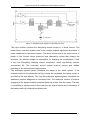
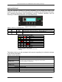
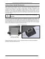
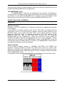
ELEMENTS OF THE BATTERY BACK-UP
1) Cover of the BYPASS switch
2) Fans
3) Cover of the upgrade card slot
4) USB communication port
5) RS232 communication port
6) EPO connector
7) Internal accumulator fuse
8) Cover of connection terminals
9) Input AC circuit breakers
10) Mechanical cable clamps
11) Maintenance BYPASS/UPS
switch
12) Connection terminals
13) External battery module fuse
14) Earthing point
15) Installation grips
Figure 2: Rear panel
2010/01/13
www.ever.eu
5
Instruction Manual for SUPERLINE series battery back-ups
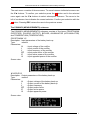
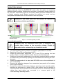
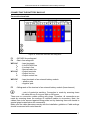
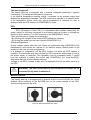
USER INTERFACE
The user interface consists of a 4-button keyboard, a LCD display and three LEDs
located on the top cover of the battery back-up. It enables the monitoring of the backup’s operating parameters and modification thereof. Interface operation and the
meaning of individual parameters are described below.
Figure 3: User interface
Table 1: Meaning of signalling LEDs
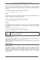
Graphic symbol
Designation
Description
LED 1
Signalling LED indicating the back-up’s operation mode: NORMAL/BATTERY
LED 2
Signalling LED indicating the ON status of the BYPASS line
LED 3
Signalling LED indicating the EMERGENCY mode
Table 2: Optical signalling (LEDs)
LED 1
LED 2 LED 3
F
F
F
F
E
F
F
*
*
*
Operation mode
UNKNOWN
NORMAL
ECO
BYPASS
BATTERY
STANDBY
SLEEP
EMERGENCY
INIT
STOP
HYBRID
E – if EPO has been triggered the signalling is off, in all other cases the
signalling of emergency mode is enabled.
F – mode dependent on configuration (no colour or red)
* – blinking
The battery back-up is also equipped with acoustic signalling for individual statuses
of the device (see table).
Table 3: Acoustic signalling
Action
Acoustic signalling
NORMAL mode
None
HYBRID mode
Intermittent signal, rate depending on the charge level of accumulators
(quick rate indicates low charge level)
BATTERY mode
Forced switch into
STANDBY mode
EMERGENCY mode
Intermittent signal – two signals in quick succession followed by a pause
Depending on the event
Overloads Continuous signal
Shorting Quick intermittent signal with a 50-50 distribution
Overheating Slow intermittent signal with a 50-50 distribution
EPO triggered Intermittent signal with a signal/silence distribution of 1s / 5s
2010/01/13
www.ever.eu
6
Instruction Manual for SUPERLINE series battery back-ups
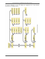
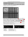
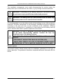
Figure 4: Screen structure
All screens displayed on the LCD display are organised into a tree structure
presented on the diagram below.
2010/01/13
www.ever.eu
7
Instruction Manual for SUPERLINE series battery back-ups
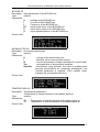
SCREENS
SCREENSAVER
Description: Information screen displayed as a screensaver when no button is
pressed for 5 minutes. Simultaneously the LCD panel backlight is
switched off.
Type:
readout
Parameters:
Qak
–charge level of accumulators
Uak
–voltage of the accumulator unit
Owy
–back-up load level
Tau
–estimated time of autonomous operation of the back-up
TrybPracy –operating mode of the battery back-up
i:, a:
–additional information as in the table below
Informative
Alerts
Abbr.
Meaning
Abbr.
L
Charging
ZW
Shorting
PC
Overload
PC
Overload
PG
Overheat
PG
Overheat
AU
Accumulator damage
S
Waiting after STANDBY
90 seconds of battery
operation remaining
Maintenance
B
BYPASS
O
AN
Meaning
EPO
EPO
BW
Internal error
e.g. a:PC
e.g. i:S+B
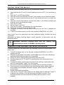
Screen view:
Main menu
2010/01/13
www.ever.eu
8
Instruction Manual for SUPERLINE series battery back-ups
The main menu consists of three screens. To move between individual screens use
the ▼▲ buttons. To confirm your selection press the
button and in the selected
menu again use the ▼▲ buttons to select subsequent submenu. The arrow to the
left of a submenu item indicates the current selection. Confirm your selection with the
button. Pressing ESC returns the user to the previous screen.
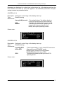
The POMIARY (MEASUREMENTS) submenu
The POMIARY (MEASUREMENTS) submenu consists of five items: PROSTOWNIK
(RECTIFIER), WYJSCIE (OUTPUT), BYPASS, AKUMULATOR (ACCUMULATOR)
and TEMPERATURA (TEMPERATURE).
PROSTOWNIK 1/5
Description: Input parameters of the battery back-up
Type:
readout
Parameters:
U
–Input voltage of the rectifier
I
–Input current of the rectifier
f
–Input frequency of the rectifier
PF
–Input power factor of the rectifier
P
–Input active power of the rectifier
S
–Input apparent power of the rectifier
Screen view:
WYJŚCIE 2/5
Description: Output parameters of the battery back-up
Type:
readout
Parameters:
U
–Output voltage of the battery back-up
I
–Output current of the battery back-up
f
–Output frequency
PF
–Output power factor
P
–Output active power
S
–Output apparent power
Screen view:
2010/01/13
www.ever.eu
9
Instruction Manual for SUPERLINE series battery back-ups
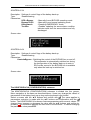
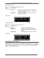
BYPASS 3/5
Description: Input parameters of the BYPASS line
Type:
readout
Parameters:
U
–Voltage of the BYPASS line
I
–Current of the BYPASS line
f
–Frequency of the BYPASS line
PF
–Input power factor of the BYPASS line
P
–Input active power of the BYPASS line
S
–Input apparent power on the BYPASS line
Screen view:
AKUMULATOR 4/5
Description: Accumulator parameters
Type:
readout
Parameters:
U
–voltage of the accumulator unit
I
–Absolute value of accumulator current
Q
–Level of accumulator charge (calculated for current load)
Tau
–estimated time of autonomous operation
StanAku.
–Accumulator wear indicator; the value is updated each
time the accumulators are completely discharged if the
TestAku parameter is enabled; 100% (default value)
indicates full accumulator efficiency.
Screen view:
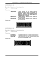
TEMPERATURA 5/5
Description: Temperature parameters
Temperature of internal elements of the battery back-up.
Type:
readout
Parameters:
T0
–Temperature of internal elements of the battery back-up
T1
–Temperature of internal elements of the battery back-up
Screen view:
2010/01/13
www.ever.eu
10
Instruction Manual for SUPERLINE series battery back-ups
The KONTROLA (CONTROL) submenu
The KONTROLA (CONTROL) submenu is divided into four groups. Menu navigation
is the same as described above. Users may change the battery back-up’s
configuration but it must be noted that changes to individual items are possible only
once certain conditions are met. See the table above.
Table 4: Table of changes to configuration flags
{0><}100{>EMERGENCY<0}
BYPASS
STANDBY
SLEEP
STOP
ECO
BATTERY
HYBRID
NORMALN
INIT
Control flag
AwaryjneWylaczenie (emergency
stop)
UNKNOWN
Operation mode
X
●
●
●
●
●
●
●
●
●
UPS
X
X
○
○
○
○
●
■
○
○
X
X
Buzzer
X
□
□
□
□
□
□
□
□
□
□
Czas.Wyl.EPO (EPO switch-off time)
X
□
□
□
□
□
□
□
□
□
□
UPS->STB/STB->UPS
X
X
X
X
●
X
X
X
X
X
X
ECO
X
X
X
X
X
X
□
□
X
X
X
UPS->Bypass/Bypass-UPS
X
X
●
●
●
●
X
X
X
○
X
KasujAwarie (reset malfunction)
X
X
X
X
X
X
X
X
X
X
●
TestAku (accumulator test)
X
□
□
□
□
□
□
□
□
□
□
KontrolaBypass (bypass control)
X
□
X
X
X
X
□
□
X
X
X
Select a screen with the ▲▼ buttons and confirm with
. The same applies to
parameters: selection is made with the ▲▼ buttons and confirmation with the
button. The KONTROLA submenu features two types of parameters. Some of the
parameters require additional confirmation of changes (by pressing
) or enable
cancelling the changes (by pressing ESC), e.g. AwaryjneWylaczenie. Changing
other parameters consists in setting the desired flag by selecting Wl (On) or Wyl (Off)
. Confirmation
with the ▲▼ buttons and confirming the selection by pressing
displays the next screen in the tree structure.
Confirming a parameter setting saves it in the battery back-up’s memory. The saving
process is indicated by the following messages:
-- Trwa zapis --- Zapis OK --- Blad zapisu --- Zla wartość --
2010/01/13
- saving in progress
- saving completed successfully
- saving failed, try again
- value outside tolerance range
www.ever.eu
11
Instruction Manual for SUPERLINE series battery back-ups
Messages are displayed for a short time in the bottom line of the display and then the
menu returns one level up. This rule applies to all modifiable parameters. Sample
saving screens are presented below.
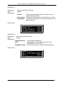
KONTROLA 1/4
Description: Settings of control flags of the battery back-up.
Type:
Readout/saving
Parameters:
AwaryjneWylaczenie –Forced switching of the battery back-up
to the EPO mode from the user interface
UPS
–Switching the battery back-up on and off
Buzzer
–Switching on and off the signalling of the
charge level of accumulators in the
battery and hybrid operating modes
Screen view:
KONTROLA 2/4
Description: Settings of control flags of the battery back-up.
Type:
Readout/saving
Parameters:
Czas.Wyl.EPO
–Timed deactivation (1 min) of the EPO connector.
UPS->STB
–Manually forced STANDBY mode;
Switching after certain time has elapsed
(KONFIGURACJA 2/4; Opoz.STB)
ECO
–Switching the battery back-up to the ECO
operating mode.
Screen view:
2010/01/13
www.ever.eu
12
Instruction Manual for SUPERLINE series battery back-ups
KONTROLA 3/4
Description: Settings of control flags of the battery back-up.
Type:
Readout/saving
Parameters:
UPS->Bypass
–Manually forced BYPASS operating mode.
Bypass->UPS
–Manually forced normal operating mode
KasujAwarie
–Resetting EMERGENCY mode
TestAku
–Enables updating the accumulator condition
indicator each time the accumulators are fully
discharged.
Screen view:
KONTROLA 4/4
Description: Settings of control flags of the battery back-up.
Type:
Readout/saving
Parameters:
KontrolaBypass –Switching the control of the BYPASS line on and off;
This parameter is automatically switched on during
the configuration of the battery back-up to work in
ECO mode; control of the BYPASS line is available
only when the back-up is switched on.
Screen view:
The KONFIGURACJA (CONFIGURATION) submenu
The KONFIGURACJA (CONFIGURATION) submenu is divided into four groups.
Menu navigation is the same as described above. Users may change the values of
parameters of the battery back-up as long as the keyboard is not locked.
Select a screen with the ▲▼ buttons and confirm with . The same applies to
parameters: selection is made with the ▲▼ buttons and confirmation with the
button. The KONFIGURACJA submenu features parameters with numeric values. To
change them, increase or decrease the value with the ▲▼ buttons and confirm by
pressing . Confirmation displays the next level in the structure. To cancel changing
the parameter value press ESC.
2010/01/13
www.ever.eu
13
Instruction Manual for SUPERLINE series battery back-ups
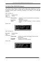
KONFIGURACJA 1/4
Description: Parameters of the battery back-up
Type:
Readout/saving
Parameters:
UWyjsciowe
UGornyProg
UDolnyProg
–Output voltage of the battery back-up;
changes of output voltage by modifying the
parameter while in inverter operating modes
take place only when the battery back-up’s
operating mode is changed.
–Upper threshold value of correct voltage for
the BYPASS line
–Lower threshold value of correct voltage for
the BYPASS line
Screen view:
KONFIGURACJA 2/4
Description: Parameters of the battery back-up
Type:
Readout/saving
Parameters:
fDolnyProg
fGornyProg
Opoz.STB
–Lower threshold value of correct mains frequency
–Upper threshold value of correct mains frequency
–Delay time when the user forces the battery backup to switch to STANDBY mode.
Screen view:
2010/01/13
www.ever.eu
14
Instruction Manual for SUPERLINE series battery back-ups
KONFIGURACJA 3/4
Description: Parameters of the battery back-up
Type:
Readout/saving
Parameters:
Poj. z STB.
–Minimum charge level the accumulators must
reach for the battery back-up to start after
a complete discharge.
ProgKas.Prz.
–Load level at which the battery back-up stops
signalling an overload.
Screen view:
KONFIGURACJA 4/4
Description: Parameters of the battery back-up
Type:
Readout/saving
Parameters:
Poj.Aku.
–Capacity of used accumulators
LiczbaSekcji
–Number of accumulator sections (sum
of internal and external accumulator
sections)
Pr.Ladowania
–Total charging current of accumulators
Screen view:
The ALARMY (ALERTS) submenu
The ALARMY submenu consists of two screens. Menu navigation is the same as
described above. Select a screen with the ▲▼ buttons and confirm with . Alert
screens inform the user about the type of alert that caused the battery back-up to
switch to the EMERGENCY mode.
2010/01/13
www.ever.eu
15
Instruction Manual for SUPERLINE series battery back-ups
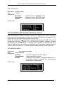
ALARMY 1/2
Description:
Type:
Parameters:
Alerts of the battery back-up.
readout
Zwarcie
–Shorting at the battery back-up’s output when in
inverter operating mode.
PrzeciąŜenie –Excessive load connected to the back-up’s output.
Przegrzanie –Excessive temperature of internal elements of the
battery back-up.
Screen view:
ALARMY 2/2
Description:
Type:
Parameters:
Alerts of the battery back-up.
readout
AkuUszkodzony
EPO
BladWewnetrzny
–Accumulator malfunction
–Forced switch of the battery back-up to the
EMERGENCY mode (EPO)
–Internal device error, contact technical support.
Screen view:
2010/01/13
www.ever.eu
16
Instruction Manual for SUPERLINE series battery back-ups
The STATYSTYKA (STATISTICS) submenu
The STATYSTYKA submenu consists of three screens. Menu navigation is the same
as described above. Select a screen with the ▲▼ buttons and confirm with .
Individual screens contain information pertaining to the history of the back-up’s
operation.
STATYSTYKA 1/3
Description:
Type:
Parameters:
Statistical data.
readout
Niepraw.Siec
–Number of events connected with incorrect mains
parameters.
–Number of overloads.
–Number of output shortings in inverter operating
modes.
Przeciazen
Zwarc
Screen view:
STATYSTYKA 2/3
Description:
Type:
Parameters:
Statistical data.
readout
Rozladowan
Przegrzan
PrzeciąŜ
–Number of complete discharges of the back-up's
accumulators.
–Number of overheats.
–Operation time under overload.
Screen view:
2010/01/13
www.ever.eu
17
Instruction Manual for SUPERLINE series battery back-ups
STATYSTYKA 3/3
Description: Statistical data.
Type:
readout
Parameters:
Normalna
–Operation time in NORMAL mode.
Rezerwowa
–Operation time in BATTERY mode.
Bypass
–Operation time in BYPASS mode.
Screen view:
The USTAWIENIA PANELU (PANEL SETTINGS) submenu
The USTAWIENIA PANELU submenu consists of a single screen. Menu navigation
is the same as described above. Users may change the values of parameters of the
battery back-up as long as the keyboard is not locked.
Select the screen with , parameter selection is done with the ▲▼ buttons and
confirmation with the
button. The USTAWIENIA PANELU submenu features
parameters with numeric values. To change them, increase or decrease the value
with the ▲▼ buttons and confirm by pressing . Confirmation displays the next
screen in the tree structure. To cancel changes of the parameter value press ESC.
USTAWIENIA PANELU
Description:
User interface settings.
Type:
Readout/saving
Parameters:
Kontrast
–Level of contrast of the LCD display.
Podswietlanie
–Display backlight intensity.
Blok.Kl.
–Keyboard lock indicator; changes available only in
the control software; keyboard lock prevents any
modifications of parameters.
Screen view:
2010/01/13
www.ever.eu
18
Instruction Manual for SUPERLINE series battery back-ups
The IDENTYFIKACJA (IDENTIFICATION) submenu
The IDENTYFIKACJA submenu consists of a single screen containing the
information about the device. To leave this screen press ESC.
IDENTYFIKACJA
Description:
Type:
Parameters:
Device information.
Readout/saving
S
P
VH
VF
VP
VFP
–Nominal apparent output power of the battery back-up.
–Nominal active output power of the battery back-up.
–Hardware version
–Firmware version
–Communication protocol version
–LCD panel firmware version
Screen view:
2010/01/13
www.ever.eu
19
Instruction Manual for SUPERLINE series battery back-ups
SAFETY AND HEALTH INSTRUCTIONS
HANDLING
•
•
•
exercise utmost caution when handling the device;
due to the weight of the device, it is equipped with rubber castors;
storage and operation of the device should take place in conditions
conforming to its specification.
ELECTRIC SAFETY
•
•
•
Never work alone in conditions that may be hazardous to health and/or life;
even a momentary shorting of a strong current may lead to severe burns;
before connecting the device to the mains inspect the condition of power
leads, plugs and sockets, as well as the condition of the device itself;
•
in order to avoid the risk of electric shock when connecting and disconnecting
communication cables and touching two surfaces with differing electric
potential, if possible use only one hand;
•
the device must be plugged in to a three–lead installation (1P+N+PE) – failure
to follow this recommendation may result in electric shock;
Users are forbidden to carry out any repairs, as they may lead to injury or death. Any
repairs and replacement of batteries should be conducted only by a qualified
representative of the technical support.
WARNING! The battery back-up is disconnected from the mains only
when the power cord is removed from its socket.
WARNING! Since the device is equipped with internal power source
(batteries) the output may provide hazardous voltage even though
the device itself is not connected to the mains.
WARNING! SUPERLINE battery back-ups were not designed to work
with life support medical equipment.
2010/01/13
www.ever.eu
20
Instruction Manual for SUPERLINE series battery back-ups
INSTALLATION
WARNING!
Before
installing
the
battery back-up
you
must
obligatorily familiarise yourself with the safety and health measures
provided in the previous chapter.
UNPACKING
Please inspect the battery back-up upon receipt. Although the product is delivered in
a packaging it could have sustained damage from inappropriate conditions during
transport. Should you find any damages, please inform the carrier or vendor
immediately.
WARNING! The device may be delivered with its accumulators
connected.
The device is placed on a wooden pallet that facilitates its transportation with
a forklift.
In order to unpack the device you need to cut the belts fastening it to the pallet. Next,
remove the cardboard packaging by sliding it upwards. Remove protective elements.
WARNING! While on the pallet, the device stands on polyethylene
foam which impacts its stability. Upsetting the device may create
hazard to health or life.
If the device is delivered with accumulators, please bear in mind its significant weight
– see the technical parameters table. To remove the device from the pallet use belts
and a lift.
If the device is delivered without accumulators installed, it should be removed from
the pallet by at least 3 persons.
Verify the contents of the packaging. The packaging should contain:
•
•
•
•
•
•
•
2010/01/13
the battery back-up,
instruction manual and PowerSoft Personal installation CD-ROM,
RS232 communication cable to connect the back-up to a computer,
USB communication cable to connect the back-up to a computer,
A set of 10x38 fuses (2 pcs)
warranty card
installation grips (2 pcs).
www.ever.eu
21
Instruction Manual for SUPERLINE series battery back-ups
INSTALLATION OF THE BATTERY BACK-UP
When choosing the installation spot you must take the device's weight into account.
The back-up should only be used in rooms where dustiness, temperature and
moisture levels conform to the device's specification. In order to ensure correct
operation of the back-up, appropriate cooling conditions for the device must be
provided. For this reason the ventilation openings on the back-up's case must be
uncovered and the distance between the back-up and other objects should not be
lower than 30 cm.
WARNING! The device must not be installed close to flammable
materials!
Before positioning the battery back-up two additional installation grips need to be
mounted in order to ensure stability of the device and enable fixing it to the floor. To
this end please remove the 4 M8 screws located in the central section of the device’s
bottom side. Gently tilt the battery back-up and place the grips. Next, screw the grips
down to the UPS with the screws previously removed.
Figure 10: Installation grips
Detailed information may be found in a separate document containing installation
guidelines, delivered with the device.
2010/01/13
www.ever.eu
22
Instruction Manual for SUPERLINE series battery back-ups
THE BATTERY MODULE
Battery back-ups from the SUPERLINE series offer the option of connecting
additional battery modules. Modules are connected to connection clamps located on
the rear panel of the battery back-up. Connecting battery modules extends the time
of battery operation mode. Battery modules are installed in a series and are
safeguarded with additional cut-offs located on their rear panels.
WARNING! If the fuses burn out, they should be replaced in
accordance with the specification.
Figure 11: Connecting battery modules
Connecting the modules
WARNING! With the safeguards active there is hazardous, and
possibly lethal, voltage on the connection clamps. Disable all
safeguards before commencing any installation works!
1.
2.
3.
4.
5.
6.
7.
Turn off the battery back-up via the user interface (KONTROLA 1/4; UPS).
Switch the F3 and F4 circuit breakers to OFF.
Disable all accumulator safeguards (F1, F2 and F5) by opening the fuse
holders. There is no fixed order to do this. Remove the fuse-elements.
Disable all accumulator safeguards for the already connected battery modules
and those being connected by opening the fuse holders and removing the fuseelements.
Disable the safeguards of the basic and BYPASS lines on the switchboard of
the room/building.
Remove the protective stoppers from connectors (rear panels of the battery
back-up and modules).
Connect the module to the battery back-up, ensuring correct terminal polarity.
Modules are connected in a series: UPS to first module, then first module to
second module, second module to third module and so on. Protective earthing
cables from each device are connected to a common point in the
room’s/building’s switching station.
2010/01/13
www.ever.eu
23
Instruction Manual for SUPERLINE series battery back-ups
8.
9.
10.
11.
12.
13.
14.
15.
16.
17.
After verifying the correctness of connections secure the terminals by replacing
the stoppers. Secure the cables against accidental pulling out by fastening them
with bands to special grips located below the terminals.
Enable the safeguards in the room’s/building’s switching station.
Replace the fuse-elements in the respective holders.
Close all fuse holders of all connected battery modules.
Close the F1 holder on the battery back-up.
Wait at least 10 seconds.
Close the F2 holder on the battery back–up – accumulators are now
connected.
Switch the F3 and F4 circuit breakers to ON.
Set up the accumulator parameters of the battery back-up (KONFIGURACJA
4/4).
Launch the battery back-up via the user interface (KONTROLA 1/4; UPS).
The displayed data associated with the number of connected accumulators will be
automatically updated once the accumulators are topped up. Until that time the
indications may differ from the actual state.
Disconnecting the modules
1.
2.
3.
4.
5.
6.
7.
8.
9.
10.
11.
12.
13.
14.
15.
Shut down the battery back-up via the user interface (KONTROLA 1/4; UPS).
Switch the F3 and F4 circuit breakers on the battery back-up to OFF.
Disable the safeguards of the basic and BYPASS lines in the room’s/building’s
switching station.
Disable the F1, F2 and F5 safeguards on the battery back-up and the F1 and
F2 safeguards on all battery modules by opening the fuse holders and removing
the fuse-elements.
Remove the connector stoppers.
Disconnect the modules. The connecting cables must be completely
disconnected.
Secure the connectors by replacing the protective stoppers.
Enable the safeguards in the room’s/building’s switching station.
Replace the fuse-elements in the respective holders.
Close the fuse holders of all connected battery modules (if any).
Close the F1 holder on the battery back-up.
Wait at least 10 seconds.
Close the F2 holder on the battery back–up – accumulators are now
connected.
Switch the F3 and F4 circuit breakers to ON.
Set up the accumulator parameters of the battery back-up (KONFIGURACJA
4/4).
WARNING! Never leave leads unconnected! The current flowing in
them may be hazardous to health and possibly lethal!
2010/01/13
www.ever.eu
24
Instruction Manual for SUPERLINE series battery back-ups
CONNECTING THE BATTERY BACK-UP
Connection terminals
Figure 12: Connection terminals with safeguards
F3
F4
–BYPASS line safeguard
–Basic line safeguard
WEJ AC
LB
L
N
WYJ AC
L
N
–Input terminals
–Live BYPASS line
–Live basic line
–Neutral basic line
–Output terminals
–Output live line
–Output neutral line
WEJ DC
+
-
–Input terminals of an external battery module
– positive pole
–negative pole
F5
–Safeguards of the terminal of an external battery module (fuse-element)
– point of protective earthing. Connection is made by screwing down
the cable with an O-ring end with an M6 screw.
There are no connection cables ending with plugs. Therefore, all connections are
made by screwing down the endings of individual cables to connectors. Next, the
cables have to be secured against being pulled out by fastening them with bands to
special grips located below the connectors.
Make sure the cable diameters comply with the installation guidelines. Cable endings
should be secured with metal sleeves.
2010/01/13
www.ever.eu
25
Instruction Manual for SUPERLINE series battery back-ups
The installation arrangement must enable disconnecting the section where the
battery back-up is connected from the mains, e.g. by turning overcurrent switches.
WARNING! Connecting of the battery back-up to the mains should
be performed only by qualified and authorised personnel.
WARNING! The battery back-up is disconnected from the mains only
when the power cord is removed from its socket.
It is recommended to use the safety circuits of the building as one of the protection
measures. Protection parameters of the buildings' installations should be adjusted
according to the type and size of load connected to the installation. Differing
characteristics of protections of installations in the building and the battery back-up
may in extreme cases lead to quicker responses of the former.
WARNING! The user is obligated to place the following information
on all mains disconnecting switches installed far from the
installation spot of the battery back-up:
“DO THE FOLLOWING BEFORE STARTING WORK ON THIS
CIRCUIT:
- DISCONNECT THE BATTERY BACK-UP SYSTEM (UPS)
- MAKE SURE THERE IS NO RISK OF REVERSE POWER SUPPLY
BETWEEN ANY OF THE CLAMPS (BY ENABLING THE PE CLAMP)”
Electric system
The electric system should comply with the installation guidelines for this type of
battery back-ups. The guidelines constitute a separate document delivered with the
device.
2010/01/13
www.ever.eu
26
Instruction Manual for SUPERLINE series battery back-ups
STARTING THE BATTERY BACK-UP
A correctly connected battery back-up may be started as follows:
1)
Verify whether the F3 and F4 circuit breakers are set to OFF; if not, set them to
OFF.
2) Open the F1 and F2 fuse holders.
3) Insert the correct fuse-element into the F1 fuse holder (do not close the holder).
4) Insert the correct fuse-element into the F5 fuse holder and close it to close the
circuit.
5) Insert the correct fuse element into the fuse holder on the battery module and
close the circuit by closing the holder.
6) Close the F1 holder.
7) Wait at least 10 seconds.
8) Close the F2 holder – accumulators are now connected.
9) Switch the F3 and F4 circuit breakers to ON.
10) Configure the battery back-up (when starting for the first time, if changes are
required).
11) Turn on the battery back-up via the user interface (KONTROLA 1/4; UPS).
Items 4 and 5 are to be performed only when additional battery modules are being
connected.
Afterwards the battery back-up begins normal operation in accordance with the
description below.
WARNING! Back-up's batteries reach their full capacity after
approximately a month of NORMAL operating mode.
POWERING OFF AND DISCONNECTING THE BATTERY BACK-UP
In order to disconnect the battery back-up completely, perform the below tasks in the
given order:
1)
2)
3)
4)
5)
6)
7)
8)
9)
Turn off the battery back–up via the user interface (KONTROLA 1/4; UPS) –
logical power off;
Disable the safeguards of the basic and BYPASS lines in the room’s/building’s
switching station while the back-up is uninstalled.
Set the F3 and F4 safeguards of the battery back-up to OFF.
Disable safeguards F1, F2 and F5 by opening them and removing the fuseelements.
If additional battery modules are connected to the back-up, repeat tasks from
item 4 for safeguards F1 and F2 on the modules.
Remove the connector stoppers on the battery back-up and any modules.
Disconnect the connecting cables from the switching station, battery back-up
and modules (also between individual modules). Never leave any cables
unconnected.
Replace the protective stoppers.
Close the F1, F2 and F5 fuse holders on the battery back-up and the F1 and F2
holders on the modules if the fuse-elements have been removed. Fuseelements should not be stored inside the battery back-up when it is not
installed.
2010/01/13
www.ever.eu
27
Instruction Manual for SUPERLINE series battery back-ups
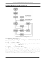
OPERATING MODES OF THE BATTERY BACK-UP
Figure 4: Diagram of operating modes
The NIEZNANY (UNKNOWN) mode
Intermediate state during the switching on of the battery back-up after the
back-up receives power.
The INIT mode (INITIALISATION)
Intermediate state occurring after the hardware platform is initialised with start
values or when returning from EMERGENCY mode.
The NORMAL mode (MAINS OPERATION)
For the battery back-up to operate in NORMAL mode it must be switched on
(from the user interface). Additionally, the basic mains input line must meet the
criteria of correct mains parameters (voltage and frequency). Only then will the
battery back-up transfer the power to the output from the above-mentioned mains
through the inverter system. In this mode accumulators are being charged.
2010/01/13
www.ever.eu
28
Instruction Manual for SUPERLINE series battery back-ups
The HYBRID (MIXED) mode
In the HYBRID mode the battery back-up provides power to the output from
the basic mains line while supplying the missing power from accumulators.
The BATTERY mode
If the basic mains input line or the BYPASS line in ECO mode fails to meet the
criteria of correct mains parameters, the battery back-up switches to the BATTERY
mode (battery operation). In the BATTERY mode the inverter provides power to the
accumulator output.
The ECO (ECONOMICAL) mode
Mode forced by the user by setting up the control flag (KONTROLA 2/4; ECO).
With the ECO control flag active the NORMAL and HYBRID modes are unavailable.
For the battery back-up to work in ECO mode the criteria of correct mains
parameters must be met for the basic and BYPASS lines. Incorrect parameters of
either line will cause the battery back-up to switch to BATTERY mode. With the ECO
flag set the battery back-up behaves similarly to an OFF-LINE type UPS. In ECO
mode the output is supplied with power from the BYPASS line or from the
accumulators (BATTERY mode). Internal power units are not involved in energy
processing, which increases the battery back-up’s efficiency.
The STOP mode
The battery back-up is switched off (from the user interface); no voltage
meeting the criteria of correct parameters is available on the basic line. It is also the
intermediate state when the battery back-up switches from BYPASS and
EMERGENCY modes.
The CZUWANIE (SLEEP) mode
The battery back-up is switched off (from the user interface); the basic line
meets the criteria of correct mains parameters. Battery preservation mechanisms are
active. When the battery back-up switches from STANDBY to SLEEP mode the
accumulator charge level is checked. If the charge level is below the set threshold
(KONFIGURACJA 3/4; Poj. z STB.), the battery back-up remains in this mode until
the required minimum charge is reached.
The STANDBY mode
The battery back-up may only switch to STANDBY mode from the BATTERY
mode when the accumulators are completely discharged or when forced by the user
(KONTROLA 2/4; UPS->STB). The mode switching is performed after the set time
has elapsed (KONFIGURACJA 2/4; Opoz.STB).
The battery back-up remains in this mode if the basic line voltage fails to meet the
criteria of correct mains parameters while the device is switched on.
Turning the battery back-up off causes it to switch to the STOP or SLEEP mode.
The BYPASS mode
The BYPASS mode is triggered when the battery back-up is overloaded or
when forced by the user (KONTROLA 3/4; UPS->BYPASS).
In such a case the output power is provided by the BYPASS line.
2010/01/13
www.ever.eu
29
Instruction Manual for SUPERLINE series battery back-ups
The device will return to normal operation when the load level drops below the set
threshold (KONFIGURACJA 3/4; ProgKas.Prz.).
The EMERGENCY mode
The EMERGENCY mode may be triggered by an overload, overheating or
turning on EPO. The battery back-up remains switched on but the processing blocks
are inactive. In this mode the BYPASS line is engaged. The only exception is the
battery back-up’s mode in which EPO is active when the BYPASS line is off.
OTHER FUNCTIONAL ELEMENTS
Safeguards
Against overloads
Overload (<105%) is signalled by a continuous sound and an appropriate message
on the display.
If the degree of overload remains at the level of 105÷120%, the battery back-up
continues to work in its current mode for another minute and then switches to the
BYPASS mode. If the overload exceeds 120% of the battery back-up’s nominal
power, the BYPASS mode is engaged immediately. The UPS remains in the
BYPASS mode as long as the load level exceeds the set threshold
(KONFIGURACJA 3/4; ProgKas.Prz.). When the load level returns below the
threshold the battery back-up will attempt five times to resume operation. Failure
causes the UPS to switch to the EMERGENCY mode. In the BATTERY mode an
overload will cause the battery back-up to switch to the EMERGENCY mode without
any additional attempts to resume operation.
Against shorting
In the inverter operation modes, i.e. NORMAL, BATTERY and HYBRID, the
electronic shorting safeguard reduces the short-circuit current to a safe level.
Shorting is signalled by an appropriate message and a quick intermittent acoustic
signal. If the shorting lasts longer than approx. 100 ms the battery back-up switches
to the EMERGENCY mode.
For operation modes utilising the BYPASS line circuit breakers F3 and F4 are used.
Figure 5: Input connectors with circuit breakers
2010/01/13
www.ever.eu
30
Instruction Manual for SUPERLINE series battery back-ups
Against overvoltage
The battery back-up is equipped with anti-overvoltage safeguard at the input which
protects the circuits of receivers and the internal circuits of the UPS against
overvoltage caused by atmospheric phenomena and power grid disturbances.
Accumulator safeguards
Accumulators are protected by fuses. The terminal of the external battery module
and the internal accumulators are safeguarded separately. These safeguards also
function as disconnecting switches used e.g. during installation. Fuse type is
presented in the technical parameters table.
WARNING! Do not use fuses other than provided for in the device’s
specification!
Figure 6: Safeguards of internal accumulators
Users must follow the instruction written in the label below the fuses which mentions
the necessity of maintaining correct order of engaging the fuses. Connect F1 first,
wait 10 seconds and then connect F2. Failure to follow this instruction may damage
the battery back-up.
Terminal of the external battery module is safeguarded by the F5 fuse located to the
right of the clamps. With the holder open it disconnects the poles.
Figure 7: Connections of the external battery module with the fuse
2010/01/13
www.ever.eu
31
Instruction Manual for SUPERLINE series battery back-ups
Thermal safeguards
The battery back-up is equipped with a thermal safeguard protecting it against
overheating. This safeguard operates on two levels.
If the internal temperature reaches critical, it switches on an acoustic signal and
displays the appropriate message. The UPS continues to operate in its current mode.
If the temperature keeps rising and critical temperature is reached, an alert is
displayed and the UPS switches to EMERGENCY mode.
EPO
EPO (Emergency Power Off) is a mechanism that enables interrupting the
power supply to receivers connected to the battery back-up’s output in emergency
situations (such as fires). The UPS switches to the EMERGENCY mode.
There are two ways to trigger this mechanism:
- By opening the contacts of the external EPO connector (release),
- By forcing the mode from the user interface (KONTROLA 1/4;
AwaryjneWylaczenie).
Output voltage returns after the user resets the malfunction flag (KONTROLA 3/4;
KasujAwarie) and moves the release to its inactive setting (default state of the
release) in the case of external triggering.
It is possible to temporarily lock the EPO function out while the EPO release is
installed. The technician may then remove the EPO connector without fear of cutting
the power supply to receivers. This operation must be completed within 1 minute
from the moment of setting the control flag (KONTROLA 2/4; Czas.Wyl.EPO);
afterwards the lock is automatically removed.
Voltage on the EPO contacts is safe and it is separated from all the other systems of
the UPS.
WARNING! The EPO circuit must be self-contained and must not be
connected to any other installations.
Manual BYPASS
The battery back-up is equipped with a manual switch for the BYPASS line, which
enables direct switching of the BYPASS line to the output clamps of the UPS,
circumventing the back-up units.
Figure 8: Manual BYPASS line switch
2010/01/13
www.ever.eu
32
Instruction Manual for SUPERLINE series battery back-ups
Switch in the UPS position – normal UPS operation
Switch in the BYPASS position – BYPASS line switched to output clamps. Switching
may be performed at any moment.
COMMUNICATION BETWEEN THE UPS AND A COMPUTER
COMMUNICATION VIA RS232 OR USB
Users have the option to change the battery back-up’s parameters not only via
the user interface (panel) but also via dedicated software.
SUPERLINE series battery back-ups come with enhanced control features. The UPS
is delivered with built-in RS232 and USB communication ports and the PowerSoft
Personal software package. In order to ensure correct cooperation the battery backup must be connected to the computer with the provided cable. After the cable is
connected, turn on the back-up, start the computer and install the software in
accordance with the instruction manual or the instructions provided by the installation
software (only Microsoft Windows).
WARNING! Only one type of connection may be used at any given
time.
RS232 and USB ports are separated galvanically from all the other units of the
battery back-up.
EVER SNMP/HTTP NETWORK CONTROL CARD
The EVER control card is an optional component that may be installed by the
user. It integrates the battery back-up with an Ethernet network. The network control
card is located in a special slot located on the rear panel of the battery back-up. With
the adapter installed the user can control the battery back-up from any computer
connected to the network. This solution is most often used in cases of central power
supply or when the power supply system needs to be controlled remotely.
The network control card has the following services implemented:
•
SNMP agent – enables control of the power supply system via a SNMP manager
software;
• HTTP server – enables inspection and modification of the battery back-up's
parameters via an Internet browser;
More information on the network card adapter can be found in its instruction manual.
WARNING! Installing the SNMP card renders the communication via
RS232 and USB, as well as control via PowerSoft Personal,
impossible.
2010/01/13
www.ever.eu
33
Instruction Manual for SUPERLINE series battery back-ups
Installing the control card
1)
2)
3)
4)
5)
6)
7)
8)
9)
10)
11)
12)
13)
14)
Turn off the battery back-up via the user interface (KONTROLA 1/4; UPS).
Set the F3 and F4 safeguards to OFF.
Disable the F1, F2 and F5 safeguards by opening the fuse holders.
Safeguards can be disabled in any order.
Wait approx. 30 seconds for the internal capacities to discharge.
Remove the screws holding the cover of the card slot.
Connect the cable located in the opening to the card.
Slide the card into the opening.
Replace the screws, fixing the card to the rear panel.
Enable the F1 safeguard by closing the holder.
Wait at least 10 seconds.
Enable the F2 safeguard by closing the holder.
Enable the F5 safeguard by closing the holder.
Switch the F3 and F4 safeguards to ON.
Launch the battery back-up via the user interface (KONTROLA 1/4; UPS).
Figure 9: Card installation
2010/01/13
www.ever.eu
34
Instruction Manual for SUPERLINE series battery back-ups
INSTALLATION AND CONFIGURATION OF THE POWERSOFT PERSONAL
SOFTWARE
Installation on computers with Windows
Prior to beginning the installation of PowerSoft:
•
•
Uninstall the current version of PowerSoft or any other control software (in
situations where the user is changing the battery back-up protecting the
computer),
If the battery back-up will communicate with the PC via a USB cable, this
cable should be disconnected from the computer. The software installer will
prompt the user to connect the communication cable at the appropriate time.
In order to install PowerSoft on a computer with Windows (the list of operating
systems compatible with the application is available at www.ever.eu) just run the
software installer and follow the instructions onscreen. During the installation you will
be asked to select the model of the battery back-up connected to the computer on
which the software is being installed. This setting may also be changed when the
application is running.
In the case of a UPS connected to the computer via a USB cable, when the
software installation is complete, the PowerSoft Personal installer will ask the user to
connect the USB cable to the computer. The system will announce that a new device
has been found and will propose to install the drivers. Select the option to install the
drivers from a chosen location and on the next screen indicate the installation folder
of the PowerSoft (usually C:\Program Files\PowerSoft) to be searched. Next,
the operating system will locate and install the appropriate driver.
In the case of Windows Vista the operating system will not launch automatic
installation of the drivers from the hard drive. After connecting the USB cable to the
computer you will need to open the control panel from the Start Menu and select
system properties. On the device tree displayed find the USB bus branch (in most
cases it will be already expanded) and select the battery back-up. Update the
device's driver from its "Properties" window by right-clicking it in the list and following
the instructions onscreen. As the driver's location you should indicate the PowerSoft
installation folder (usually C:\Program Files\PowerSoft).
To uninstall PowerSoft select the "Uninstall PowerSoft" option in Start Menu. You
can also uninstall PowerSoft from the "Add and remove programs" menu in the
control panel.
Installation on computers with Linux/Unix
The binary version of the application for Linux/Unix systems is provided in the
following formats:
CentOS, RedHat, Suse Linux, Fedora Core
For the CentOS, RedHat, Suse Linux, and Fedora Core systems the software is
provided in the form of a RPM package. The software can be installed by using any
package manager available for the system installed. If you are using the command
line the software is installed by entering the following command:
2010/01/13
www.ever.eu
35
Instruction Manual for SUPERLINE series battery back-ups
rpm -ivh powersoftpersonal-x.x.x.i386.rpm
Users working with the PowerSoft must have root privileges to install the software
and use it. After installation the application may be found in the /usr/local/powersoft
directory.
To uninstall the application enter the following command:
rpm -ev powersoftpersonal-x.x.x
Debian
For the Debian systems the software is provided in the form of a DEB package. The
software is installed via the following command:
dpkg --install powersoftpersonal-x.x.x.deb
To uninstall the application enter the following command:
dpkg --remove powersoft
FreeBSD
For FreeBSD systems the software is provided in the form of the default package
format designed for FreeBSD systems. The software is installed via the following
command:
pkg_add powersoftpersonal-x.x.x.tbz
To uninstall the application enter the following command:
pkg_delete powersoft
WARNING! FreeBSD systems do not support communication with
the UPS via the USB cable.
Starting the software
After installation the system service is started automatically, while the control panel
application can be found at /usr/local/powersoft.
Please note that for the Polish diacritics to be correctly displayed the system locale
should be Polish.
Software updates
Windows systems
The software installer for Windows systems has a built-in automatic updater.
PowerSoft may regularly check for new software versions and notify the user when
updates are available. By default the software check for updates after user log-in.
This setting may be changed in the "Update configuration" item in the system‘s
software menu.
2010/01/13
www.ever.eu
36
Instruction Manual for SUPERLINE series battery back-ups
Linux/Unix systems
In the case of Linux/Unix systems PowerSoft may be updated by downloading the
new package from www.ever.eu.
In the case of CentOS, RedHat, Suse Linux, and Fedora Core Powersoft may be
updated by entering the following command:
rpm -Uv powersoftlite-x.x.x
In the case of Debian and FreeBSD systems we recommend uninstalling the old
version and then installing the new version of the software. Commands which enable
these operations are described in the instruction manual available at www.ever.eu.
ADDITIONAL REMARKS
WARNING! Product for commercial and industrial applications in
secondary environment. Applying additional preventive measures or
limiters in the installation may be required in order to prevent the
emission of disturbances.
WARNING! No service elements located inside the battery back-up
are to be modified by the end user.
•
•
•
•
•
Damaging the warranty seal will void the warranty for the given device.
Any repairs should be conducted only by a qualified representative of the
technical support.
The battery back-up may not perform as expected if the powered equipment
draws high impulse power. In practice this means that even though mean power
of the protected equipment does not exceed the range of powers accepted by the
battery back-up, the equipment will cause the UPS to shut down. It happens
because the protected equipment temporarily draws power that significantly
exceeds the nominal power of the battery back-up, which causes a detection of
an overload and the resulting shutdown.
It is recommended that maintenance and inspection of accumulators be
conducted by competent personnel familiar with the device and following the
necessary precautions.
Accumulators should be replaced with accumulators of the same type and the
same number of cells or assemblies.
CAUTION! Keep the accumulators away from fire – they may
explode.
CAUTION! Do not open the accumulators and protect them against
damage. Spilled electrolyte is harmful to skin and eyes and may also
be toxic.
2010/01/13
www.ever.eu
37
Instruction Manual for SUPERLINE series battery back-ups
BATTERY BACK-UP AND POWER GENERATORS
The SUPERLINE-series battery back-ups are ONLINE class devices
synchronising with the mains voltage. By design the battery back-up to a certain
extent tolerates the changes in mains voltage and frequency in relation to the
nominal frequency of 50Hz (see the technical parameters table). When connected to
a power generator, the frequency variations change in time and are closely
dependent on changes in load levels. If the frequency variations of a power
generator's voltage exceed the allowed tolerance limit, the battery back-up will
consider such frequency to be incorrect and will switch to an appropriate operation
mode in accordance with the functionalities described above.
STORAGE, MAINTENANCE AND TRANSPORT
The battery back-up must be stored and transported in compliance with installation
guidelines present in a separate document delivered with the device. If these
requirements are not followed, EVER Sp. z o.o. shall not be responsible for any
mechanical damages that occur in transport.
DISPOSAL
Appropriate handling of used up electric and electronic equipment helps to avoid
consequences resulting from the presence of dangerous materials, as well as
inappropriate disposal and processing of such equipment, which may be hazardous
to human life and the environment.
Act dated 29 July 2005 on used-up electric and electronic equipment, article 22.1
items 1 and 2.
According to the regulations binding in the European Union, a
crossed rubbish bin symbol means that when a product is no longer
used it should be disposed of at a special waste pickup site. This
concerns the device itself, as well as other accessories marked with
this symbol. Do not dispose of those products together with
unsorted household waste.
Method of safe removal of the batteries from the appliance:
The batteries should be removed from the appliance by an authorised service outlet
or by a duly authorised electrician.
2010/01/13
www.ever.eu
38
Instruction Manual for SUPERLINE series battery back-ups
TECHNICAL PARAMETERS
INSTALLATION GUIDELINES
Parameter \ Battery back-up
Apparent / active power
SUPERLINE
model 6k
SUPERLINE
model 8k
SUPERLINE
model 10k
SUPERLINE
model 12k
6 kVA
4.8 kW
8 kVA
6.4 kW
10 kVA
8 kW
12 kVA
9.6 kW
38 A
46 A
Power supply parameters
Power supply system topology
1P3W
Nominal voltage
230 V
Nominal current
23 A
31 A
Nominal input frequency
6 mm2
10 mm2
10 mm2
10 mm2
Switch fuse
40 A gG
63 A gG
80 A gG
80 A gG
Switch fuse
40 A gG
63 A gG
80 A gG
80 A gG
Minimum cable section
Basic and
BYPASS lines
safeguards
50 Hz
Output parameters
Output system topology
1P3W
Nominal output voltage
Nominal current
Minimum cable section
Output line
safeguards
Switch
disconnector
230 V
21 A
28 A
35 A
42 A
6 mm2
10 mm2
10 mm2
10 mm2
40 A
63 A
80 A
80 A
<1650 BTU
<2200 BTU
<2800 BTU
<3300 BTU
Environment parameters
Amount of heat generated in nominal
operating conditions
Operating temperature
10 ÷ 40 °C
Storage temperature
0 ÷ 40 °C
Humidity
Altitude (above sea level)
< 95 %
< 1000 m
Mechanical parameters
Dimensions
(w x d x h)
Weight
Free space requirements
2010/01/13
340x740x795mm
200 kg
front: > 200 mm
sides: > 100 mm
rear: > 300 mm
www.ever.eu
39
Instruction Manual for SUPERLINE series battery back-ups
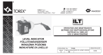
TECHNICAL DATA
PARAMETERS \ MODEL
Output power 1)
GENERAL INFORMATION
Topology
Overall efficiency for Pmax (for VFI)
Overall efficiency for Pmax (for ECO)
Cooling
Degree of protection
Working environment
Operating temperature 2)
Storage temperature
Relative humidity for operation
Relative humidity for storage
Altitude (above sea level) 3)
RECTIFIER
Input voltage
Frequency of input voltage
Power Factor (PF)
Total harmonic distortion of input current
(THDi)
Safeguards
INVERTER
Output voltage (effective value)
Shape of output voltage
Frequency of output voltage
Static control of voltage
Total harmonic distortion of output voltage
(THDu)
Peak factor
Short-circuit current
Safeguards
SUPERLINE
model 6k
6 kVA
4.8 kW
SUPERLINE
model 8k
8 kVA
6.4 kW
SUPERLINE
model 10k
10 kVA
8 kW
SUPERLINE
model 12k
12 kVA
9.6 kW
VFI
> 93 %
> 98 %
Forced, internal fans
IP20
Dedicated rooms with low pollution level
10 ÷ 40 °C
0 ÷ 40 °C
< 95 %
< 95 %
< 1000 m
~70 ÷ 280 V ± 2 %
45 ÷ 55 Hz ± 1 Hz
> 0.99
< 3%
Overcurrent switches for the basic and BYPASS lines 2 x 63 A (ch.B)
~230 V ± 2 %
Sinus
Synchronous / 50Hz ± 0.2 Hz
<1%
< 1,5 % for Pmax (line)
< 5 % for Pmax; CF = 2.2; PF=0.65)
5:1
> 5 IN
Inverter operation – electronic safeguards against shorting and overloads
BYPASS line operation – output overcurrent safeguards
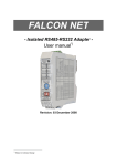
ACCUMULATORS
> 12/21/35 min
> 24/32/54 min
1 x 28 x VRLA 12 V / 7 Ah
2 x 28 x VRLA 12 V / 7 Ah (option)
> 9/12/25 min
> 7/10/15 min
> 17/22/40 min
> 13/17/30 min
> 7/10/12 min
> 10/14/25 min
> 72/95/180 min
> 50/72/125 min
> 40/51/92 min
> 30/42/74 min
4)
< 2h
< 2h
< 2h
< 2h
Maximum charging time of 1 module
(after discharging with power of 80% Pmax)
< 3h
< 3h
< 3h
< 3h
Battery back-up’s accumulators
Support time with internal batteries only
(100%/80%/Pmax)*
Support time with 1 battery module installed
(100 % / 80%/50% Pmax)
Maximum charging time of internal batteries
4)
MECHANICAL PARAMETERS
Dimensions (w x d x h)
340x740x795mm
UPS weight
200 kg
EQUIPMENT
Connectors
Screw terminals; max. 16 mm2 (line)
Signalling
Acoustic and visual, LCD display
Communication interface
RS232, USB, SNMP/HTTP network control card - optional
EPO
Available
Manual BYPASS switch
Available
Note: The manufacturer reserves the right to change the abovementioned parameters without notice.
Notes:
1)
For normal operation of the battery back-up the load connected to its output should not exceed 80% of value indicated in the table. Reserve power is essential to
ensure continuous operation of connected devices in case of momentary rushes in load current.
2)
Continued exposure of the battery back-up to the temperature of the surrounding exceeding +25°C will shorten the life of batteries.
3)
If the altitude above sea level increases beyond the provided limit the permitted load power of the batter back-up decreases.
4)
Time to charge the batteries to 90% capacity after discharging them with load of 80% Pmax
5)
Sample battery module in a typical configuration.
2010/01/13
www.ever.eu
40
Instruction Manual for SUPERLINE series battery back-ups
INFORMATION REGARDING REGULATIONS AND
WARRANTY
DECLARATION OF CONFORMITY
The battery back-up was manufactured in Poland and its structure conforms to
appropriate subject matter standards.
WARRANTY
A separate document attached to the product constitutes the warranty. The
document must meet all formal requirements (e.g. date of sale, dealer stamp).
The manufacturer made all efforts to ensure that products offered are free of material
and workmanship defects throughout the term specified in the warranty document.
The company's liability under the warranty is limited to repairs or replacement of
products with such defects. The manufacturer shall make the decision as to how the
defect is removed. The warranty does not cover devices with mechanical damages
that occurred as a result of negligence of incorrect use or devices subjected to any
modifications made by the user.
Apart from the arrangements included in the warranty card EVER Sp. z o.o. does not
grant any guarantee or warranty, including warranty of merchantability or fitness for
particular purpose.
Apart from the arrangements included in the warranty card EVER Sp. z o.o. shall not
be liable for direct, indirect, specific, incidental or consequential losses incurred in the
course of using the battery back-up, even in cases when the buyer was warned
about such losses being a possibility. The company shall not be liable for any costs,
such as loss of profit or revenue, cost of equipment, costs of equipment use, costs of
software, data, replacement products, and claims of third parties or other costs.
2010/01/13
www.ever.eu
41