1
Black Max™ Amplifier
X300, X450, & X600 Models
Installation and Use Manual
© 2005 Bogen Communications, Inc.
All rights reserved.
54-2063-01D 0910
Notice
IMPORTANT
Every effort was made to ensure that the information in this
guide was complete and accurate at the time of printing.
However, information is subject to change.
Important Safety Information
WARNING: To Reduce The Risk of Fire Or Electric Shock,
Do Not Expose This Apparatus To Rain Or Moisture.
Always follow these basic safety precautions when installing and
using the unit:
1.
2.
3.
4.
5.
6.
7.
8.
9.
10.
11.
12.
13.
Read these instructions.
Keep these instructions.
Heed all warnings.
Follow all instructions.
Do not use this apparatus near water. The apparatus shall
not be exposed to dripping or splashing and no objects filled
with liquids, such as vases, shall be placed on the apparatus.
Clean only with dry cloth.
DO NOT block any ventilation openings. Install in
accordance with the manufacturer’s instructions.
Do not install near any heat sources such as radiators, heat
registers, stoves, or other apparatus (including amplifiers)
that produce heat.
Do not defeat the safety purpose of the polarized or
grounding-type plug. A polarized plug has two blades with
one wider than the other. A grounding-type plug has two
blades and a third grounding prong. The wide blade, or the
third prong, are provided for your safety. If the provided
plug does not fit into your outlet, consult an electrician for
replacement of the obsolete outlet.
Protect the power cord from being walked on or pinched,
particularly at plugs, convenience receptacles, and the point
where they exit from the apparatus.
Only use attachments/accessories specified by the manufacturer.
Unplug this apparatus during lightning storms or when
unused for long periods of time.
Refer all servicing to qualified service personnel. Servicing is
required when the apparatus has been damaged in any way,
such as power-supply cord or plug is damaged, liquid has
been spilled or objects have fallen into the apparatus, the
apparatus has been exposed to rain or moisture, does not
operate normally, or has been dropped.
Domestic and International Listings
UL and C-UL Listed.
i
CAUTION: TO PREVENT THE RISK OF ELECTRIC SHOCK, DO NOT REMOVE COVER (OR
BACK). NO USER-SERVICEABLE PARTS
INSIDE. REFER SERVICING TO QUALIFIED
PERSONNEL.
The lightning flash with arrowhead symbol, within an equilateral triangle, is intended to alert
the user to the presence of
uninsulated “dangerous voltage”
within the product’s enclosure
that may be of sufficient magnitude to constitute a risk of electric shock to persons.
The exclamation point within an
equilateral triangle is intended
to alert the user to the presence
of important operating and
maintenance (servicing) instructions in the literature accompanying the appliance.
Contents
Page
INTRODUCTION................................................................................................................1
Package Contents ........................................................................................................................................1
PANEL DESCRIPTIONS ................................................................................................2-3
Black Max Front Panel ................................................................................................................................2
Black Max Rear Panel..................................................................................................................................3
INSTALLATION ..............................................................................................................4-5
Mechanical Components ............................................................................................................................4
Ventilation......................................................................................................................................................5
Rack Mounting ..............................................................................................................................................5
Rear Rack Mounting....................................................................................................................................5
Table Mounting ............................................................................................................................................5
CONNECTIONS..................................................................................................................6
Speakers ........................................................................................................................................................6
Inputs ..............................................................................................................................................................6
AC Power......................................................................................................................................................6
SEQUENTIAL TURN-ON..........................................................................................................................7
Sequential Turn-On Operation ................................................................................................................7
OPERATION ....................................................................................................................8-9
Front Controls & Indicators ....................................................................................................................8
Rear Controls & Indicators ......................................................................................................................8
TROUBLESHOOTING ....................................................................................................10
SPECIFICATIONS ............................................................................................................11
LIMITED WARRANTY; EXCLUSION OF CERTAIN DAMAGES..............................12
ii
iii
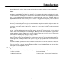
Introduction
Bogen's Black Max™ amplifiers deliver on what professional sound installers need most: Power and Reliability.
Power
With three different models (X600, X450, and X300), the Black Max series provides 2 independent channels of
amplification at 600W, 450W, and 300W per channel into 70V constant-voltage speaker loads safely and securely.
Located on the rear of the amplifier are the Level Controls, Low Cut Filter Switch, and pluggable input terminal
strip for each amplifier channel. These amplifiers are powerful (with total system power of 1200W, 900W and
600W with both channels driven), but they are also compact — using up only 2 rack spaces (3-1/2") in a standard
19" rack.
Reliability and Functionality
Driven by a conservatively-rated toroidal power transformer, these amplifiers are built for solid performance with
low distortion and a high slew rate. The amplifiers require little maintenance and cleaning as internal electronic
components are located outside of the forced air stream flow. Front-mounted fan filters provide easy removal
and cleaning.
Black Max amplifiers have a variety of electronic protection circuits including overcurrent, DC voltage, and thermal
circuits. A special Clip/Limiting circuit continuously monitors the amount of distortion in the output signal and
reduces input levels as the amplifier approaches clipping. Back-Slope™ AC Voltage Stabilization, Bogen’s unique
voltage stabilization circuitry, regulates the AC energy supplied from the power toroid. This improves both system
performance and reliability despite varying AC supply conditions.
An energy-conserving sleep mode (defeatable) with instant-on return signal operation reduces wasted heat production in paging systems with intermittent use. In addition, large output heat sinks and dual independently-controlled, high-output, variable speed fans provide superior cooling and quiet operation while reducing dust accumulation.
A simple and reliable sequential turn-on feature minimizes in-rush current from the AC power mains. When multiple Black Max amplifiers are daisy-chained together for sequential turn-on, the first amplifier in the series will control the powering up of the other amplifiers with approximately 1 second of delay between units. Turning off the
first amplifier causes all amplifiers to turn off.
Package Contents
* Black Max Amplifier (Model X600, X450, or X300)
* 2 Rack Ears for Mounting
* 2 Filters and Grilles
* Instruction Manual
* 4 Rubber Feet & Screws
* 2 Three-position, 1 Four-position Terminal Strips
1
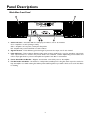
Panel Descriptions
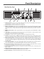
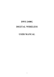
Black Max Front Panel
1. Status Indicators - The Status LEDs are multi-purpose indicators, one for each channel.
Green - Amplifier is on and operating normally.
Amber - Amplifier is in low-power consumption Sleep Mode.
Red - Amplifier has protected itself due to a fault condition.
2. Signal Indicators - These illuminate green when signal is present at the output, one for each channel.
3. Limit Indicators - These indicators illuminate amber when excessive signal levels or very low impedance output loads
cause output distortion to exceed a few percent. Under such conditions, a built-in Clip/Limiting circuit activates and
reduces input signal levels to protect both amplifier and speaker loads. One for each channel.
4. Power Switch/Circuit Breaker - Magnetic circuit breaker controls AC power to the amplifier.
5. Fan Air Intake and Grilles - Air intakes for 2 independent, variable-speed cooling fans. Each responds as needed to
keep the amplifier cool while reducing dust build-up. Removable fan grilles are provided to allow access to the dust filters
for cleaning.
2
Panel Descriptions
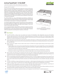
Black Max Rear Panel
1. Speaker Terminals - Connects to 70V constant voltage speaker loads. One set for each amplifier section. Accepts up
to #10 AWG wire or spade lugs for speaker system connections.
2. Ground Terminal - Provides convenient access to earth ground.
3. Automatic Sleep Mode - Allows the unit to automatically put itself into a sleep mode when there has been no input
activity for more than 3 minutes. In sleep mode, the amplifier’s idle power is greatly reduced. The amplifier immediately
and noiselessly returns to its full-powered state when a signal is detected at an input. Flush switch actuators reduce tampering.
4. CH B Input Select Switch - Allows output Channel B to source its input signal from either "A BAL INPUT" or "B BAL
INPUT".
5. Lo-Cut Filters - Roll off frequencies below 60 Hz (2nd order) to prevent saturation of speaker transformers. Flush
switch actuators reduce tampering. One per channel, high pass.
6. Fan Exhausts - Cooling air outlets for independent, variable speed cooling fans. One per channel.
7. Line Cord - AC mains input line cord. Note: The X600 requires a 20A, 125V AC power receptacle because its maximum current requirements exceed the capacity of a typical 15A receptacle. The 20A receptacle is a NEMA 5-20R style.
8. AC Power Status Indicator - Indicates the AC power status of the Black Max amplifier. When the indicator is not lit,
no AC power is applied to the line cord. When lit amber, power is applied to the line cord but no sequential trigger has
been received to place the amplifier into a fully powered-up state (or power switch is OFF). When lit green, the amplifier is fully powered.
9. Power Sequencing Switch - Turns power sequencing ON or OFF so that an amplifier can be controlled by either its
front circuit breaker switch or by another Black Max amplifier. Flush switch actuators reduce tampering.
10. Power Sequencing Inputs - Multiple Black Max amplifiers can be wired together in a daisy chain to allow for controlled
sequential power-up. A pluggable screw terminal strip is provided for easy installation.
11. Input Sensitivity Switch - Allows the unit to reach full power at either line-level input (1V) or low-level input (0.1V).
One per channel.
12. High-Impedance Balanced Inputs - Pluggable 3-position screw terminal strips allow for easy installation and provide
convenient connections to high-impedance balanced inputs. One per channel.
13. Input Level Controls - Continuously variable input level controls. One per channel.
3
Installation
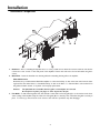
Mechanical Components
1. Rack Ears - Prior to installing the amplifier into a 19" rack, you will need to attach the rack ears. Remove and save the
6 front-most cover screws on each side panel of the amplifier. Position the rack ears as shown and attach using the 6
screws.
2. Dust Filter - Insert the dust filter into the fan grille before attaching the fan grille to the amplifier.
Filter Maintenance
Dust filters are provided with the Black Max amplifier to reduce the build up of dust on the heat sinks. Periodic cleaning should be done when there is a noticeable build up of dust on the filters. To clean the filters, remove them from
the grilles and wash, vacuum, or tap them out. Promptly replace them.
Caution:
The fan blades are accessible when the grille cover and filter are removed.
Be careful not to place your finger or other objects into the fan.
3. Fan Grille - To attach the fan grilles: first, slide the tabs on the wider end of the grille (A) in to the notches in the front,
center casting of the amplifier. Snap the other end of the grille (B) in to the snap slots. Check that the grille is securely in
place. To remove, pry the end of the cover closest to the rack ears up until the snap tabs disengage.
4
Installation
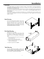
Ventilation
The Black Max amplifiers were designed to be placed on a table or rack-mounted. For rack-mounted applications,
the amplifiers can be stacked one on top of the other for maximum use of the rack space available without any
extra, empty rack spaces between them.
An open air space of at least 4" must be provided at the front air intakes of the amplifier and the rear exhaust must
have at least 4" between itself and obstructions to ensure adequate cooling. This applies whether rack- or
table-mounted.
Care should also be taken to ensure that the front intake air is not considerably warmer than the ambient air temperature. Mount the amplifiers low in the rack so that heat dissipation from other equipment does not warm the
amplifier's intake air.
Rack Mounting
Rack ears are included with the amplifier to allow mounting in 19" racks. Attach the rack ears as shown in the
Mechanical Components section. If any feet have been
attached to the bottom of the amplifier, remove them.
Load the amplifier into the rack and secure it to the rack
with appropriate hardware (not included).
Rear Rack Mounting
(Optional accessory, not included)
For greater rear support when rack-mounting a Black
Max amplifier, the RPK86 Rack Mounting Kit can be
attached to the rear of the amplifier by following these
steps:
1. Remove and save the three rear-most cover screws
from the chassis side.
2. Position the rack attachment as shown.
3.
Replace and tighten the three cover screws to
secure the rack attachments.
4.
Repeat on opposite side of amplifier.
Table Mounting
Feet are provided with the amplifier to allow it to be
placed on a tabletop. Attach the included feet to the bottom of the amplifier as shown. Attachment of the rack
ears to the unit is optional and purely aesthetic.
5
Connections
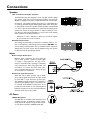
Speakers
70V "Transformer-Coupled" Speakers
The Black Max series was designed to drive only 70V constant voltage
type speaker loads. The use of low-impedance speakers may cause the
amplifier to engage its protection circuits and shut down or limit amplifier function. The speaker terminals can accept up to a #10 AWG wire
or spade lug and have integral clamping plates which make wiring easier. The polarity of each set of speaker outputs (A & B) is indicated with
a "+" and "-" sign. Use these indicators to ensure that the phasing of the
speakers are correct. Do not ground the "+" output of either set of outputs. Doing so will cause the amplifier to go into protect mode, shutting
down operation of the affected channel.
Note: The "+" and "-" indicators are mirrored on "A" and "B" outputs.
Be sure to make the correct connections.
Earth Ground Terminal
The earth ground terminal is provided as a convenient means to connect to the amplifier’s chassis/AC ground, if necessary. DO NOT connect the earth ground terminal to the "+" terminals of either output. No
damage will occur if this is done, but the amplifier will go into protect
mode and shut down the affected channel.
Inputs
Balanced Input Connections
Balanced input connections are used when the
source device provides a balanced output (signal
"+", signal "-", and ground "G"). This type of connection is desirable when operating in electrically
noisy environments, where long input cable runs
are needed, or to ensure the lowest noise operation. If compatible with the source device, this type
of connection is recommended.
Unbalanced Input Connections
When the source device provides only an unbalanced output (signal and ground), the input should
be wired with "-" input shorted to ground ("G").
The unbalanced signal's shield wire is connected to
ground and the signal hot wire is connected to the
"+" terminal. Since unbalanced connections do not
provide the same amount of noise immunity that a
balanced connection does, the connection distances
should be made as short as possible.
AC Power
20A AC Receptacle
The X600 line cord requires a 20A, 125V AC power
receptacle because its maximum current requirements exceed the capacity of a typical 15A receptacle. The 20A receptacle is a NEMA 5-20R style.
6
G
W
Sequential Turn-On
Sequential Turn-On Operation
Black Max amplifiers contain a sequential turn-on feature that is designed to turn on a bank of Black Max amplifiers,
one at a time, in sequence with approximately 1 second between each amplifier. This type of sequencing of power
is necessary in large systems where the in-rush current of all the system amplifiers turning on at once would overload the AC mains supplying the system.
The first amplifier in the chain will act as the master amplifier controlling the power-up for the group. When it is
switched on, it will initiate the power-up sequence.
To prepare/wire multiple Black Max amplifiers for sequential turn-on operation, do the following:
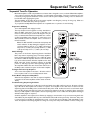
Preparation & Wiring
Turn off all amplifiers and unplug from AC.
The amps should be wired together in a daisy chain fashion.
Wire the XMT connections of one amp to the RCV connections of the next amp as shown in the diagram. This pattern is continued until all the desired amplifiers are connected. The last amplifier in the chain has no connections on its
XMT terminals, and the first amplifier has no connection to
its RCV terminals.
Note: The RCV and XMT terminals have both polarity and
number indicators. In daisy chaining the amplifiers, the same
connection pattern is used: Pin 4 ("+") XMT of the previous
amp to Pin 2 ("+") RCV of the next amp and Pin 3 ("-") XMT
of the previous amp to Pin 1 ("-") RCV of the next amp.
Switch Settings
The position of the Power Sequencing Switch of the Black
Max is important in sequencing setup. The master amplifier’s
Power Sequencing Switch MUST be set to OFF. By setting
the switch to OFF, this amplifier will turn on and off directly by its front Power Switch. All other amplifiers in the chain
MUST have their Power Sequencing switches in the ON
position so that they respond to the sequencing signals. All
slave amplifiers MUST have their front Power Switch set to
the ON position, with the exception of the master amplifier.
To Begin the Power Up Sequence
Turn on the first amplifier in the chain. All others will follow in sequence with a 1 second delay between them.
Power Down of Sequenced Amplifiers
When the first amplifier in the chain of sequenced amplifiers
is switched off, all other amplifiers will also switch off immediately.
Troubleshooting Sequencing Problems
If an amplifier in the chain does not have its front Power Switch set to ON, it will not power up. However, all other
amps that follow that amplifier will continue to sequence. If an amplifier in the chain does not have its Power
Sequencing Switch in the ON position, it will break the daisy chain. It will, in effect, become a second master amplifier controlling all amps that follow it. In this case, if the Power Switch for this amp is switched off, the sequencing
will stop at that amplifier. If this amplifier’s Power Sequencing Switch is set to ON, then all amplifiers following it
will have already begun to sequence.
Should an amplifier in the sequence shut off either by tripping its circuit breaker or by someone turning the Power
Switch OFF, only that amplifier will lose power. All units that follow will remain powered up. If however, AC power
is removed from an amplifier by unplugging the power cord, all other amps following it will immediately power
down. An amplifier in the chain going into or coming out of low-power sleep mode will have no effect on the group.
7
Operation
Front Controls & Indicators
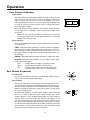
Power Switch
The Power Switch for the Black Max amplifier is located on the front of the
unit. Press the "I" side of the switch to turn the unit ON. The amplifier will
begin its power-up process once turned on. If the amplifier is set up for
power sequencing (see the section on power sequencing), the amplifier may
not begin its power-up process but rather wait in a standby state until it
receives a sequence trigger.
The Power Switch is also the amplifier’s circuit breaker. Should the breaker trip, simply place it in the OFF position and then back to ON to reset
the breaker.
Note: If the Power Sequencing Switch is in the ON position, but the wiring
is not properly configured, the unit will appear dead. Review the Sequential
Turn-On section for proper wiring.
Front Indicators
The front of the Black Max amplifier contains 3 different types of indicators
for each channel.
LIMIT - When illuminated, it indicates a condition in which the amplifier is
limiting and automatically reducing signal level to reduce the overload condition. Limiting is a result of speaker load impedances that are too low or
input signals that are too high, which drive the outputs beyond their operational ranges.
SIGNAL - When illuminated, it indicates that there is signal at the output.
STATUS - Illuminates in three different colors to indicate current operational status of the amplifier.
Green Amber Red -
Indicates that the amplifier is operating normally.
Indicates that the amplifier is in Sleep mode.
Indicates a fault condition and that the amplifier has
disconnected the output load as a safety precaution.
Rear Controls & Indicators
Level Controls
Use the rear-mounted Level Controls on the Black Max amplifier to adjust
output volume of each channel independently.
Lo-Cut Switch
The Low Cut Filter allows a low frequency roll-off starting at 60 Hz to be
introduced into the signal path preventing the speakers from receiving too
much low frequency content. The Low Cut Filter Switch should be turned
ON when using typical inexpensive, transformer-coupled cone-type speakers found in paging systems.
The Black Max amplifier is a direct-coupled amplifier, which means that
there are no output transformers used to deliver the 70V audio to the
speakers. Because of this, the Black Max amplifier has a flat frequency
response down to and below 20 Hz. This extended low frequency operation can be troublesome for some transformer-coupled speakers used in
70V audio systems. Relatively inexpensive transformers used in some speakers cannot handle frequencies below 60 Hz. When frequencies lower than
this are applied to these speakers’ transformers, they can saturate causing
distortion and high instantaneous power consumption.
8
I
O
Operation
Sleep Switch
The Black Max amplifier includes a sleep mode feature that greatly reduces
the power consumption of the amplifier after it has been idle (no audio
activity) for more than 3 minutes. Any audio activity present at the input
will power up the amplifier instantaneously and noiselessly, so that there is
no loss of audio. The Sleep Switch is located on the rear of the unit. The
sleep feature is activated by setting the switch to the AUTO position.
Setting the switch to the OFF position will inhibit the amplifier from ever
entering sleep mode.
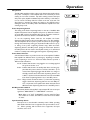
Power Sequencing Switch
The setting of the Power Sequencing Switch on the rear of the Black Max
amplifier determines how the amplifier will power up. When the switch is
set to the OFF position, the amplifier will power up and down conventionally when the front Power Switch is turned ON and OFF.
To use the sequencing feature built into the amplifier, the Power
Sequencing Switch must be placed in the ON position on a slave amplifier.
The slave amplifier will now power up when it receives the proper trigger
through the terminal strip wiring (see Sequential Turn-On section for proper wiring of the power sequencing terminal strip). With the Power
Sequencing Switch in the ON position, placing the front Power Switch in
the ON position will not result in the amplifier turning on. It will instead
remain in a standby state until triggered through the sequencing feature.
Power Status Indicator
A Power Status Indicator is provided on the rear of the amplifier. The Black
Max amplifier has different states of powering up, depending on whether
power sequencing is used or not. The Power Status Indicator provides 3
different status indications:
Not Lit - Indicates that the unit is not plugged in or is not being supplied
AC power at the line cord.
Amber - Indicates that the unit is in standby state where it is being supplied with AC power at the line cord but it has either: 1) not
received the sequencing trigger that will allow it to change to
the fully-powered state if the Power Sequencing Switch is set
to ON, or 2) the front Power Switch has not been turned ON
if the Power Sequencing Switch is set to the OFF position.
Green - Fully-powered, the unit has either: 1) received the sequencing
trigger if the Power Sequencing Switch is set to the ON position, or 2) the unit’s front panel Power Switch has been turned
ON if the Power Sequencing Switch is set to the OFF position.
CH B Input Select Switch
Determines whether the amplifier's output channel 'B' sources its input
signal from "B BAL INPUT" or "A BAL INPUT" connectors.
Note: When set to "IN A", "B BAL INPUT" connector and CH B "Input
Sens" Switch are not active, but CH B level control and Low Cut Switch
are active.
Input Sensitivity Switch
Each input has a user-selectable sensitivity switch. When operating
with standard line-level source equipment, the input should be set for
1V. When operating with low-level source equipment, the input
should be set for 0.1V.
9
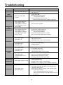
Troubleshooting
PROBLEM
UNIT APPEARS
DEAD
(NO FRONT
STATUS LED)
SEQUENCING
NOT
FUNCTIONING
CORRECTLY
CONDITION
CAUSE
Rear Power Status LED is off.
• Amplifier not plugged in
• AC outlet dead
Rear Power Status LED
is amber.
• Power Switch OFF
• Breaker (Power Switch) tripped
- Turn off, then turn back on
• Power Sequencing Switch set wrong
- Check Sequential Turn-On section for proper configuration
Master amplifier ON (Rear
Power Status is green),
slave amplifiers in chain not
powering ON (Rear Power
Status is OFF).
• No AC power to amplifier
Master amplifier ON (Rear
Power Status is green),
slave amplifiers in chain not
powering ON (Rear Power
Status is amber).
• Power Switch is OFF on slave amp
• Breaker (Power Switch) tripped
- Turn off, then turn back on
• Rear Power Sequencing Switch is not ON
• Error in Sequencing wiring between amplifiers
Status LED is green.
Signal LED is off.
• Level Controls turned down
• No signal from source
• CH B Input Select not set or wired properly
Status LED is green.
Signal LED is green.
Limit LED is off.
• Poor/broken speaker wiring
• Defective speakers
Status LED is green.
Signal LED is green.
Limit LED is off.
•
•
•
•
Status LED is green.
Signal LED is green.
Limit LED is amber (on or
flashing).
• Speaker transformers saturating at low frequencies, Low Cut
filter off, need additional Hi-Pass filtering
• Below minimum load rating on output
• Exceeding maximum power output rating
Status LED is red/green cycling.
•
•
•
•
Status LED is green.
Signal LED is green.
• Poor electrical connections at input
• Input cable routed near AC cables, power transformer, or
other EMI radiating devices
• Electrically noisy devices operating on the same AC circuit
• Poor equipment grounding
- Ensure that all AC safety grounds are connected
- Make sure that all components in audio chain are tied to the
same ground
NO SOUND
DISTORTED
SOUND
INTERMITTENT
OPERATION
NOISE/HUM
Input signal level too high
Poor speaker connections
Low Cut Switch set to Flat
Input Sensitivity Switch not set correctly
DC level at signal input
Load impedance too low
Amplifier speaker output is short-circuited
Amplifier too hot (check for proper ventilation clearances)
10
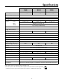
Specifications
Power Output*
X600
X450
X300
600W / Ch @ 70V
450W / Ch @ 70V
300W / Ch @ 70V
Input Sensitivity (selectable)
1V/0.1V
S/N Ratio (20 kHz BW)
104 dB ref. 70V, F.P.
Class of Operation
Connector:
H
Power
20A line cord**
15A line cord
Input
Pluggable 3-pin terminal strips
Output
5-pin "touch-proof" Barrier Strip
Power Bandwidth
20 Hz - 40 kHz, < 0.5% THD
less than .02%
THD @ 1 kHz Rated Power
Rated Load Impedance (per Ch.)
8 ohms
11 ohms
Output Regulation
1.5 dB @ 70V
100k-ohm electronically balanced, 3-pin pluggable terminal strip
Low-Cut Filter
60 Hz, 2nd order roll-off, switch defeatable per channel
AC Input Voltage Range
AC Current Rating (full power)**
95-130V AC, 60 Hz
20A**
15A
AC Voltage
Status, Limit, Signal, AC Power Status (Rear)
Temperature Range
15° to 105° F
1667 BTU/Hr
Cooling
1537 BTU/Hr
Protection
Special Features
1195 BTU/Hr
Dual Forced Air Variable Speed Fan
Physical Dimensions (W x H x D)
Product Weight
12A
120V AC, 60 Hz
Indicators
Thermal Emissions (Full Power)
16 ohms
20 Hz - 20 kHz ± 0.25 dB
Frequency Response @ 1 watt
Inputs
15A line cord
17" W x 3-1/2" H x 18-1/4" D
46 lb.
44 lb.
41 lb.
RF, DC, Low frequency, Thermal, Low impedance, Circuit Breaker, Short Circuit
Sequential Turn-On Circuitry (defeatable), Sleep Mode (defeatable),
Back-Slope™ AC Voltage regulation, Toroidal Power Transformer, Input Sens, CH B Input Select
* Both channels driven at nominal line voltage 120V AC, 60 Hz.
** The X600 requires a 20A, 125V AC power receptacle because its maximum current requirements
exceed the capacity of a typical 15A receptacle. The receptacle is a NEMA 5-20R style (right).
11
G
W
Limited Warranty; Exclusion of Certain Damages
Bogen Black Max™ amplifiers are warranted to be free from defects in material and workmanship for three (3) years
from the date of sale to the original purchaser. Any part of the product covered by this warranty that, with normal installation and use, becomes defective (as confirmed by Bogen upon inspection) during the applicable warranty period, will
be repaired or replaced by Bogen, at Bogen’s option, provided the product is shipped insured and prepaid to: Bogen
Factory Service Department, 50 Spring Street, Ramsey, NJ 07446, USA. Repaired or replacement product will be
returned to you freight prepaid. This warranty does not extend to any of our products that have been subjected to abuse,
misuse, improper storage, neglect, accident, improper installation or have been modified or repaired or altered in any
manner whatsoever, or where the serial number or date code has been removed or defaced.
THE FOREGOING LIMITED WARRANTY IS BOGEN’S SOLE AND EXCLUSIVE WARRANTY AND THE PURCHASER’S SOLE AND EXCLUSIVE REMEDY. BOGEN MAKES NO OTHER WARRANTIES OF ANY KIND, EITHER
EXPRESS OR IMPLIED, AND ALL IMPLIED WARRANTIES OF MERCHANTABILITY OR FITNESS FOR A PARTICULAR PURPOSE ARE HEREBY DISCLAIMED AND EXCLUDED TO THE MAXIMUM EXTENT ALLOWABLE BY
LAW. Bogen's liability arising out of the manufacture, sale or supplying of products or their use or disposition, whether
based upon warranty, contract, tort or otherwise, shall be limited to the price of the product. IN NO EVENT SHALL
BOGEN BE LIABLE FOR SPECIAL, INCIDENTAL OR CONSEQUENTIAL DAMAGES (INCLUDING, BUT NOT
LIMITED TO, LOSS OF PROFITS, LOSS OF DATA OR LOSS OF USE DAMAGES) ARISING OUT OF THE
MANUFACTURE, SALE OR SUPPLYING OF PRODUCTS, EVEN IF BOGEN HAS BEEN ADVISED OF THE
POSSIBILITY OF SUCH DAMAGES OR LOSSES. Some States do not allow the exclusion or limitation of incidental
or consequential damages, so the above limitation or exclusion may not apply to you. This warranty gives you specific
legal rights, and you may also have other rights which vary from State to State.
Products that are out of warranty will also be repaired by the Bogen Factory Service Department – same address as
above or call 201-934-8500. The parts and labor involved in these repairs are warranted for 90 days when repaired by
the Bogen Factory Service Department. All shipping charges in addition to parts and labor charges will be at the owner's
expense. All returns require a Return Authorization number. For most efficient warranty or repair service, please include
a description of the failure.
12/2008
50 Spring Street, Ramsey, NJ 07446, USA
Tel: 201-934-8500; Fax: 201-934-9832
www.bogen.com