1
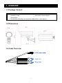
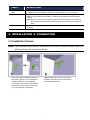
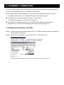
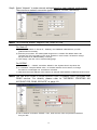
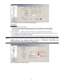
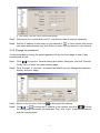
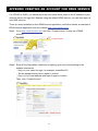
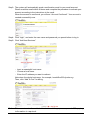
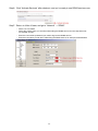
OUTDOOR IR NETWORK CAMERA Series INSTALLATION GUIDE Please read instructions thoroughly before operation and retain it for future reference. 1. OVERVIEW 1.1 Package Content □ □ □ □ Network camera □ Installation Sticker Installation Guide □ RJ45 cable extender adapter Ground Wire CD-ROM disc (including user manuals & CMS software “Video Viewer”) 1.2 Dimensions 1.2 Cable Overview 2 CABLE DESCRIPTION RJ45 network cable Connect it to the supplied RJ45 cable extender adapter for cable extension, and prepare another RJ45 network cable with suitable length for your connection. Reset wires Remove the insulating coating of these two wires, and twist them together to reset default. This will reset all parameters, including the IP address to factory default settings. Note: Disconnect power before twisting these two wires together, and connect to power again for reset default. When the reset is done, disconnect these two wires. Power wires Connect to AC power supply. For details, please refer to “2.2 Connect to power” at page 5. 2. INSTALLATION & CONNECTION 2.1 Install the Camera Note: The illustration below is for installation only, and the actual product may look different from the illustration below. Paste the supplied installation sticker to the location where your camera will be installed. Based on your installation environment, drill a hole in the middle of the sticker for the power & video cable to put through later if necessary. Slightly fasten the screws to (a) & (b) as indicated, and make sure the screws are not fastened to the end. 3 1) Based on your installation environment, put the power & cideo cable through the bracket, and determine the cabling of your camera: 3-1 – The cable walks along the wall 3-1 – The cable is hidden on the other side of the wall. 2) Hook the bracket with the camera to the screws fastened in step 2, and push it down to fix the bracket. 3) Secure the screws on (a) & (b), and fasten the other two screws to (c) & (d) to fix the bracket. Note: While securing the screws, it’s essential to connect the supplied ground wire (e) colored in yellow and green to the camera and earth for electric safety. Adjust the angles of the camera: (e) -- Adjust the vertical angle of the camera, and fix it with the screw & wrench supplied with the bracket. (f) -- Loosen the screw a little bit on the camera joint with the supplied wrench to adjust the horizontal angle of the camera, and fix it. 4 2.2 Connect to power Get a power cord and cut off its female connector side. Then, remove the insulating coating to reveal positive, negative and ground wires. Cut off the female connector and remove the coating to reveal positive, negative & ground wires. Find the two wires labeled “AC+” (red) & “AC-” (black) on your camera, and remove a small piece of their insulating coating to reveal the naked wires. Twist the camera’s and power cord’s wires together according to the corresponding electrodes (positive to positive, negative to negative, disregarding the ground wire). Then, use the insulation tape to cover the connected wires. 5 3. ETHERNET CONNECTION Before using this network camera, please follow the instructions below to finish the network connection settings based on your installation environment: To configure the network settings, you must connect the camera to your PC by LAN. For details, please refer to “3.1 Network Connection via LAN” at page 6. To configure the network settings via Wizard, please refer to “3.2 Network Configurations via Wizard” at page 10. To configure the network settings via our supplied CMS software, Video Viewer, please refer to “3.3 Network Configurations via Video Viewer” at page 14. 3.1 Network Connection via LAN Step1: Connect this network camera and your PC via a RJ45 network cable, and make sure the camera is powered on. Step2: Set the PC’s IP address as “192.168.1.XXX” (1~255, except 10). For Windows 2000 users: a) Select “Start” “Settings” “Network and Dial-up Connections”. b) Right-click on “Local Area Connection”, and select “Properties”. c) In the “General” tab, select “Internet Protocol (TCP/IP)”, and select “Properties”. 6 d) In the “General” tab, select “Use the following IP address”, and set the IP address as described below. Note: It’s recommended to note down the current settings first and then change as instructed. It’s helpful when you need to restore the PC network settings for connecting to Internet later. e) Click “OK” to close the “Internet Protocol (TCP/IP) Properties” dialog box. Then, click “Close” to close the “Local Area Connection Properties” dialog box. For Windows XP users: a) Select “start” “All Programs” “Control Panel” “Network and Internet Connections” “Network Connections” (If you’re in “Category View”). 7 b) In “LAN or High-Speed Internet”, right-click on “Local Area Connection”, and select “Properties”. c) In the “General” tab, select “Internet Protocol (TCP/IP)”, and select “Properties”. d) In the “General” tab, select “Use the following IP address”, and set the IP address to “192.168.1.XXX” (XXX can be any value from 1~255 except 10). Note: It’s recommended to note down the current settings first and then change as instructed. It’s helpful when you need to restore the PC network settings for connecting to Internet later. e) Click “OK” to close the “Internet Protocol (TCP/IP) Properties” dialog box. Then, click “Close” to close the “Local Area Connection Properties” dialog box. For Windows Vista users: a) Select “ ” (start) “Control Panel” “Network and Internet” to enter the “Network and Sharing Center”. Then, click “Manage network connections” (If you’re in “Category View”). b) Right-click on “Local Area Connection”, and select “Properties”. c) In the “General” tab, select “Internet Protocol Version 4 (TCP/IPv4)”, and select “Properties”. 8 d) In the “General” tab, select “Use the following IP address”, and set the IP address as described below. Note: It’s recommended to note down the current settings first and then change as instructed. It’s helpful when you need to restore the PC network settings for connecting to Internet later. e) Click “OK” to close the “Internet Protocol Version 4 (TCP/IPv4) Properties” dialog box. Then, click “Close” to close the “Local Area Connection Properties” dialog box. 9 3.2 Network Configurations via Wizard A quick installation wizard is available via your web browser for password change, date & time settings, and network configurations. For details about the wizard, please refer to “3.2.1 Setting in Wizard” at page 10. For details about DDNS setting for PPPoE and DHCP, please refer to “3.2.2 DDNS Setting” at page 12. Note: You can also change the settings in the system configuration page via your web browser later. For details, please refer to “5. ACCESSING THE CAMERA VIA WEB BROWSER” in the user manual. 3.2.1 Setting in Wizard Step1: Open your web browser, for example, Microsoft Internet Explorer, and enter “http://192.168.1.10” in the URL address box. Step2: In the login page, key in the default user name (admin) and password (admin), and enter the security code from the image below. Then, click “LOGIN”. Step3: The wizard is then starting analyzing your network environment, and shows your network environment. Select “Next” to continue. Step4: In “Account”, change the access password if needed. If not, leave all the columns blank, and select “Next”. 10 Step5: In “Date and Time”, check if the date and time setting are correct and modify if necessary. Step6: In “Network”, select the network type based on your network environment (Static IP / PPPoE / DHCP), and key in the information needed. Note: This camera doesn’t support POE router or hub. For Static IP: a) Enter the information of “Server IP”, “Gateway” and “Net Mask” obtained from your ISP (Internet Service Provider). b) Enter the port number. The valid number ranges from 1 to 9999. The default value is 80. Typically, the TCP port used by HTTP is 80. However in some cases, it is better to change this port number for added flexibility or security. For PPPOE: a) Enter the user name and password obtained from your ISP. b) Continue the DDNS setting as instructed in “3.2.2 DDNS Setting” when you’re prompted to restart the web browser in Step8. 11 For DHCP: a) Before selecting this option, you need to finish the DHCP router settings first. Get a router and connect it to the Internet via your PC (with Static IP or PPPoE setting). There are different setting methods for different routers. Please refer to their respective user manuals. b) Continue the DDNS setting as instructed in “3.2.2 DDNS Setting” when you’re prompted to restart the web browser in Step8. Step7: In “Apply”, all the changes are listed. Check if the changes are correct. ‧ If yes, click “Save”. ‧ If no, click “Back” to where the changes should be made for modification, and click “Save” to apply the settings. Note: You can also change the settings in the system configuration page via your web browser later. For details, please refer to “5. ACCESSING THE CAMERA VIA WEB BROWSER” in the user manual. Step8: You will be prompted to restart your web browser for network setting changes. ‧ For PPPoE and DHCP, continue as instructed in “3.2.2 DDNS Setting”. ‧ For Static IP, disconnect your camera and your PC, and connect them to Internet separately. Next, enter the IP address of the camera in the URL address box of the web browser, and see if you can access the camera successfully. 3.2.2 DDNS Setting Step1: Re-log in the network camera, and select “Close” for network environment checking. 12 Step2: In the live page, click “Configuration” to open the configuration page. Step3: Click “Network” “DDNS”, and check “DDNS Enable”. Step4: Select “default” in “System Name”. In “Hostname”, keep the default value, i.e. the MAC address of this camera, or change the name to a meaningful one. It’s easier to memorize. Then, note down the whole address of the camera, for example, MAC000E530D93E3.ddns.dvrtw.com.tw. Note: You can also create a DDNS account from a website which provides free DDNS service. For details, please refer to “APPENDIX CREATING AN ACCOUNT FOR DDNS SERVICE” at page 18. Step5: Click “Save” and log out. Then, disconnect your camera and your PC, and connect them to Internet separately. Step6: Enter the host name you just note down in the URL address box of the web browser, and see if you can access the camera successfully. 13 3.3 Network Configurations via Video Viewer 3.3.1 Install the software Step1: Place the supplied CD into your CD-ROM or DVD-ROM drive. The program will be automatically run. Step2: Click “Program” in the “Video Viewer” section to install Video Viewer, or click “Download The Latest Version” under “Program” to download the latest version of Video Viewer from the Internet (if your PC is connected to Internet). Step3: Follow the on-screen instructions to finish the installation. When the installation is completed, a shortcut icon “ ” will be placed on your PC desktop. Step3: Double-click “ ” on your PC desktop to open Video Viewer and enter the control panel. By defaults, the “Address Book” panel will be displayed on the right side of the control panel. Step4: Click “ ” “ ” to key in the default IP address, user name, password, and port number of the camera you intend to connect. The default values are as follows: Item IP address User name Password Port Default Value 192.168.1.10 admin admin 80 OR Click “ ”“ ” to search the available IP address(es) of other camera(s) under the same domain as your PC’s IP address. The found address(es) will be listed, ”. and can be added into the address book by clicking “ Step5: Double-click the IP address you just added into the address book to log in. 3.3.2 Network Setting Note: It’s recommended to have the qualified installer to plan and configure the network setting. Step1: Click “ ” to show the “General setting and utilities” dialog box, and click “Remote Config” twice to enter the camera setting page. 14 Step2: Select “Network” to make network settings based on your network environment. There are three network connection types: Static IP, PPPOE, and DHCP. Note: This camera doesn’t support POE router or hub. For Static IP: a) Enter the information of “Server IP”, “Gateway” and “NetMask” obtained from your ISP (Internet Service Provider). b) Enter the port number. The valid number ranges from 1 to 9999. The default value is 80. Typically, the TCP port used by HTTP is 80. However in some cases, it is better to change this port number for added flexibility or security. c) Click “Apply”, and click “OK” to exit the setting page. For PPPOE: a) Go to “Network” “DDNS”, and select “default” in the “System Name” drop-down list. b) In “Hostname”, keep the default value, i.e. the MAC address of this camera, or change the name to a meaningful one. It’s easier to memorize. c) Note down the whole address of the camera, for example, MAC000E53114389.ddns.dvrtw.com.tw. Note: You can also create a DDNS account from a website which provides free DDNS service. For details, please refer to “APPENDIX CREATING AN ACCOUNT FOR DDNS SERVICE” at page 18. d) Go to “Network” and select “PPPOE”. Then, enter the user name and password obtained from your ISP. 15 e) Click “Apply”, and click “OK” to exit the setting page. For DHCP: a) Finish the DHCP router setting. Get a router and connect it to the Internet via your PC (with Static IP or PPPoE setting). There are different setting methods for different routers. Please refer to their respective user manuals. b) Go to “Network” “DDNS”, and select “default” in the “System Name” drop-down list. c) In “Hostname”, keep the default value, i.e. the MAC address of this camera, or change the name to a meaningful one. It’s easier to memorize. d) Note down the whole address of the camera, for example, MAC000E53114389.ddns.dvrtw.com.tw. Note: You can also create a DDNS account from a website which provides free DDNS service. For details, please refer to “APPENDIX CREATING AN ACCOUNT FOR DDNS SERVICE” at page 18. e) Go to “Network” and select “DHCP”. 16 f) Click “Apply”, and click “OK” to exit the setting page. Step3: Disconnect your camera and your PC, and connect them to Internet separately. Step4: Add the IP address or host name of your camera in “ ” of Video Viewer with correct user name and password, and click it twice to see if you can access to your camera. 3.3.3 Change the password It’s recommended to change the default password for the first time usage in case of any unauthorized access. Step1: Click “ ” to show the “General setting and utilities” dialog box, and click “Remote Config” twice to enter the camera setting page. Step2: Click “General” “Account”, and select the default account. Change the password directly, and click “Apply”. Step3: Return to the live view, and click to disconnect the camera. “ “ ” to select the IP address of the camera, and click “ ” to enter Step4: Click the setting page and modify the password. Then, click “Login” to access the camera with the new password. 17 APPENDIX CREATING AN ACCOUNT FOR DDNS SERVICE For PPPOE or DHCP, you should enter the host name which points to the IP address of your network camera for login first. Besides using the default DDNS service, you can also apply for new DNS services. There are many websites for free DDNS service application, and below shows an example of DDNS account application from the website http://www.dyndns.com. Step1: Go to http://www.dyndns.com, and click “Create Account” to sign up a DDNS account. Step2: Enter all the information necessary for signing up an account according to the website instructions. ‧Key in a user name for login, for example, headoffice523. ‧Set the password and input it again to confirm. ‧Key in your E-mail address and input it again to confirm. Then, click “Create Account”. 18 Step3: The system will automatically send a confirmation email to your email account. Please read this email within 48 hours and complete the procedure to activate your account according to the instructions in the email. When the account is confirmed, you will see “Account Confirmed”. Your account is created successfully now. Step4: Click “login”, and enter the user name and password you preset before to log in. Step5: Click “Add Host Services”. ‧ Input a meaningful host name. ‧ Choose a host name. ‧ Enter the IP address you want to redirect. Note down the whole host name, for example, headoffice523.dyndns.org. Then, click “Add To Cart” for billing. Note: This service is free. Just finish the billing process, and NO paying information is required. 19 Step6: Click “Activate Services” after checkout, and you’re ready to use DDNS services now. Step7: Return to Video Viewer, and go to “Network” “DDNS”. ‧ Select “On” for DDNS. ‧ Select the system name you set when subscribing the DDNS service from the drop-down list, for example, dyndns. ‧ Enter the user name & password you used to log into the DDNS service. ‧ Enter the host name you set when subscribing the DDNS service, for example, headoffice523. 20