1
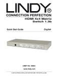
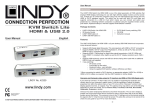
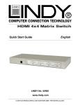
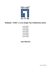
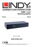
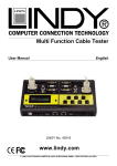
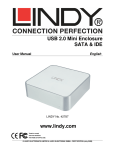
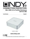
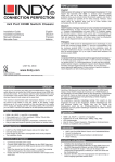
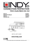
HDMI 8x8 Matrix
Switch 1.3c
Manual
English
LINDY No. 38047
www.lindy.com
© LINDY ELECTRONICS LIMITED & LINDY-ELEKTRONIK GMBH - Second Edition (November 2010)
1. Introduction
Thank you for purchasing the LINDY HDMI 8x8 Matrix Switch 1.3c with remote control
and RS232/USB support. This high performance switch offers you the maximum
convenience in HDMI signal distribution when you have multiple HDMI sources and
displays to connect together. Each of the eight HDMI inputs can be directed to any of
the eight HDMI outputs, so your displays can show up to eight different sources at the
same time. When the HDMI signal is progressed through the switch it is retimed and
level compensated, so that the output is a regenerated HDMI signal that can travel
another 10 metres. The switch can also be cascaded to multiple levels.
2. Features
•
•
•
•
•
•
•
•
•
•
HDMI 1.3c, HDCP 1.1 and DVI 1.0 compliant
HDMI input is compensated, clock/phase adjusted and jitter eliminated so the
output is a new standard HDMI signal
Supports high resolution input/output
Supports a wide range of PC and HDTV resolutions from VGA to UXGA and
480i to 1080p/60, 12 bit colour
Dip switches for EDID learning, audio/video settings & firmware update
3.5mm jack on the front allows you to extend the IR signal using the included IR
extension cable
HDCP compliant
Supports 7.1 channel surround sound or stereo digital audio
RS-232/USB control
IR remote control
3. Operation Control
Front Panel
1
1.
2.
3.
4.
5.
2
3
4
5
Power switch
Seven segment LED indicator
Input/Output indicators: Press the + or – switch on the input/output buttons to
select the source and display desired
IR receiver
IR extension jack
Rear Panel 6
2
1.
2.
3.
4.
5.
6.
7.
6
5
7
5
4
1
3
AC power input: 100-240V
RS-232 Communication port
USB control port
Main dip switches
HDMI dip switches
HDMI input ports
HDMI output ports
4. Remote Control
1.
2.
3.
4.
1
Power:
Turn the unit on/off
Source select:
Only buttons 1 & 2 are used in
this area. These are used in
conjunction with the “Fn” button
Input:
Press 1-8 to select the desired
input
Output:
Press 1-8 to select the desired
output
2
3
4
To use the remote control to switch channels, first select the input you require and
then select the output/outputs you would like it to display on. Repeat this for multiple
pictures on multiple screens. The channel switching takes approximately 2 seconds.
Fn + Source Sel 1 = Escape system lock
Fn + Source Sel 2 = System lock. The remote control becomes inactive except for the
above command.
5. Dip Switch Configuration
HDMI dip switches
Dip Switch Position
Pin #1
Pin #2
Video
Audio
Description
OFF (↑)
Up to
1080p
Surround
OFF (↑)
On (↓)
Up to
720p /
1080i
Stereo
On (↓)
OFF (↑)
Bypass
4
Bypass4
On (↓)
On (↓)
Bypass
Stereo
OFF (↑)
1
Default mode2 – Up to 1080p video
& surround sound audio output up to
7.1ch (DTS-HD & Dolby TrueHD)
Safe Mode3 – Force the system to
output at 720p/1080i video & stereo
audio for basic HDTV compatibility
EDID Learning Mode – for display
EDID Learning with the received
HDMI audio format
EDID Learning & Stereo Audio
Mode – for display EDID Learning
with stereo audio
1.
2.
3.
4.
If your HDTV displays video but no audio, set the audio mode to stereo
The factory default setting is both pins to off, this sets 1080p for video and
surround sound audio
For any other video/audio problems, turn Pin1 to “off” and Pin2 to “on”. This will
force the video signal to 720p and the audio signal to stereo
Bypass mode will maintain the original output format of video and audio. Setting
this mode may give you compatibility issues with the many different kinds of
sources and screens. If either the video or audio fail to work then try the different
dip switch settings above
Main dip switches
Dip Switch Position
Operation mode via RS-232 Port1
Operation mode via USB Port2
Block A
Firmware update
Block B
mode3
Block C
Pin #1
OFF (↑)
OFF (↑)
On (↓)
On (↓)
On (↓)
Pin#2
OFF (↑)
OFF (↑)
OFF (↑)
OFF (↑)
On (↓)
Pin#3
OFF (↑)
OFF (↑)
OFF (↑)
On (↓)
OFF (↑)
Pin#4
OFF (↑)
On (↓)
OFF (↑)
OFF (↑)
OFF (↑)
1.
Factory default setting, all pins set to “off”. This is the default mode for RS-232
control
2. For USB control, set Pins 1, 2 & 3 to “off” and Pin 4 to “on”
3. Firmware update mode can only be used via RS-232 with the PC set to COM1.
a. Power off your LINDY 8x8 HDMI Matrix and connect your serial cable to the
RS-232 port and serial port of your PC.
b. Execute the firmware update program on your PC via the COM 1 port
c. Set Pin 1 to the “on” position for firmware update mode
d. Set Pins 2 & 3 to the respective positions to assign which block is to be
updated
e. Power on your Matrix and the firmware update program should begin the
update sequence automatically. (If the program does not start, check the cable
connections)
f. Once the firmware update sequence has completed, the screen will display
“OK”, at this point turn off the Matrix
g. When all updates are complete, set the dip switches to normal operation mode
h. Power on the LINDY 8x8 HDMI Matrix
6. Software installation & control
Note: before inserting either the USB or serial cable, make sure that the main dip
switches are set to the correct position. Incorrect dip switch settings will result in the
HDMI Matrix not being picked up on the PC com port.
1.
2.
3.
4.
Plug either a USB A male to female cable or serial cable in to the back of the
Matrix and your computer.
For USB the computer will show that new hardware has been found. Click next
to continue and finish at the end.
When the hardware has fully installed, insert the CD provided.
Open the folder “01 control program\control program 8x8 HDMI matrix\8x8 HDMI
matrix setup” This will install the Matrix control software.
2
1
3
4
5
6
HDMI Input
mapping area
HDMI Output
mapping area
Status indicator
1.
Scan: Press the “scan” button, select “scan”, then select the detected port and
click OK
2.
Setting: Press the “setting” button then press the “get” button to read back the
device ID. Press the “set” button to write the device ID
3.
Linkage: Press the “linkage” button to read back all the status ID’s
4.
Open/Close: Press either the “open” or “close” button to open or close the COM
port
5.
Mapping:
Select All Output: Click on “Select All Output” then
select the source on the main menu. This quickly
sets all the outputs to the same source.
Unselect All Output: This releases all the outputs
Select Input 1~8 Output: Select the input source,
then select the output port icon.
Example: click on “Select Input 1 – Output”, then
select output port 1 & 2. The video and audio will
be sent to port 1 & 2.
6.
Fast Select:
Input Num – Output Num: This will set all input
Ports to its corresponding output port
ie. 1 to 2, 2 to 2
Input 1-8 – All Output: Quickly send the same
source to all outputs
7. Command Set
•
•
•
•
•
RS-232 Transmission format:
Baud rate:
9600 bps
Data length:
8 bits
Parity check:
None
Stop bit:
1 bit
Full details of the RS-232 protocols can be found on the CD provided:
D:\02 Documentation\01.Serial Command Set\8x8 Matrix_Command Set
Or
D:\02 Documentation\02.RS-232 Protocol Terminal\8x8 Matrix_ProtocolTerminal
CE Certification
This equipment complies with the requirements relating to electromagnetic compatibility, EN55022/EN55024 class B for
IEC/EN61000-4-2/3 the essential protection requirement of Council Directive 89/336/EEC on the approximation of the laws of
the Member States relating to electromagnetic compatibility.
FCC Certification
This equipment has been tested and found to comply with the limits for a Class B digital device, pursuant to part 15 of the FCC
Rules. These limits are designed to provide reasonable protection against harmful interference in a residential installation.
This equipment generates, uses, and can radiate radio frequency energy and, if not installed and used in accordance with the
instructions, may cause harmful interference to radio communications. However, there is no guarantee that interference will not
occur in a particular installation. If this equipment does cause harmful interference to radio or television reception, which can be
determined by turning the equipment off and on, the user is encouraged to try to correct the interference by one or more of the
following measures:
•
Reorient or relocate the receiving antenna
•
Increase the separation between the equipment and receiver
•
Connect the equipment into an outlet on a circuit different from that to which the receiver is connected
•
Consult the dealer or an experienced technician for help
You are cautioned that changes or modification not expressly approved by the party responsible for compliance could void your
authority to operate the equipment.
This device complies with part 15 of the FCC Rules.
Operation is subject to the following two conditions:
1.
This device may not cause harmful interference, and
2.
This device must accept any interference received, including interference that may cause undesired operation.
WEEE (Waste of Electrical and Electronic Equipment),
Recycling of Electronic Products
United Kingdom
In 2006 the European Union introduced regulations (WEEE) for the collection and recycling of all waste electrical and electronic
equipment. It is no longer allowable to simply throw away electrical and electronic equipment. Instead, these products must
enter the recycling process.
Each individual EU member state has implemented the WEEE regulations into national law in slightly different ways. Please
follow your national law when you want to dispose of any electrical or electronic products. More details can be obtained from
your national WEEE recycling agency.
Germany
Die Europäische Union hat mit der WEEE Direktive umfassende Regelungen für die Verschrottung und das Recycling von
Elektro- und Elektronikprodukten geschaffen. Diese wurden von der Bundesregierung im Elektro- und Elektronikgerätegesetz –
ElektroG in deutsches Recht umgesetzt. Dieses Gesetz verbietet vom 24.März 2006 an das Entsorgen von entsprechenden,
auch alten, Elektro- und Elektronikgeräten über die Hausmülltonne! Diese Geräte müssen den lokalen Sammelsystemen bzw.
örtlichen Sammelstellen zugeführt werden! Dort werden sie kostenlos entgegen genommen. Die Kosten für den weiteren
Recyclingprozess übernimmt die Gesamtheit der Gerätehersteller.
France
En 2006, l'union Européenne a introduit la nouvelle réglementation (DEEE) pour le recyclage de tout équipement électrique et
électronique.
Chaque Etat membre de l’ Union Européenne a mis en application la nouvelle réglementation DEEE de manières légèrement
différentes. Veuillez suivre le décret d’application correspondant à l’élimination des déchets électriques ou électroniques de
votre pays.
Italy
Nel 2006 l’unione europea ha introdotto regolamentazioni (WEEE) per la raccolta e il riciclo di apparecchi elettrici ed elettronici.
Non è più consentito semplicemente gettare queste apparecchiature, devono essere riciclate. Ogni stato membro dell’ EU ha
tramutato le direttive WEEE in leggi statali in varie misure. Fare riferimento alle leggi del proprio Stato quando si dispone di un
apparecchio elettrico o elettronico.
Per ulteriori dettagli fare riferimento alla direttiva WEEE sul riciclaggio del proprio Stato.
LINDY No. 38047
www.lindy.com