1
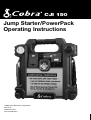
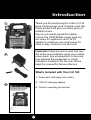
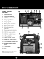
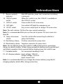
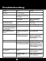
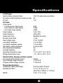
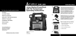
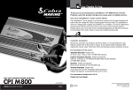
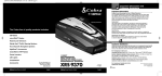
The Cobra line of quality products includes:
CB Radios
microTALK® Radios
Radar/Laser Detectors
Safety Alert® Traffic Warning Systems
HighGear® Accessories
CobraMarine® VHF Radios
Power Inverters
Accessories
For more information or to
order any of our products,
please visit our website:
www.cobra.com
Nothing Comes Close to Cobra®
CJI 150
Jump Starter/PowerPack
Operating Instructions
©2009 Cobra Electronics Corporation
Version D
Printed in China
Part No. 480-548-P
Introduction
1
Thank you for purchasing the Cobra CJI 150
jump starter/power pack. Properly used, this
Cobra product will give you many years of
reliable service.
Easy-to-use and designed for reliable
service, the 100W Mobile power pack can
run many AC appliances and 12V DC
appliance whenever you need power for
work or play, at home or on the road.
Important: Please be sure to read and save
the entire manual before using your mobile
power pack. Any misoperation or misusing
may damage the equipment or create
hazardous conditions for the user. Please
keep this manual for future reference.
2
What’s Included with Your CJI 150
1. Power pack with jump start cables
2. 120V AC charging adapter
3
3. Owner’s operating instructions
A1
Introduction
Buttons, Switches &
Indicatiors
9
10
8
6
7
1
2
1. USB power port
2. USB power indicator
3. USB/LED power switch
3
4. Charging indicator
4
5. Charging jack
6. Battery level indicators
7. Battery level button
8. Battery connection
indicator
11
5
12
9. Reverse polarity indicator
17
10. 120V AC power switch
14
11. 120V AC socket / cover
13
12. LED work lights
13. 12V DC socket / cover
14. Jump start power switch
15. Positive battery clamp (red)
16. Negative battery clamp
(black)
18
17. Carry handle
15
18. Fuse
Note: See page 6 - 7 for more
information on features.
A2
16
Introduction
Customer Assistance
Should you encounter any problems with this product, or not understand its
many features, please refer to this owner’s manual. If you require further
assistance after reading this manual, Cobra Electronics offers the following
customer assistance services:
For Assistance in the U.S.A.
Automated Help Desk English only.
24 hours a day, 7 days a week 773-889-3087 (phone).
Customer Assistance Operators English and Spanish.
8:00 a.m. to 5:30 p.m. Central Time, Monday through Friday
(except holidays) 773-889-3087 (phone).
Questions English and Spanish.
Faxes can be received at 773-622-2269 (fax).
Technical Assistance English only.
www.cobra.com (on-line: Frequently Asked Questions).
English and Spanish. [email protected] (e-mail).
For Assistance Outside the U.S.A.
Contact Your Local Dealer
©2009 Cobra Electronics Corporation
6500 West Cortland Street
Chicago, Illinois 60707 USA
www.cobra.com
A3
Notes
18
Contents
How to Use Your
Cobra CJI 150
Introduction...........................................................................................A1
Features of This Product
• 100W AC output for operating
household appliances
Our thanks to you
What’s included
Buttons, Switches & Indicators ..................................................A2
• 12 Volt DC power outlet for DC
accessories & appliances
Customer Assistance......................................................................A3
Conventions ........................................................................................2
• LED super bright emergency
light
Safety Information ............................................................................3
• 5V USB port to power up or
charge cellphones, PDAs or
consumer electronic devices
Controls and Indicators...................................................................6
Operation ..................................................................................................8
AC appliances......................................................................................8
• 500 peak Amps of instant
starting power to start vehicles
Some devices you can power up.................................................9
Operating AC appliances ................................................................9
• Rechargeable internal battery
Low battery shut down....................................................................9
• LED display indicates the
battery capacity
Overloads & high temperature protection ..............................9
High surge appliances......................................................................9
• Reverse polarity connection
indication & alarm
Problem appliances .......................................................................10
12V DC appliances ..........................................................................10
• On/off safety switch
Operating DC appliances..............................................................10
• Heavy duty cables and clamps
USB devices........................................................................................10
Jump starting a vehicle’s engine................................................11
Recharging the power pack battery.........................................12
Applications & Troubleshooting ...................................................13
Specifications .......................................................................................16
Product service ....................................................................................17
Warranty Information ....................................................................... 18
1
Introduction
Important: Please be sure to read and save the entire manual before using your
mobile power pack. Any misoperation or misusing may damage the equipment
or create hazardous conditions for the user. Please keep this manual for future
reference.
The following conventions are used in this manual:
WARNING Warnings identify conditions that could result in personal
injury or loss of life.
CAUTION
Cautions identify conditions or practices that could result
in damage to the unit or to other equipment.
NOTE: These notes describe an important action item or an item that you
must pay attention to.
Abbreviations and Acronyms:
A
Ampere
AC
Alternating Current
Ah
Amp-hours
DC
Direct Current
LED
light-emitting diode
mA
milli-Ampere
V
Volt
W
Watt
2
Introduction
Important Safety Instructions
WARNING: Charge unit fully prior to use.
Keep unit clear of fire and water. The 100W mobile power pack is not
intended for use in connection with life support systems or other medical
equipment or devices.
WARNING: Shock hazard.
Keep away from children. The power pack generates the same potentially
lethal AC power as a normal household wall outlet. Do not insert foreign
objects into the AC outlet, the DC power pack socket, the jump start cable
port, or the ventilation hole, do not expose this product to water, rain, snow,
condensation, or spray. Do not open the power pack. Have a qualified
technician perform any service work.
WARNING: Explosion hazard
Do not use this product where there are flammable fumes or gases, such as
in the bilge of a gasoline-powered boat, or near propane tanks. Do not use
this product in an enclosure containing automotive-type lead-acid batteries.
These batteries, unlike the sealed AGM battery in power pack, vent explosive
hydrogen gas which can be ignited by sparks from electrical connections.
When working on electrical equipment, always ensure someone is nearby to
help you in an emergency.
WARNING: Heated surface
Ensure at least 2” (5cm) air space is maintained on all sides of the power
pack. During operation, keep away from materials that may be affected by
high temperatures such as blankets, pillows and sleeping bags.
WARNING: Fire hazard
Never allow jump start cables’ red and black clamps to touch each other or
another common metal conductor. This could cause damage to the unit
and/or create a sparking/explosion hazard. Always disconnect the jump start
cables from the unit after use and clip the plastic guard over the jump start
cable port.
Jump start cable clamps must be connected positive to positive (red clamp
to battery “+”) and negative to negative (black clamp to battery “-“or engine
ground). A reverse polarity connection (positive to negative) may cause
damage to the unit and/or create a sparking/explosion hazard.
3
Introduction
WARNING: Fire hazard
The jump start feature is designed for short term operation only- less than 5
seconds. Operating the jump start feature for more than 5 seconds may
cause damage to the unit. Allow the power pack to cool down for at least 3
minutes after each jump start.
WARNING: Risk of explosion, fire or burns
The battery terminals exposed at the jump start cable port have enough
energy present to cause a spark, creating an explosion hazard, or to cause
burns if a metal object contacts both terminals. Always clip the plastic guard
over the port when not in use.
CAUTION: Equipment damage
Do not expose the power pack to temperatures over 104° F(40° C) or under
14° F(-10° C).
Precautions when working with batteries
WARNING: Explosion and fire hazard
1. Follow all instructions published by the battery manufacturer and the
manufacturer of the equipment in which the battery is installed.
2. Make sure the area around the battery is well-ventilated.
3. Never smoke or allow a spark or flame in vicinity of the engine or
batteries.
4. Be careful not to drop a metal object on the battery or allow a metal tool
to simultaneously touch the positive and negative cable ends or battery
terminals. It might spark or short-circuit the battery or other electrical
parts and cause an explosion.
5. Remove personal metal items such as rings, bracelets, necklaces, and
watches when working with batteries. Batteries produce a short-circuit
current high enough to weld a ring or other similar objects to metal,
causing a severe burn.
6. If you need to remove a battery, always remove the negative terminal
from the battery first. Make sure all accessories are off so you don’t cause
an arc.
4
Introduction
7. Someone should be within range of your voice, or close enough to come to
your aid when you work near batteries.
8. Have plenty of fresh water, soap and a supply of baking soda on hand in
the area of the batteries in case of contact with battery acid. Baking soda
neutralizes lead acid battery electrolyte.
9. The product is supplied with a rechargeable, sealed lead acid battery.
This battery is self contained and not easily replaceable. Batteries
must be disposed of properly when they no longer hold a charge.
Proper charging practices will increase the life of the batteries.
For information on battery recycling call toll free 800-822-8837.
5
Introduction
Controls and Indicators:
1. USB power port
Provides 5 volts output for consumer
electronics devices.
2. USB power indicator
Illuminates when USB port is in use.
3. USB/LED power switch If the switch is flipped left, the USB port can
provide power. Flipped right, the white LED lamps
illuminate. Center position, the USB port and LED
lamps are off.
4. Charging indicator
2-color LED indicator. When the battery is being
charged, this LED indicator lights red, when the
battery is fully charged, the LED indicator lights
green.
5. Charging jack
Charge the battery in the unit by inserting the
connector from the AC charging adapter into this jack.
6. Battery level indicators:
Battery Value
Display Mode
U<12.2V
Only red LED indicator lights.
12.2V<U<12.4V
Red and yellow LED light.
12.4V<U<12.6V
Red, yellow and one green LED light.
U>12.6V
Red, yellow and two green LED all light.
Note: It is recommended that you should check the battery voltage every 30
minutes during charging.
7. Battery level button When pressed, indicates the battery charge level.
8.
Battery connection
indicator
Green LED indicates connection to a battery
is correct.
6
Introduction
9.
Reverse polarity
indicator
Red LED indicates jump start connection to battery
is incorrect.
10. 120V AC power
switch
When this switch is on, the 120V AC is available at
the 120V AC socket.
11. 120V AC socket
Power outlet for AC accessories.
12. LED lights
Four white LED lights for emergency use.
13. 12V DC socket
Easy-access output port to charge 12V accessories.
Note: The unit contains 15A fuse for over current protection.
Note: It is recommended that you use the unit to power 12V accessories less
than 8A.
14. Jump start power
switch
Turn this switch after connecting to vehicle to
jump start battery.
15. Red battery clamp
Positive connector for jump starts.
16. Black battery clamp
Negative connector for jump starts.
Note: Be sure that the jump start switch is in off position prior to connecting
clamps to vehicle’s battery. Attach clamps properly to battery (red to positive post,
and black to negative chassis ground) before turning jump start switch to on.
17. Portable handle
For convenient handling of unit.
18. AC charging adapter: Input voltage: 120V AC
Output voltage: 13.5V DC
Input current: 0.3A
Note: It is recommended that you charge the interior battery using the AC
charging adapter, which offers charge protection.
7
Operation
CAUTION: Read all operating instructions before operating the power pack.
The power pack is not intended for use as a UPS (Uninterruptible Power
Supply). The unit should be operated only in locations that meet the
following requirements:
Dry
Don’t allow water or other liquids to drop or splash on the unit.
Cool
Ambient air temperature should be between -10° and 40° C
(14° and 104° F) – the cooler the better within this range.
Ventilated
Leave at least 2” (5 cm) clearance around the unit for air flow.
Ensure that the ventilation openings are not obstructed.
Safe
Do not operate the unit in the same compartment as batteries
or in any compartment capable of storing flammable liquids
like gasoline.
Protect from Do not operate the unit where it will be exposed to battery
battery gases gases. These gases are very corrosive and prolonged exposure
will damage the power pack
AC appliances
The power pack has one grounded AC power outlet for use with AC
appliance. You can either plug the appliance directly into the AC outlet or you
can use an AC power bar to increase the number of outlets available.
However, for continuous operations, the combined loads must be less than
80W. The less wattage used, the longer the power pack will operate before
recharging is required.
Operating range:
• 80 watts or less for continuous operation
• 100 watts for 5-minute operation
Some appliance may be difficult or impossible to operate from the power
pack. They may have high surge requirements or may be incompatible with
the output waveform of the power pack. See “High Surge Appliances” and
“Trouble Appliances” (page 10).
NOTE: To determine required wattage for a device, look up required Amps a
device is rated. This Amperage is found on device I.D. tag in back of the unit.
Multiply Amps X Volts = Watts.
8
Operation
Some devices you can power up:
• 13” TV
(80W)
• Video Game System (20W)
• Weather Radio
(10W)
Operating AC appliances
1. Check battery status to ensure the battery is fully charged.
2. Open the AC Outlet cover.
3. Turn the AC socket switch ON.
4. Plug the AC appliance into AC outlets.
5. Turn the AC appliance ON.
6. Recharge the power pack immediately after use. See “recharging the
power pack battery” (page 12).
Low battery shut down
Unit will automatically shutdown when the battery reaches 10.0V DC. You must
turn off the AC power switch and charge the battery.
Overload and high temperature protection
In the event of an overload (>100W) or overheating, the power pack
automatically shuts down power to the AC outlets. If, after a while the audible
warning is ignored and a manual reset is not performed, the unit will do a
complete shutdown automatically.
High surge appliances
The wattage rating of AC appliance is the average power used by the appliance.
Appliances such as televisions, computer monitors and appliances with motors
consume much more power than their average rating when they are first
switched on.
Although power pack can supply momentary surge power up to 400W, some
appliances may exceed the capabilities of the power pack and trigger the
inverter’s safety overload shutdown circuit.
9
Operation
Problem appliances
The output of the power pack inverter is non-sinusoidal. Some equipment may
be damaged by the inverter’s modified sine wave output (non-sinusoidal).
Some appliance, including the types listed below, may be damaged if they are
connected to the inverter.
• Electronics that modulate RF (radio frequency) signals on the AC line will not
work and may be damaged.
• Speed controllers found in some fans, power tools, kitchen appliance, and
other loads may be damaged.
• Some chargers for small rechargeable batteries can be damaged.
• Metal halide arc (MHI) lights can be damaged.
Note: If you are unsure about powering any device with the power pack,
contact the manufacturer of the device to determine whether it is compatible
with the modified sine wave output.
12V DC appliances
The power pack can operate one 12V DC auto, RV, marine, or other portable DC
appliance that draws 10 amps or less from its DC socket. The combined load
must not exceed 120 W, The less combined wattage used, the longer the power
pack will operate before recharging is required.
Operating DC appliances:
1. Check battery status to ensure the battery is fully charged.
2. Open the DC socket.
3. Plug the DC appliance into the DC socket.
4. Turn the DC appliance ON.
5. Recharge the power pack immediately after use.
USB Devices
The power pack can charge or power one USB-chargeable device through its
USB port. Compatible devices include most MP3 players, PDAs, digital cameras,
and camcorders that have internal batteries which can be charged via the USB
port of a desktop/laptop computer.
USB-chargeable devices usually include a special USB cable (not supplied) that
attaches one end to the USB port and the other end to the device.
10
Operation
Jump starting a vehicle’s engine
You can use the power pack to jump start a vehicle (or boat engine) that has
a 12V starting battery using the jump start cables supplied with the unit.
WARNING: Fire Hazard
A reverse polarity connection may cause damage to the unit and/or create a
sparking/explosion hazard. Never allow cables’ red and black clamps to touch
each other or another common metal conductor. The connection of the
cables to the vehicle’s battery terminals must be positive to positive (red
clamp to battery “+”) and negative to negative (black clamp to battery “-“ or
vehicle chassis).
NOTE: Carefully follow these instructions for jump starting your vehicle as
they may be different from the instructions supplied with other jump start
products or cables.
To jump start a vehicle:
1. Turn off the vehicle and all accessories.
2. Place the unit on a flat and stable surface near the battery which need to be
boosted. Ensure that the unit’s jump start power switch is “OFF”.
3. Connect the red positive (+) clamp of the cables to the positive (+)
terminal of the engine battery.
4. Connect the black negative (-) clamp of the cables to the engine block,
cylinder head, or other stationary heavy metal part of the motor. If the red
“Reverse Polarity” LED illuminates, then reverse polarity has been detected.
Correct polarity must be established before proceeding. Disconnect the
jump starting clamps from the vehicle’s battery and repeat steps (3) and (4).
5. Switch on the jump start power switch. Before starting the engine, make
sure the jumpstarter pack and the cables are clear of the metal parts and
other moving things.
6. Crank the engine for 5 seconds or until it starts, whichever is first.
WARNING: Fire hazard
Do not try to start the engine for more than 5 seconds. The jump start
feature is designed for short term operation only. Operating the jump
starting feature for more than 5 seconds may cause damage to the unit.
Allow the unit to cool down for at least 3 minutes after each start attempt.
11
Operation
To jump start a vehicle continued:
7. Switch off the jump start power switch.
8. Remove the red positive (+) clamp and then the black negative (-) clamp.
Recharging the power pack battery
CAUTION: Do not operate AC or DC appliance while the power pack is
being charged.
Charging with the AC charging adapter
Using the AC charging adapter is the simplest method for recharging the
battery. While charging from an AC source, the charging status LED indicator
will light red. When the battery has reached capacity, the indicator will light
green. Charging when the battery is fully discharged takes around 23 hours.
NOTE: Recharge the 100W mobile power pack as soon as possible after each
use. When not used the power pack, it should be recharged every 3 months!
To recharge with AC charger:
1. Turn the rotary switch to the “OFF” position.
2. Plug AC charging adapter into charging jack on the front of the unit.
3. Plug AC charging adapter into 120V AC electrical outlet.
4. Continually charge until the battery is fully charged; for about 23 hours.
CAUTION: The 23-hour charging time for the unit assumes that there is 120V
at the AC wall outlet. If the voltage is less than 120V AC, it may take more
than 23 hours to fully recharging. Once fully charged, the charging current
automatically reduces to a floating charge mode, and the unit may be left
permanently connected to the AC charger.
12
Applications &
Troubleshooting
Applications
AC Appliance
Watts Required
Cordless Phone (Stand-by)
5
Weather Radio
8
Portable Stereo
10
Florescent Work Light
14
Fan
20
Laptop Computer
25
Incandescent Lamp Work Light
40
13" Color Television
60
DC Appliance
Watts Required
Cellular Phone
6
Portable CD Player
10
Portable Cooler
30
Hours*
16
10
7
4
4
3
1.5
1.25
Hours*
14
9
3
* All run times are estimates
Troubleshooting
Buzzing in audio systems and radios
Some inexpensive stereo systems and AM-FM radios have inadequate internal
power supply filtering and “buzz” slightly when powered by the power pack.
Generally, the only solution is an audio product with a higher quality filter.
Television interference
The power pack is shielded to minimize its interference with TV signals.
However, with weak TV signals interference may be visible in the form of lines
scrolling across the screen. The following should minimize or eliminate the
problem:
• Increase the distance between the inverter and the TV, antenna and cables.
• Adjust the orientation of the inverter television, antenna and cables.
• Maximize TV signal strength by using a better antenna and use shielded
antenna cable where possible.
WARNING: Electric shock hazard
Do not remove the cover of the unit or disassemble. The unit does not contain
any internal user-serviceable parts and attempting to service the unit yourself
could result in electrical shock or burn.
13
Troubleshooting
Problem
Cause
Solution
The power pack can not jump
start vehicle
The battery in the power pack Charge it for at 23 hours
is not fully charged
The engine start capacity
exceeds the power pack jump
start capacity.
The charging status LED
indicator does not light.
The charging status LED
indicator still lights red and has
not charged to steady after 50
hours of charging.
The AC appliance does not
operate; audible alarm is not
sounding.
Run time for appliance is less
than expected.
The power pack’s battery has Replace the power pack’s
been damaged
battery (consult service
technician).
No AC power at the AC wall
Ensure power is available at the
outlet.
AC wall outlet.
AC charging adapter is faulty. Replace 120V AC charger
The AC charger’s output is too Replace the AC charger
low.
AC appliance rated more than Use AC appliance with a power
80W, the safety overload has rating less than 80W.
tripped.
AC appliance rated less than
80W, high starting surge has
tripped the safety overload.
AC appliance may exceed the
power pack’s surge capability.
Use an AC appliance with a
starting surge within the power
pack surge rating.
Battery has discharged to 10V
Inverter has overheated due to
poor ventilation or excessively
warm environmental condition.
Recharge the battery.
Allow the power pack to cool for
15 minutes or more. Clear
blocked fan opening or remove
objects covering the unit, then
restart the power pack. Move to
a cooler environment.
Internal battery is not fully
charged,
Recharge using the AC charger,
until the charging status LED
indicator light green.
AC appliance power
consumption is higher than
expected.
Check AC appliance power or
wattage rating (or current draw
for 12V DC appliance).
14
Specifications
12 DC Power:
Internal battery (Capacity/Type)
DC power socket (maximum continuous load)
DC fuse
7Ah/12V sealed lead-acid battery
8A
15A
AC Power:
Output power
• Continuous AC output power
• Five minute AC output power
• AC output surge capacity
Output voltage
Output frequency
Output wave form
No load current draw
Input voltage range
Low battery shutdown
Low battery shutdown resume
High battery voltage shutdown
Over temperature shutdown
Overload shutdown
Operating temperature range
Storage temperature range
80W
100W
400W
104V-125V
58Hz-62Hz
Modified sine wave
<0.5A
10.5V-15.5VDC
10.0±0.3VDC
12.0±0.3VDC
15.5V±0.3VDC
Yes
Yes
14°F~104°F (-10°C~40°C)
-4°F~158°F (-20°C~70°C)
Internal battery charging controller system:
AC charging bulk charging current
300mA
Peak charging voltage (nominal)
14.2V±0.2V
Charging restart voltage (nominal)
12.9V±0.2V
Physical Specifications:
Jumpstarter cables (size/length)
Dimensions H*W*D
Weight
8.37mm2/(460±19.5)mm
13” H x 12” W x 4.5” D
(330.2mm x 309mm x 114.3mm)
9 lbs., 3.7 oz. (4.3g)
15
Product Service
For any questions about operating this new Cobra product, or if parts are
missing…PLEASE CALL COBRA FIRST…do not return this product to the store.
See customer assistance on page A3.
If your product should require factory service, please call Cobra first before
sending your unit. This will ensure the fastest turn-around time on your repair.
You may be asked to send your jumpstarter/power pack to the Cobra factory.
It will be necessary to furnish the following to have the product serviced and
returned.
1. For warranty repair include some form of proof-of-purchase, such as a
mechanical reproduction or carbon copy of a sales receipt. If you send the
original receipt, it cannot be returned.
2. Send the entire product.
3. Enclose a description of what is happening with the jump starter/power
pack. Include a typed or clearly printed name and address of where the unit
is to be returned.
4. Pack unit securely to prevent damage in transit. If possible, use the original
packing material.
5. Ship prepaid and insured by way of a traceable carrier such as United Parcel
Service (UPS) or Priority Mail to avoid loss in transit to:
Cobra Factory Service
Cobra Electronics Corporation
6500 West Cortland Street
Chicago, Illinois 60707 USA.
6. If the jumpstarter/power pack is in warranty, upon receipt of your unit, it
will either be repaired or exchanged depending on the model. Please allow
approximately three to four weeks before contacting Cobra for status. If the
unit is out of warranty, a letter will automatically be sent informing you of
the repair charge or replacement charge.
If you have any questions, please call 773-889-3087 for assistance.
16
Warranty and Trademark
Acknowledgement
For Products Purchased in the U.S.A.
Cobra Electronics Corporation warrants that its Cobra jump starter/power pack,
and the component parts thereof, will be free of defects in workmanship and
materials for a period of one year from the date of first consumer purchase. This
warranty may be enforced by the first consumer purchaser, provided that the
product is utilized within the U.S.A.
Cobra will, without charge, repair or replace, at its option, defective jump
starter/power pack products or component parts upon delivery to the Cobra
Factory Service department, accompanied by proof of the date of first
consumer purchase, such as a duplicated copy of a sales receipt.
You must pay any initial shipping charges required to ship the product for
warranty service, but the return charges will be at Cobra’s expense, if the product
is repaired or replaced under warranty. This warranty gives you specific legal
rights, and you may also have other rights which may vary from state to state.
Exclusions: This limited warranty does not apply:
1. To any product damaged by accident.
2. In the event of misuse or abuse of the product or as a result of unauthorized
alterations or repairs.
3. If the serial number has been altered, defaced, or removed.
4. If the owner of the product resides outside the U.S.A.
All implied warranties, including warranties of merchantability and fitness for a
particular purpose are limited in duration to the length of this warranty. Cobra
shall not be liable for any incidental, consequential or other damages; including,
without limitation, to damages resulting from loss of use or cost of installation.
Some states do not allow limitations on how long an implied warranty lasts
and/or do not allow the exclusion or limitation of incidental or consequential
damages, so the above limitations may not apply to you.
For Products Purchased Outside the U.S.A.
Please contact your local dealer for warranty information.
Trademark Acknowledgement
Cobra®, Nothing Comes Close to a Cobra® and the snake design are registered
trademarks of Cobra Electronics Corporation, USA.
Cobra Electronics Corporation™ is a trademark of Cobra Electronics
Corporation, USA.
17