1
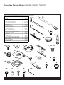
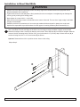
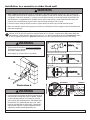
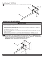
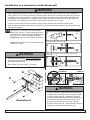
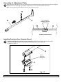
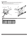
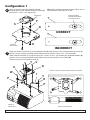
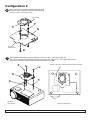
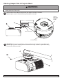
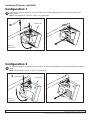
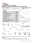
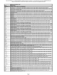
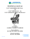
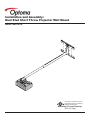
Installation and Assembly:
Dual Stud Short Throw Projector Wall Mount
Model: BM-3001N
This product is intended for use with UL
Listed products and must be installed by a
qualified professional installer.
Maximum UL Load Capacity:
35 lb (15.8 kg)
Visit the Peerless Web Site at www.peerlessmounts.com
ISSUED: 11-18-10 SHEET #: 125-9159-1
Note: Read entire instruction sheet before you start installation and assembly.
WARNING
• Do not begin to install your Peerless product until you have read and understood the instructions and warnings
contained in this Installation Sheet. If you have any questions regarding any of the instructions or warnings, please
call Peerless customer care at 1-800-865-2112.
• This product should only be installed by someone of good mechanical aptitude, has experience with basic building
construction, and fully understands these instructions.
• Make sure that the supporting surface will safely support the combined load of the equipment and all attached hardware and components.
• Never exceed the Maximum UL Load Capacity. See page 1.
• If mounting to wood studs, make sure that mounting screws are anchored into the center of the studs. Use of an
“edge to edge” stud finder is highly recommended.
• Always use an assistant or mechanical lifting equipment to safely lift and position equipment.
• Tighten screws firmly, but do not overtighten. Overtightening can damage the items, greatly reducing their holding
power.
• This product is intended for indoor use only. Use of this product outdoors could lead to product failure and personal
injury.
• This product was designed and intended to be mounted to the following supporting surfaces checked below with
the hardware included in this product as specified in the installation sheet. To mount this product to an alternative
supporting surface, contact Peerless customer care at 1 800 865-2112.
• This product was designed to be installed on the following wall construction only;
WALL CONSTRUCTION
ADDITIONAL HARDWARE REQUIRED
x
x
x
Wood Stud
Solid Concrete Cinder Block Metal Stud
Brick Other or unsure?
None
None
None
Contact Customer Service (Not Evaluated By UL)
Contact Customer Service (Not Evaluated By UL)
Contact Customer Service
Tools Needed for Assembly
• stud finder (“edge to edge” stud finder recommended)
• level
• drill
• 5/32” bit (wood installation)
• 1/4” bit (concrete/cinder block installation)
• phillips screwdriver
Accessories
• WSP320
(required for installation to metal studs) (Not Evaluated by UL)
• ACC-MIS550
(required for installation to metal studs) (Not Evaluated by UL)
• ACC020 Projector Security Cable (Not Evaluated by UL)
• WBK100
(wall plate accessory kit ) (Not Evaluated by UL)
Table of Contents
Parts List.................................................................................................................................................................................3
Installation to Wood ................................................................................................................................................................4
Installation to Concrete/Cinder Block .....................................................................................................................................5
Assembly of Adjustment Tube ................................................................................................................................................8
Installing Projector Mount .......................................................................................................................................................8
Routing Cables........................................................................................................................................................................9
Visit the Peerless Web Site at www.peerlessmounts.com
2 of 13
ISSUED: 11-18-10 SHEET #: 125-9159-1
Compatible Projector Models: EX525ST, TX610ST, TW610ST Before you start check the parts list to insure all of the parts shown are included.
Parts List
A
B
C
D
E
F
G
H
I
J
K
L
M
N
O
P
Q
R
S
T
U
V
W
X
Y
Z
AA
Description
wall arm
adjustment tube
4 mm allen wrench
M5x10mmserratedsocketpinscrew
#14-x2.5phillipsheadwoodscrew
tube cap
concrete anchor
1/4"-20 socket pin screw
1/4"-20 flat washer
precision gear projector mount
wall plate
5/16-18x1/2carriagebolt
5/16 - 18 serrated flanged lock nut
adapter plate
10-32x3/8"socketpinserratedwasherheadscrew
.219IDx.5ODx.125spacer
10-32x1/4"socketpinwithlockpatch
#8 flat washer
connection block
extensionbracket
M3x12mmsocketpinserratedwasherheadscrew
M4x8mmsocketpinserratedwasherheadscrew
M4x12mmknob
.198x.313x.375spacers
M4x16mmscrew
M3x20mmknob
2 mm allen wrench
Qty.
1
1
1
2
4
1
4
2
2
1
1
4
4
1
2
6
1
8
1
4
4
4
2
1
4
1
1
Part #
055-1912
055-1911
560-9646
510-1126
5S1-015-C03
590-1263
590-0320
520-1054
540-1078
055-KPRGU-B-3
055-1923
520-9207
530-1016
XXX-XXXX
520-1151
540-1032
520-1196
540-1001
580-1065
055-1940
510-1003
510-1005
560-1154
590-2020
510-1087
560-1149
560-1097
A
B
C
D
E
G
F
NOTE: Some parts may appear slightly different than illustrated.
H
I
K
J
N
M
O
R
W
L
P
S
X
T
Y
Z
Q
U
V
AA
3 of 13
ISSUED: 11-18-10 SHEET #: 125-9159-1
Installation to Wood Stud Walls
WARNING
• Installer must verify that the supporting surface will safely support the combined load of the equipment and all
attached hardware and components.
• Tighten wood screws so that wall plate is firmly attached, but do not overtighten. Overtightening can damage the
screws, greatly reducing their holding power.
• Never tighten in excess of 80 in. • lb (9 N.M.).
• Make sure that mounting screws are anchored into the center of the stud. The use of an “edge to edge” stud finder
is highly recommended.
• Hardware provided is for attachment of mount through standard thickness drywall or plaster into wood studs.
Installers are responsible to provide hardware for other types of mounting situations (Not Evaluated By UL).
Note: For mounting using wall plate (K), refer to page 6.
Use a stud finder to locate the edges of the stud. Use of an edge-to-edge stud finder is highly recommended.
1 Based on its edges, draw a vertical line down the stud’s center. Place wall arm (A) on wall as a template. Mark the
center of the four mounting holes. Drill four 5/32” (4 mm) dia. holes 2-1/2” (65 mm) deep. Secure wall arm (A) to
wood stud using four #14 x 2-1/2” wood screws (E) as shown.
Optional: Rotate wall arm 180° to position the arm closer to the ceiling.
Skip to Step 2.
E
A
Visit the Peerless Web Site at www.peerlessmounts.com
4 of 13
ISSUED: 11-18-10 SHEET #: 125-9159-1
Installation to a concrete or cinder block wall
WARNING
• When installing Peerless wall mounts on cinder block, verify that you have a minimum of 1-3/8” of actual concrete surface in the hole to be used for the concrete anchors. Do not drill into mortar joints! Be sure to mount in
a solid part of the block, generally 1” minimum from the side of the block. Cinder block must meet ASTM C-90
specifications. It is suggested that a standard electric drill on slow setting is used to drill the hole instead of a
hammer drill to avoid breaking out the back of the hole when entering a void or cavity.
• Concrete must be 2000 psi density minimum. Lighter density concrete may not hold concrete anchor.
• Make sure that the wall will safely support four times the combined load of the equipment and all attached hardware and components.
Note: For mounting using wall plate (K), refer to page 6.
Drill four 5/16” (8 mm) dia. holes to a minimum depth of 2.5” (64 mm). Insert anchors (G) in holes flush with
1 wall as shown. Attach wall arm (A) using four #14 x 2 -1/2” wood screws (E) as shown in Illustration A and 1,
2, and 3. Tighten all fasteners. Optional: Rotate wall arm 180° to position the arm closer to the ceiling.
WARNING
• Tighten wood screws firmly, but do not overtighten.
Overtightening can damage the screws, greatly reducing their holding power.
• Never tighten in excess of 80 in • lb (9 N.M.).
concrete
surface
1
G
Drill holes and insert anchors (G).
A
2
E
G
G
Place wall arm (A) over anchors (G) and secure with
screws (E).
3
E
E
G
Tighten
allfasteners.
fasteners.
Tighten all
Illustration A
WARNING
• Concrete anchors are not intended for attachment to
concrete wall covered with a layer of plaster, drywall,
or other finishing material. If mounting to concrete
wall covered with plaster/drywall is unavoidable (Not
Evaluated By UL), plaster/drywall (up to 5/8” thick)
must be counterbored as shown right. If plaster/drywall is thicker than 5/8”, custom fasteners must be
supplied by installer (Not Evaluated By UL).
Visit the Peerless Web Site at www.peerlessmounts.com
INCORRECT
INCORRECT
CUTAWAY
CUTAWAYVIEW
VIEW
A
5 of 13
concrete
concrete
wall
wall
plate
plate
plaster/
dry wall
CORRECT
CORRECT
concrete
concrete
wall
wall
plate
plate
plaster/
plaster/
drywall
wall
dry
ISSUED: 11-18-10 SHEET #: 125-9159-1
Installation to Wall Plate
1
Secure wall arm (A) to wall plate (K) using four carriage bolts (L) and lock nuts (M).
L
M
A
K
Installation to Wood Stud Walls
WARNING
• Installer must verify that the supporting surface will safely support the combined load of the equipment and all
attached hardware and components.
• Tighten wood screws so that wall plate is firmly attached, but do not overtighten. Overtightening can damage the
screws, greatly reducing their holding power.
• Never tighten in excess of 80 in. • lb (9 N.M.).
• Make sure that mounting screws are anchored into the center of the stud. The use of an “edge to edge” stud finder
is highly recommended.
• Hardware provided is for attachment of mount through standard thickness drywall or plaster into wood studs.
Installers are responsible to provide hardware for other types of mounting situations. (Not Evaluated By UL)
1-1
Use a stud finder to locate the edges of the stud. Use of an edge-to-edge stud finder is highly recommended.
Based on its edges, draw a vertical line down the stud’s center. Place wall plate (K) on wall as a template. Mark
the center of the four mounting holes. Drill four 5/32” (4 mm) dia. holes 2-1/2” (65 mm) deep. Secure wall plate (K)
to wood stud using four #14 x 2-1/2” wood screws (E) as shown. Skip to Step 2.
Optional: Rotate wall arm 180° to position the arm closer to the ceiling.
E
6 of 13
Visit the Peerless Web Site at www.peerlessmounts.com
K
ISSUED: 11-18-10 SHEET #: 125-9159-1
Installation to a concrete or cinder block wall
WARNING
• When installing Peerless wall mounts on cinder block, verify that you have a minimum of 1-3/8” of actual concrete surface in the hole to be used for the concrete anchors. Do not drill into mortar joints! Be sure to mount in
a solid part of the block, generally 1” minimum from the side of the block. Cinder block must meet ASTM C-90
specifications. It is suggested that a standard electric drill on slow setting is used to drill the hole instead of a
hammer drill to avoid breaking out the back of the hole when entering a void or cavity.
• Concrete must be 2000 psi density minimum. Lighter density concrete may not hold concrete anchor.
• Make sure that the wall will safely support four times the combined load of the equipment and all attached hardware and components.
1-2 Drill four 5/16” (8 mm) dia. holes to a minimum
depth of 2.5” (64 mm). Insert anchors (G) in holes
flush with wall as shown. Attach wall plate (K) using
four #14 x 2 -1/2” wood screws (E) as shown in
Illustration A and 1, 2, and 3. Tighten all fasteners.
Optional: Rotate wall arm 180° to position the arm
closer to the ceiling.
WARNING
concrete
surface
1
G
Drill holes and insert anchors (G).
K
2
E
G
Place wall plate (K) over anchors (G) and secure with
screws (E).
3
• Tighten wood screws firmly, but do not overtighten.
Overtightening can damage the screws, greatly reducing their holding power.
E
• Never tighten in excess of 80 in • lb (9 N.M.).
G
Tighten
allfasteners.
fasteners.
Tighten all
CUTAWAYVIEW
VIEW
CUTAWAY
G
E
K
Illustration A
concrete
concrete
wall
wall
plate
plate
plaster/
plaster/
dry
wall
dry wall
CORRECT
CORRECT
concrete
concrete
wall
wall
plate
plate
plaster/
plaster/
dry
wall
dry wall
WARNING
• Concrete anchors are not intended for attachment to
concrete wall covered with a layer of plaster, drywall,
or other finishing material. If mounting to concrete
wall covered with plaster/drywall is unavoidable (Not
Evaluated By UL), plaster/drywall (up to 5/8” thick)
must be counter bored as shown right. If plaster/
drywall is thicker than 5/8”, custom fasteners must be
supplied by installer (Not Evaluated By UL).
7 of 13
Visit the Peerless Web Site at www.peerlessmounts.com
INCORRECT
INCORRECT
ISSUED: 11-18-10 SHEET #: 125-9159-1
Assembly of Adjustment Tube
2
Slide adjustment tube (B) into wall arm (A) and adjust to the desired projector throw distance as shown. Using two
separate slots on wall arm (A), lock position using two M5 x 10 mm screws (D) as shown below.
Note: Securing adjustment tube (B) into wall arm (A) requires two slots. D
B
A
TWO SCREWS (D)
REQUIRED THROUGH
TWO SLOTS
B
A
MAXIMUM EXTENSION SHOWN
Installing Precision Gear Projector Mount
3
Installing PRG projector mount to wall arm assembly: Attach precision gear projector mount (J) to
adjustment tube (B) using two 1/4-20 socket pin screws (H) and two flat washers (I)
as shown in Figure 3.1.
B
ARROW
INDICATES
FRONT OF
PROJECTOR
J
I
H
Visit the Peerless Web Site at www.peerlessmounts.com
8 of 13
fig. 3.1
ISSUED: 11-18-10 SHEET #: 125-9159-1
Routing Cables
Routing Cables through precision gear projector mount (J) and wall arm assembly: Guide
projector cables into openings in projector mount and wall arm assembly as shown below.
Insert tube cap (F) into end of adjustment tube (B).
Note: Cables must be removed from projector before routing through wall arm.
4
PROJECTOR CABLES
B
A
PROJECTOR CABLES
F
J
5
Check your projector for the corresponding configuration and page.
Model EX525ST
TW610ST
TX610ST
Configuration
1
2
2
Visit the Peerless Web Site at www.peerlessmounts.com
Page
10
11
11
9 of 13
ISSUED: 11-18-10 SHEET #: 125-9159-1
Configuration 1
Attach connection block (S) to adapter plate (N)
using two #10-32 x 3/8" serrated socket pin screws (O)
and .219 ID x .5 OD x .125" spacers (P).
6
Note: When attaching extension brackets (T) be sure to
keep fasteners in the center of the slot.
SHOULDER
T
P
S
N
T
FRONT OF
PROJECTOR
POSITION SCREW,
SPACER AND WASHER
IN CENTER OF SLOT
O
CORRECT
INCORRECT
Attach four extension brackets (T) to main adapter plate (N) using two M4 x 8 mm serrated socket pin screws (V), two M4 x 16 mm socket pin serrated washer head screws (Y), and two .198 x .313 x .375" spacers (X).
Attach extension brackets (T) to projector using four .219 ID x .5 OD x .125" spacers (P), two #8 flat washers (R),
two M4 x 16 mm socket pin serrated washer head screws (Y), and two M4 x 12 mm knobs (W).
Tighten using 4mm security allen wrench (C).
7
Y
V
N
X
W
P
MOUNT PLATE (N) USING MOUNTING HOLES AS SHOWN
T
Y
R
P
FRONT OF
PROJECTOR
Visit the Peerless Web Site at www.peerlessmounts.com
FRONT OF PROJECTOR
10 of 13
ISSUED: 11-18-10 SHEET #: 125-9159-1
Configuration 2
6
Attach connection block (S) to adapter plate (N) using
two #10-32 x 3/8" serrated socket pin screws (O) and
.219 ID x .5 OD x .125" spacers (P).
SHOULDER
P
S
N
FRONT OF
PROJECTOR
7
O
Attach adapter plate (N) to projector using two .219 ID x .5 OD x .125" spacers (P), two
M3 x 12 mm socket pin serrated washer head screws (U), one .198 x .313 x .375" spacer (X), and one
M3 x 20 mm knob (Z). Tighten using 2mm security allen wrench (AA).
Z
MOUNT PLATE (N) USING MOUNTING HOLES AS SHOWN
U
N
X
P
FRONT OF
PROJECTOR
Visit the Peerless Web Site at www.peerlessmounts.com
FRONT OF PROJECTOR
11 of 13
ISSUED: 11-18-10 SHEET #: 125-9159-1
Attaching Adapter Plate to Projector Mount
WARNING
• Do not lift more weight than you can handle. Use additional man power or mechanical lifting equipment to safely
handle placement of the screen.
8
Slide connection block (S) through precision gear projector mount (J) as shown.
Tighten captive screw to secure precision gear projector mount (J).
ARROW
INDICATES
FRONT OF
MOUNT
S
J
FRONT OF MOUNT
CAPTIVE SCREW
9
IMPORTANT: For security installations, insert one #10-32 x 1/4" socket pin screw (Q) through
precision gear projector mount (J) and into connection block (S) as shown. Tighten screw using
4mm security allen wrench (C).
J
Q
S
Visit the Peerless Web Site at www.peerlessmounts.com
12 of 13
ISSUED: 11-18-10 SHEET #: 125-9159-1
Accessing Projector Light Bulb
Configuration 1
10
To access the projector light bulb, remove two M4 x 12 mm knobs (W) attached to front extension brackets as
shown below.
NOTE: Don’t discard two .219 ID x .5 OD x .125” spacers (P).
W
PROJECTOR
FRONT OF
PROJECTOR
Configuration 2
10
To access the projector light bulb, remove one M3 x 20 mm knob (Z) attached to front extension brackets as shown
below.
NOTE: Don’t discard .219 ID x .5 OD x .125” spacers (P).
Z
PROJECTOR
FRONT OF
PROJECTOR
13 of 13
Visit the Peerless Web Site at www.peerlessmounts.com
ISSUED: 11-18-10 SHEET #: 125-9159-1
© 2010, Peerless Industries, Inc. All rights reserved.
All other brand and product names are trademarks or registered trademarks of their respective owners.